C6 C7 Corvette: How to Replace the Fuel Filter
Fuel filters on the C6 and C7 can be serviced, but it is not a job for the novice mechanic to take lightly.
This article applies to the C6 and C7 Corvette (2005-current).
Just as gasoline refinement and distribution have come a long way towards limiting the types of contaminants that can be introduced to the fuel system, so have automotive fuel delivery systems. For this reason, a new fuel tank design was introduced late in the Corvette’s 2003 model year. With small modifications, this design continues to be used in the C6 and C7 models.
Materials Needed
- Metric socket set
- Jeweler's screwdriver set
- Very large offset pliers (Channellock)
- Fuel line disconnect tool
- Panel removal tools
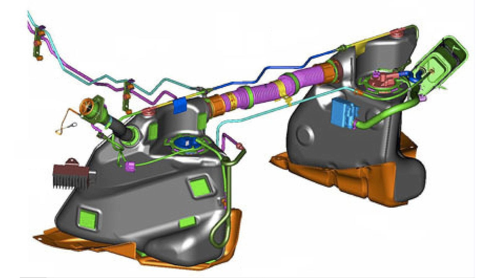
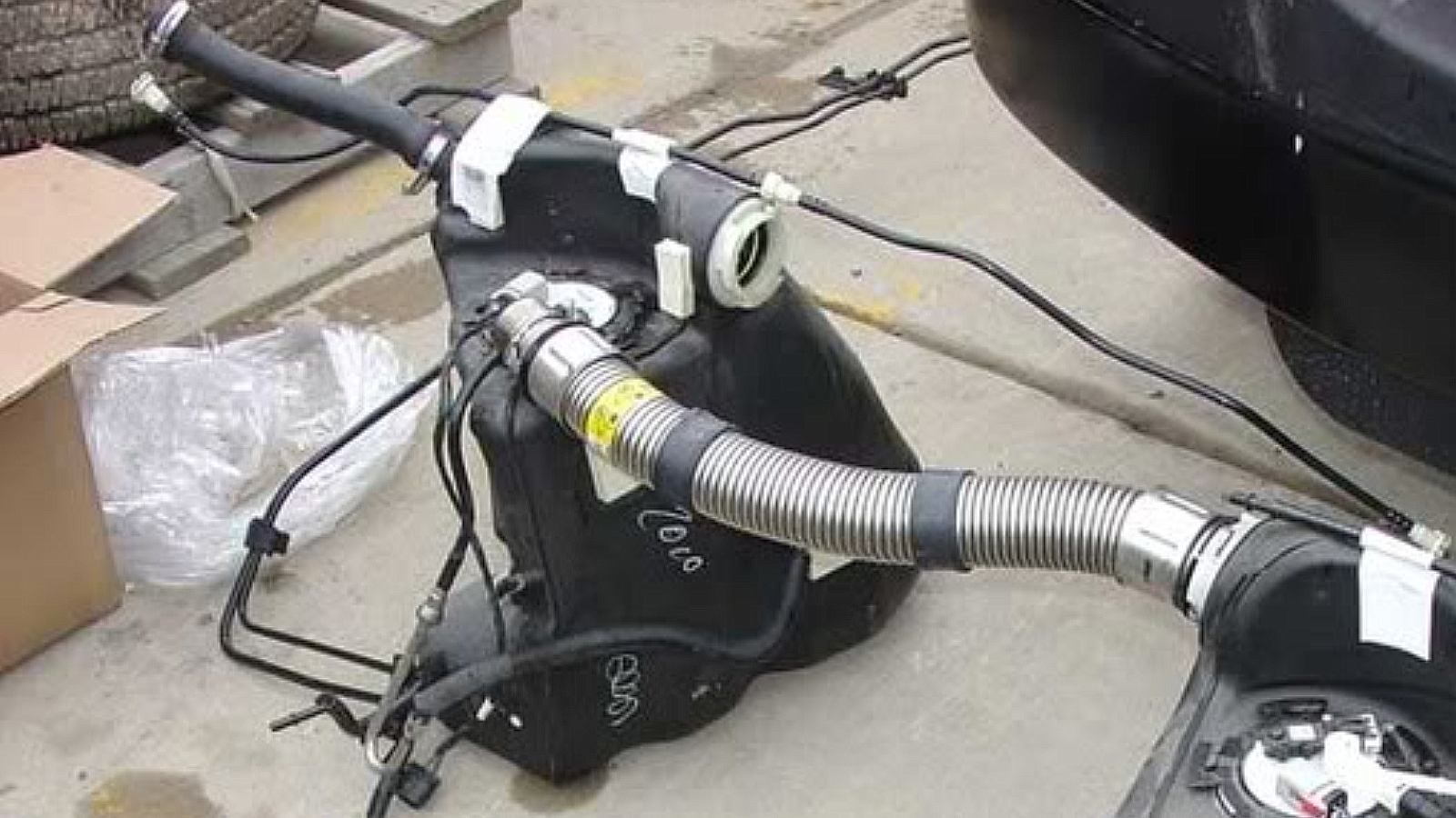
This fuel tank system has two nine-gallon “saddlebag”-type tanks joined by a large crossover hose. The tank on the left (driver) side is where new fuel enters from the fill hose, as well as where the feed line going to the engine comes out. It is called the “primary” tank. The tank on the right (passenger) side is called the “secondary” tank.
The corrugated stainless steel crossover hose contains two lines: a feed pipe going to a siphon pump in the right tank, and a return pipe to ensure the right tank empties before the left tank does.
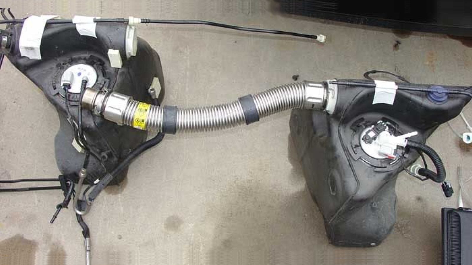
This two-tank setup helps to distribute the weight of the fuel to both sides of the car which, along with the rear-mounted transmission/differential, better balances the weight of the engine. It also gives more storage space behind the seats while allowing the Corvette to ride low for better road hugging.
But with this two fuel tank system came multiple changes. The pressure regulator is no longer mounted to the fuel rail atop the engine. In fact, there are two pressure regulators: a primary pressure regulator located in the left tank with the main fuel pump, and a secondary pressure regulator located in the right tank with a siphon pump.
The fuel pump directs a flow of fuel to the engine, more, in fact, than the engine can consume. However, instead of being diverted into the fuel rail as before, this system diverts excess fuel under pressure into the right tank via the crossover hose. From there, its pressure is used to drive the syphon pump to force fuel from the right tank back through the crossover hose into the left tank. A primary reason for this configuration was because excess fuel that ended up in the fuel rail got heated by its proximity to the engine, thus increasing its evaporative emissions. In addition, this closed, pressurized system ensures that all of the fuel in the right tank gets consumed before the fuel level in the left tank begins to drop — with at which point the fuel gauge reading half-full.
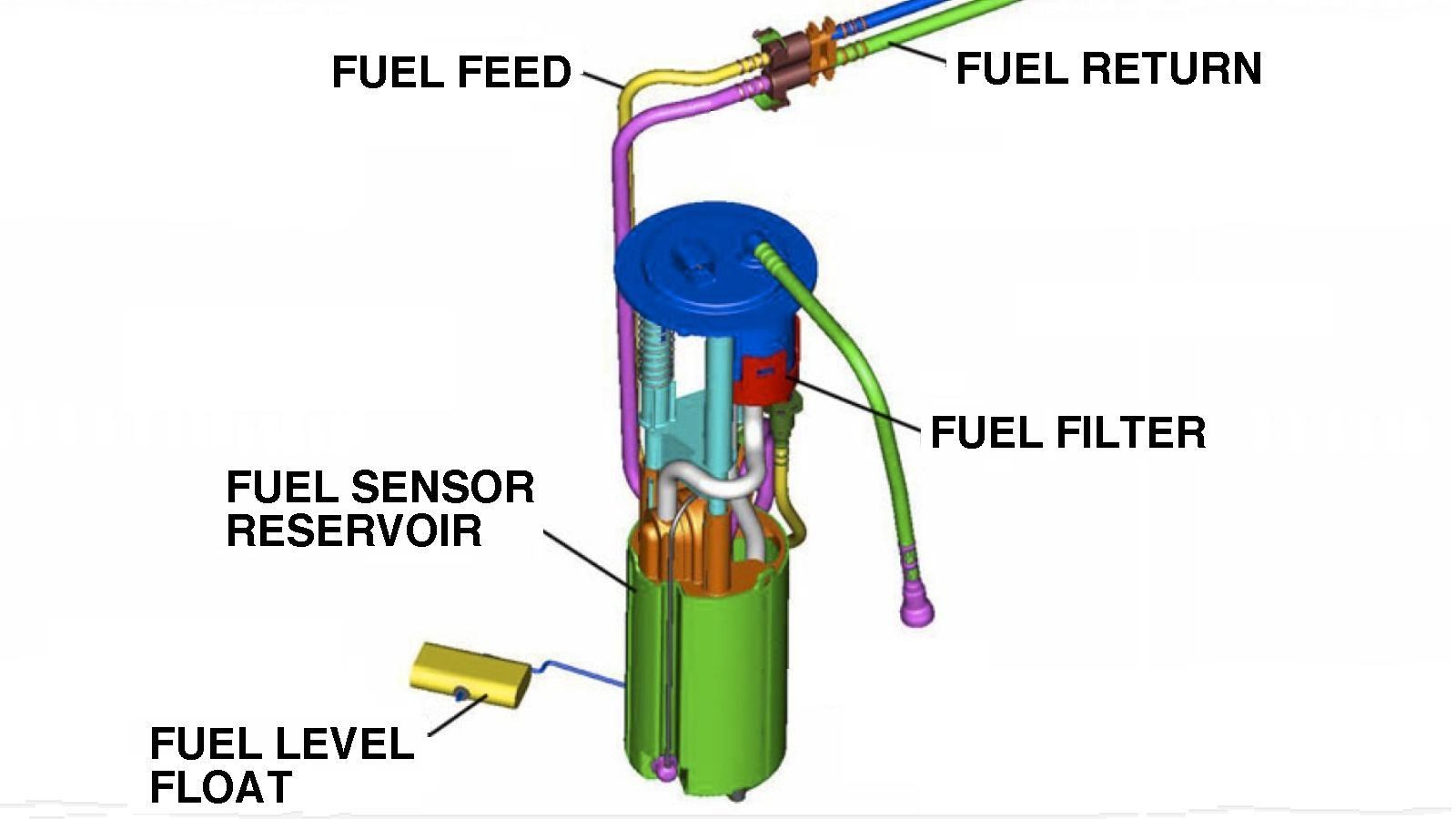
So, where is the fuel filter in all this, you ask?
According to the service manual, the fuel filter is “contained in the fuel sender assembly inside the left fuel tank. The paper filter element of the fuel filter traps particles in the fuel that may damage the fuel injection system. The fuel filter housing is made to withstand maximum fuel system pressure, exposure to fuel additives and changes in temperature. There is no service interval for fuel filter replacement. Other documents indicate that the fuel filter should be good for 100,000 miles.
However, with this new saddlebag fuel tank setup, a number of Corvette owners have run into an issue with the fuel level sensor in the right tank’s fuel sending unit malfunctioning. If the rheostat surface in this sensor tarnishes or the float arm “fingers” contacting it wear down, it sends no voltage data to the Powertrain Control Module (the PCM calculates how much fuel is in the two tanks and displays the combined level on the fuel gauge). An indication that this sensor needs to be replaced is when the fuel gauge stops working, and a DTC of P2066 (fuel sensor “B,” secondary tank, performance issue) is triggered. Problems with this sensor apparently become more prevalent if the secondary tank, which empties first, is run with no fuel in it for long periods of time.
But back to the fuel filter. The best ways to clog a fuel filter are (and have always been):
- Using bad gasoline or old racing fuel
- Consistently driving with very low levels of fuel in the primary tank’s pump
- Running out of gas a few times, which facilitates any bottom contaminants getting into the filter
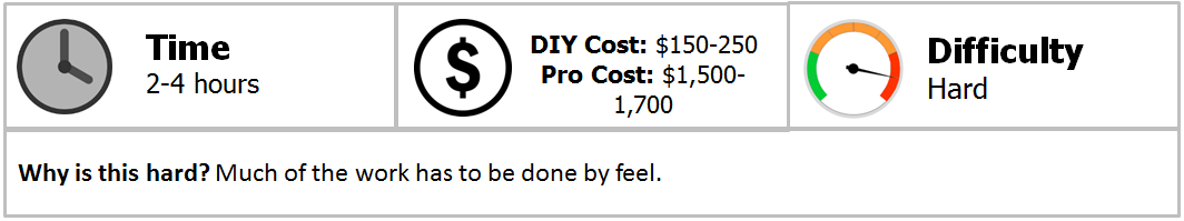
Replacing the fuel filter involves replacing the entire fuel pump. In addition, note that while this can be accomplished without lowering the rear drivetrain on a Corvette with a manual transmission, a vehicle with an automatic transmission will have even less room to work with, which is already so tight much of the work has to be done “blind” — that is, by feel only.
Step 1 – Empty the vehicle of fuel
Before starting, make sure you have less than half a tank — meaning the secondary tank is empty — because both tanks will have to be detached from the undercarriage. If the secondary tank has fuel in it, there’s no way to siphon it out, plus it becomes too heavy to handle.
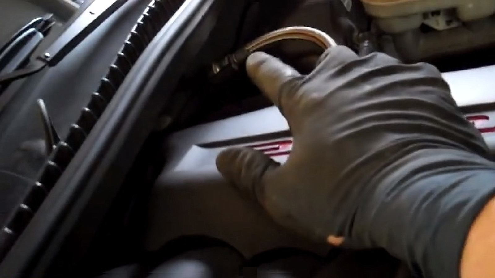
To remove the fuel remaining in the left, primary tank, either siphon it out or use the fuel pump to do the job. To use the fuel pump, first disconnect the fuel line going to the engine from its connection at the bulkhead/firewall on the driver side with a fuel line disconnect tool. Attach one end of a six-foot long, 3/8-inch section of rubber hose over the metal fuel line end, and put the other end into the top of a large, empty gas can placed on the floor.
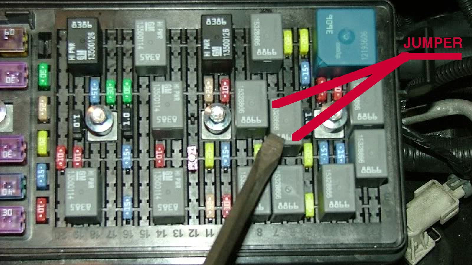
Jumper across two terminals of the fuel pump relay inside the fuse box under the hood on the passenger side. The pump relay shown is #55 in the fuse box, as mapped out on the box’s lid (check to make sure).
Turn ON the ignition (but DON’T start the engine), and let the fuel pump run the primary fuel tank dry.
When the fuel tank is empty, shut the ignition off. Cap and store the gas can in a safe place. Reconnect the car’s fuel line to the fuel rail on the engine. Plug the relay back into the fuse box, and then disconnect the negative terminal of the battery.
Step 2 – Jack the car up, then remove the left rear tire an inner fender liner
Jack up the rear of the car. You will need 20-24 inches of clearance under the rear end to get the tank out, requiring six-ton jack stands or better.
(Related Article: How to Jack Up Your Vette - CorvetteForum.com)
Remove the driver side rear tire and inner fender liner. The liner is held in place by sheet metal screws and plastic push pins. A small access panel showing the top of the primary tank will be revealed.
Step 3 – Disconnect the fuel filler hose, vent return hose and four-pin connector
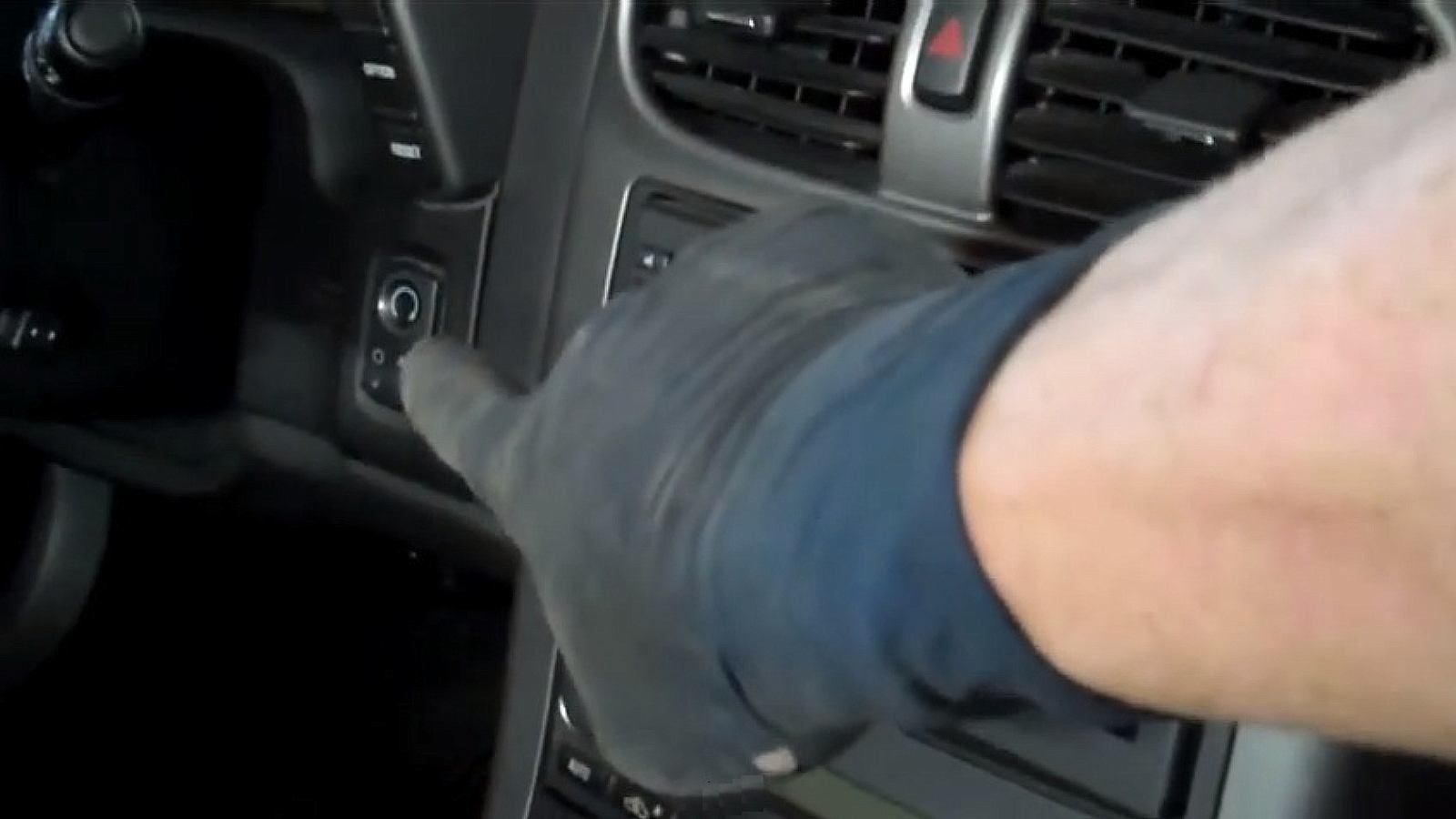
Remove this panel’s cover.
Via this access hole, disconnect the fuel filler hose and the vent return hose at the fuel filler neck. The filler hose coupler is a simple hose clamp, and the vent line has a quick disconnect white, plastic fitting.
Pro Tip
Quick disconnect plastic fittings can disconnect faster if, while pressing the wide spot, one pushes the connection together before pulling it apart.

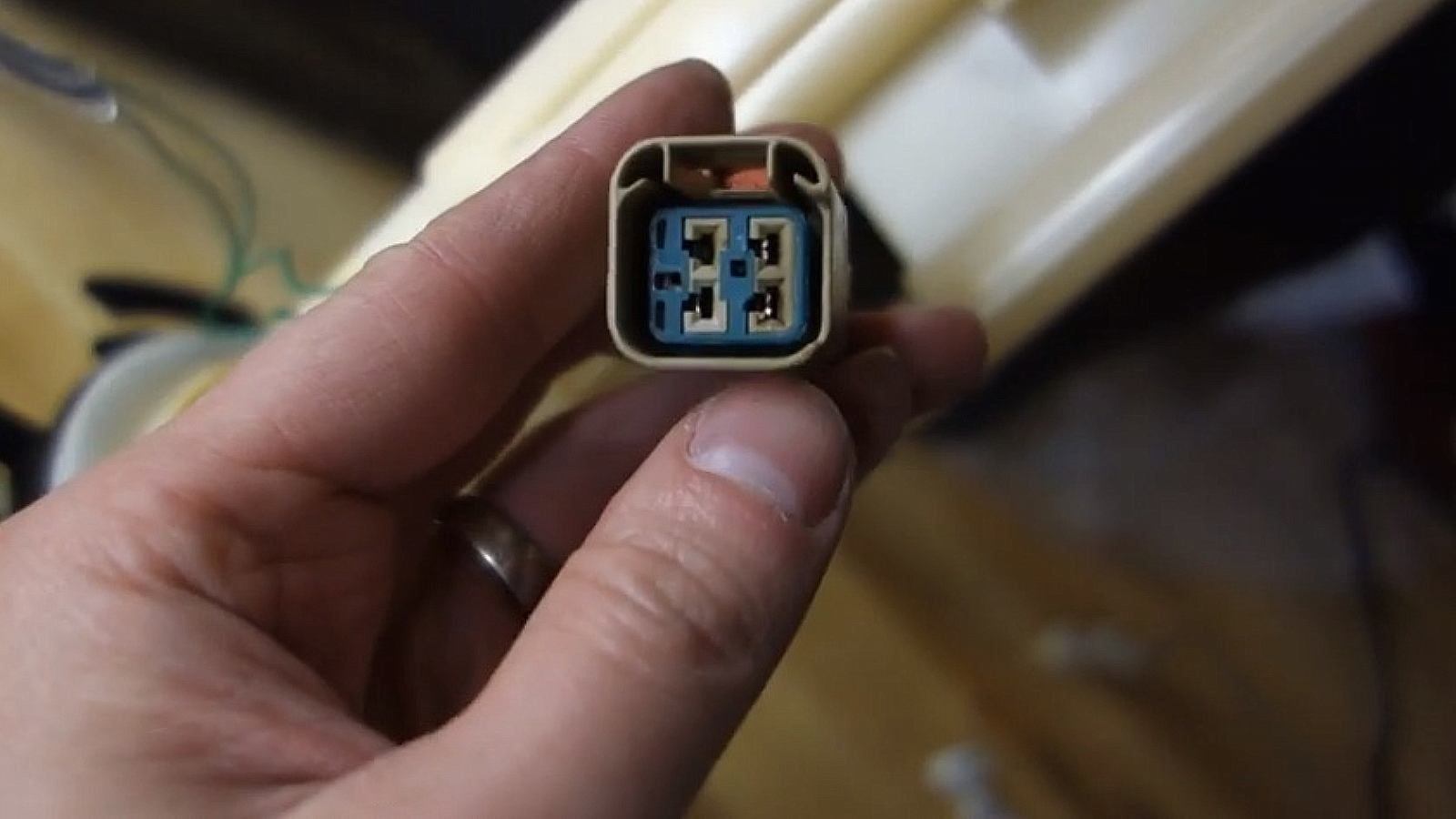
Nearby is a four-pin connector attached to the chassis with a barbed connector plug. The connector holds two thick wires on the outer pins and two thin wires on the inner pins. The thick wires are the positive (red) and ground (black) wires driving the primary tank’s electric fuel pump, and the thin wires connect to the fuel sending sensor. Unplug this connector.

Step 4 – Disconnect the fuel line, EVAP line and vent line
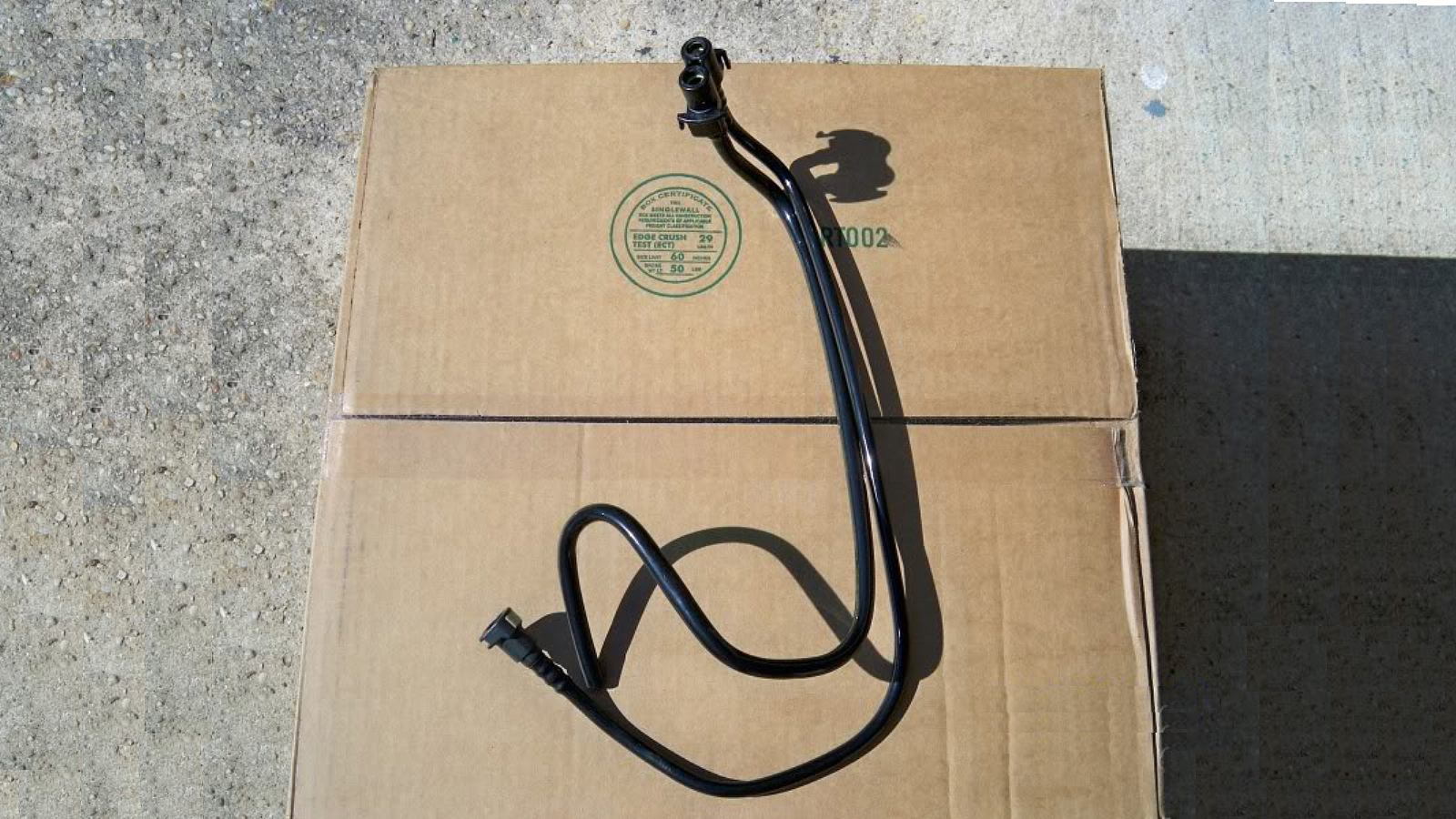
From under the car, disconnect the fuel line that runs to the engine compartment. It’s located behind the tank. It disconnects the same way as the fuel line connection at the bulkhead/firewall. Have a container handy to catch the small amount of fuel trapped in this line. Also, disconnect the EVAP line going from the primary tank across to the secondary tank. There is only one more line to disconnect: a vent line located on top of the tank with the same type of coupler as the vent already removed from the filler neck.

Step 5 – Drop the tanks one inch onto risers
Because both tanks are installed with the crossover connection in place, getting the lateral space needed to pull the crossover connection out of either tank is challenging. A way to accomplish this is, at this point, to remove the aluminum support panels (skid plates) under both tanks. Each is held in place with five bolts. When empty, the tanks are light enough to hang in place via the crossover connection.
You do want the two tanks to descend — but only an inch or so from their top mount positions. Plus, keep in mind that while the crossover tube is somewhat flexible because of its “accordion” structure, you do not want to bend or kink it, as that will make it unusable. To prevent this from happening, riser supports, such as sturdy cardboard boxes, should be placed an inch or so underneath each tank.
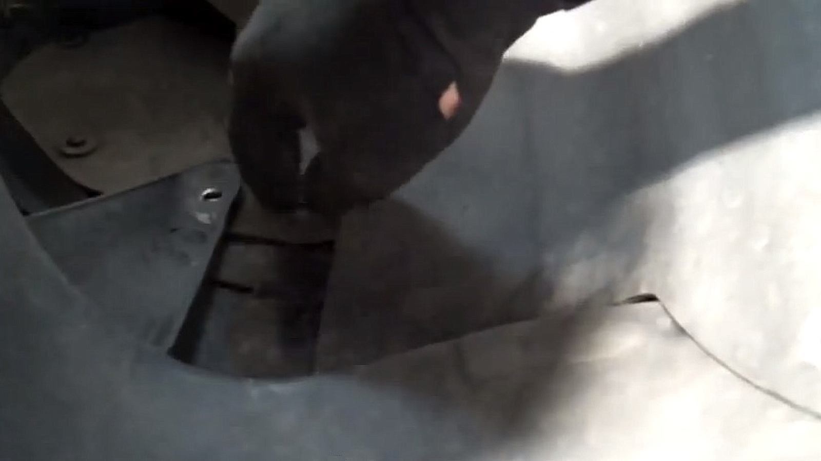
Step 6 – Remove the support fitting
With the risers in place, above the transmission is a spring-loaded “C” shaped support fitting that the accordion crossover tube snaps into. Either unbolt the support bracket from the car body, or pull the crossover tube up, over and out of this fitting.

Alternating between the tanks, pull them both down until each sits on its support riser. This should give you the lateral space you will need to pull the accordion crossover tube coupler out of the primary fuel tank lock fitting.
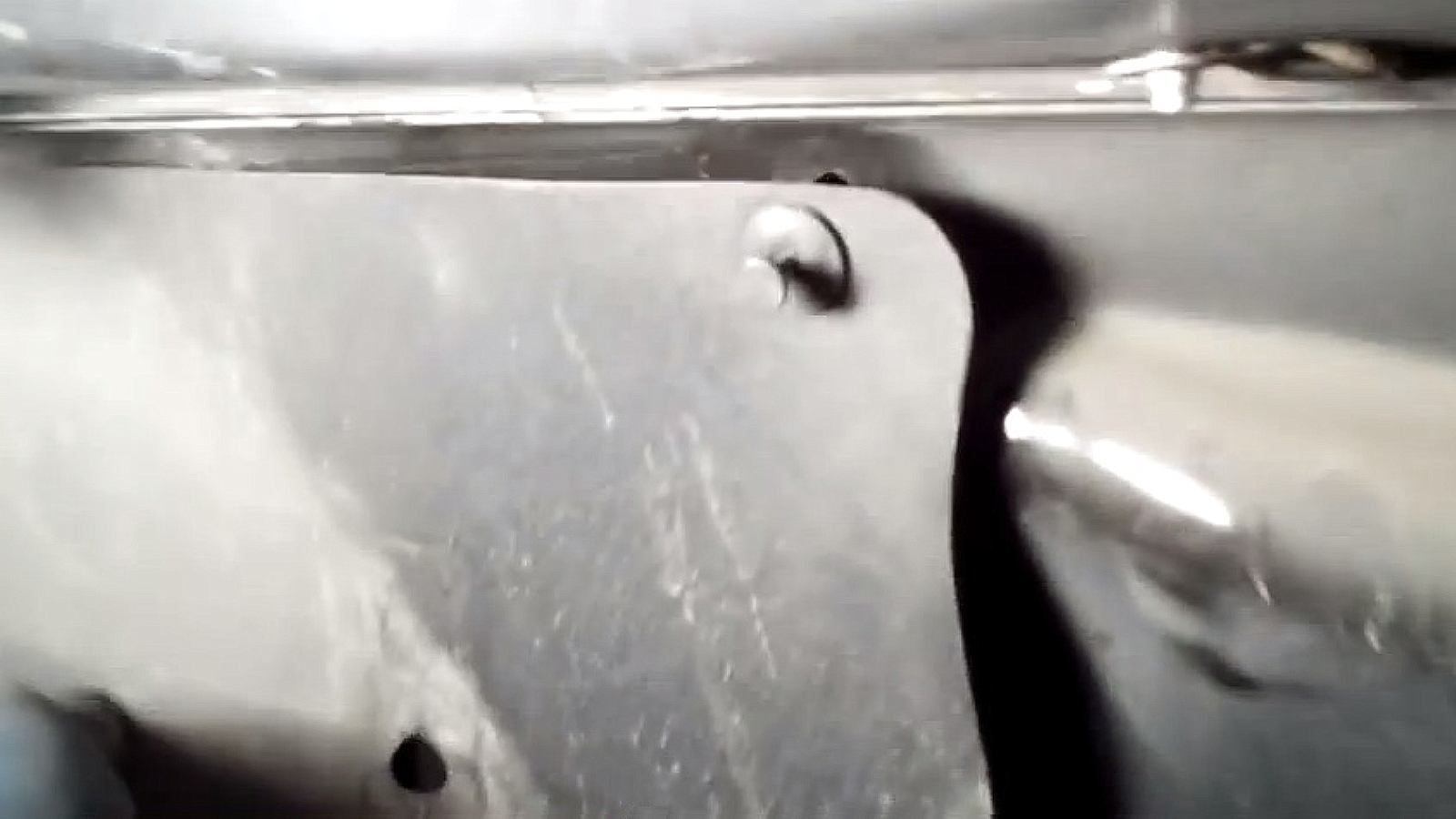
Step 7 – Remove the crossover tube coupler from the primary fuel tank connection
Removing the crossover tube coupler from the primary fuel tank will mostly be done by feel, so carefully study the photos. First up, there is a thin black plastic lock ring that keeps the metal coupler on the end of the crossover tube in place. Pull this black plastic locking ring’s tab out of the notch it’s trapped in, and turn the ring until its tabs (it has three) are free of the notch. Then, turn the metal coupler counterclockwise (only about 20 degrees) to disconnect it from the fitting.

Now comes the really hard part. The crossover tube’s coupler has to be pulled STRAIGHT OUT of the connection on the tank. If it’s twisted or turned, you can break off one or both of the location tabs mounted on the inside top and bottom of the connection. (Note also that in the spirit of full redundancy, there is also a “T” shaped keyway built into the center of this connection to prevent the crossover tube from being connected upside down, which you will see when it’s disconnected.)
A way to get enough leverage to pull the coupler out is by using a very large, adjustable (offset) pliers (Channel-locks), and grabbing the end of the crossover tube by the metal ferrule just before the ferrule widens and the accordion structure begins.

Then, holding some scrap lumber below the connection and up against he primary fuel tank’s right side, you should be able to get enough leverage with the handle of the pliers set against your lumber fulcrum to pry the coupler straight out of the tank connection.
Step 8 – Remove the primary fuel tank and pull the fuel pump out
Tie the now-loose end of the crossover tube up in a horizontal position, then remove the riser and place the primary tank on the floor.
Atop the primary fuel tank is a large locking ring that secures the fuel pump inside the tank. There is a special tool to remove this fitting, but you can also gently rotate it counterclockwise with a plastic mallet and dowel.

Pull the pump halfway out of the tank. With the pump in this position, you can then disconnect the line that goes to the secondary tank via the crossover tube (it has a pinch-connector you can release by squeezing), as well as the line that comes from the secondary tank via the crossover tube, which goes into the white fuel pump bucket with its end resting at the pump’s bottom. This line is held in place by a Nylon hose clamp.

Now loose, these two lines, held together by the fixture that the crossover tube connects into, can be pulled out of the tank through the crossover tube’s nylon connection fitting. The two tabs in this fixture with different widths, one at the top and one at the bottom, are now visible, as well as the “T” key between the two lines. Make sure that this alignment fitting is in the proper position when it’s reinserted into the primary fuel tank.
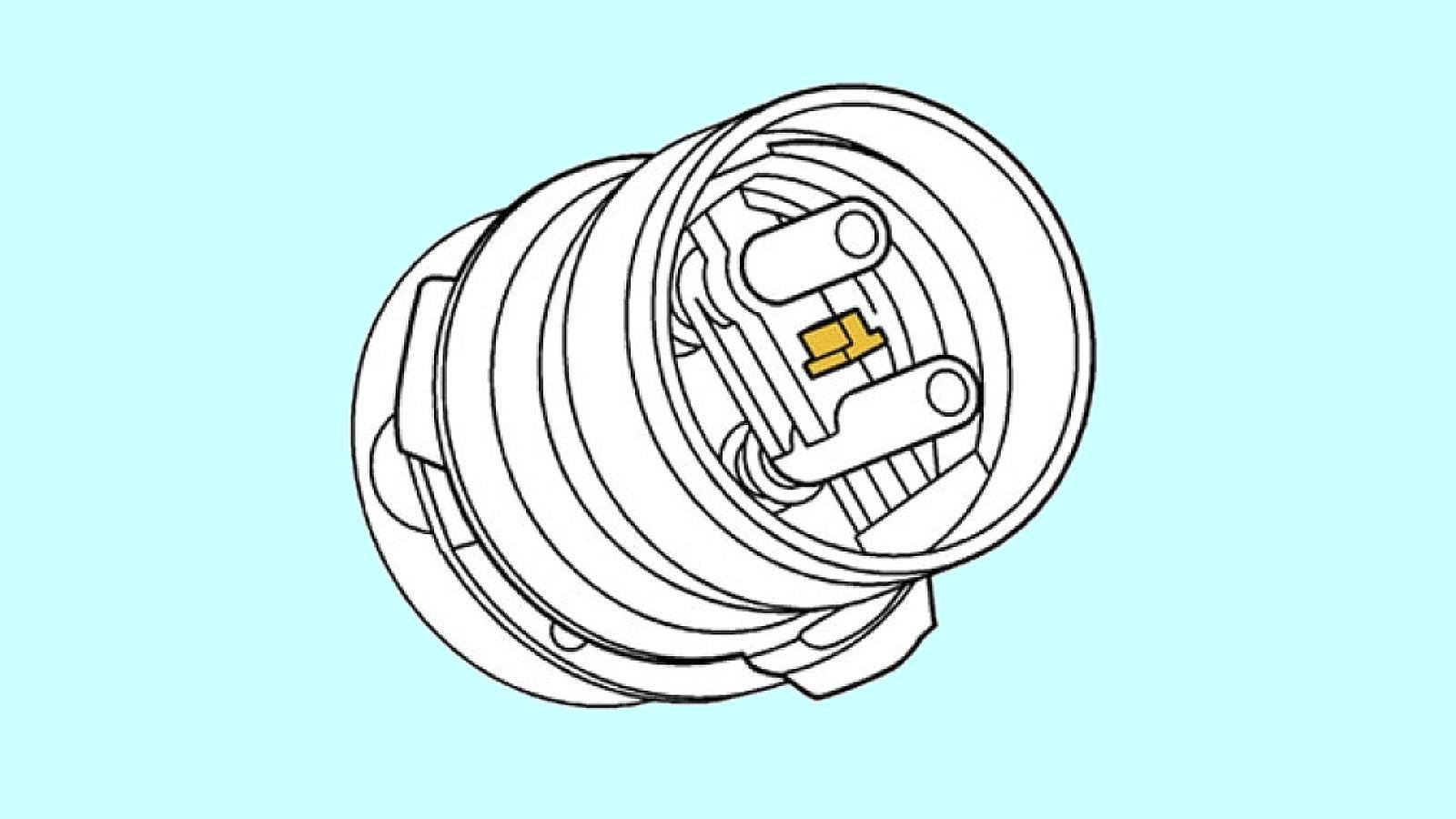
With the two lines removed, slowly fish the pump out of the tank. Care must be taken when maneuvering the long fuel level float wire and float attached to the pump’s fuel level sensor module. Also, be aware that the bottom half of the fuel pump may require some prying with a small screwdriver to clear the opening. Once the pump is clear of the tank, remove the fuel level float wire and float by first unsnapping the front of the fuel level sensor module off then pulling the metal lever out. This will reveal the resistor, or rheostat, card.
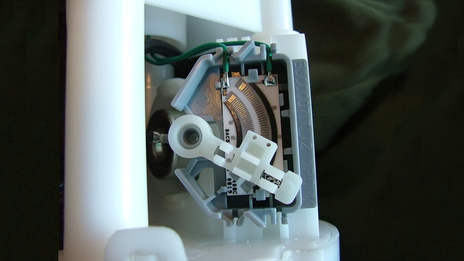
Note that most new fuel pumps don’t come with a fuel level sensor module that controls the sending unit. Thus, you’ll have to transfer the old fuel level sensor over to the new pump. It simply clips off the old pump then onto the new, but unplugging it is fussy.
The two small wires (shown above in green) have to be removed from the old pump’s connector and plugged into the new pump’s connector. Pushing a small pin into a hole on the back of this connector releases the wire connector shell, allowing you to pull it out of the connector housing. From the front, insert a tiny jeweler’s screwdriver into each connection passage to push down a metal tang on the clip, allowing both clip and wire to be pulled out. After you replace the sending unit wires in the new plug, check to make sure the wire plug connections are being held securely in the housing by their tang, then replace the plug in the new pump. Finally, reattach the fuel level float arm back onto the sending unit sensor module, snap on its cover, and replace the sensor in the pump housing.
With the loose crossover lines inserted back in the tank, fish them both out through the top opening and attach a safety string to the end of each.
Step 9 – Replace the fuel pump into the primary fuel tank
Propping the new pump above the tank opening, pull the string up to get the two lines into a position where you can attach the one with the Nylon clip-on fitting in place. Then, feed the return line into the bottom of the fuel pump and secure it with its Nylon fastener. Get the fuel level float arm and float into the tank, making sure there’s no interference with its movement from the two crossover lines. Then, remove the string and lower the fuel pump assembly into the tank. Get the tank opening’s large o-ring back into position, push the pump’s top down, and put the large metal lock ring back on.
Before putting the tank back in the car, take an inventory of the connections and their necessary components. During removal, critical o-rings and o-ring retainers can pop out of these connections, which will cause serious fuel leaks. The connection that goes to the crossover tube has a black o-ring, then a green o-ring held in place with a plastic retainer. The two connections in the middle for the feed and return lines also have an o-ring held in place with a plastic retainer. Note the “T” shaped alignment hole for the crossover connection. Before plugging the lines back together, put a few drops of oil or silicone on all of the o-rings to help prevent them from being pinched or torn during reassembly. Also, put some oil or silicone on the fittings in the crossover tube connector.

Step 10 – Replace the fuel tank
Reposition the tank under the car with the filler neck pointed where it goes, and feed the wiring harness over to the access panel location. Lift the tank up close to the proper height, and slide the riser box back underneath it to keep it in place. Reattach the fuel line going from the tank to the hard line leading to the engine compartment with a fuel line disconnect tool. Reach above the tank to reconnect the vent line you can’t see. Reattach the EVAP line going from the primary tank to the secondary tank. Then, hoist the tank into its final position and, using the five bolts, reattach the aluminum skid plate under the primary fuel tank.
Step 11 – Reconnect the crossover tube
Bring the crossover tube connection over to the primary tank, and see if you can reconnect the crossover tube coupler to the primary tank fitting. If you need more leverage for this operation, use your large offset pliers (Channellock) again, but this time with scrap lumber set against the side of the transmission/differential. Hold the jaws gently around the corrugated end of the ferrule (don’t squeeze!) and, with the jaws pressed firmly up against the flared end of the ferrule plus the handle leveraged against the lumber fulcrum, pry the coupler back into its seated position. When it’s all the way in, turning the coupler clockwise will engage the tank’s connection. Finish the connection with a short turn, then rotate the black plastic ring until the tab falls into the notch, locking the coupler.

Step 12 – Reassemble the fuel system
- Hoist the secondary tank into its final position, remove the riser, and reattach the aluminum skid plate underneath it using the five bolts.
- From the access panel, reattach the fuel filler neck and vent tube, as well as the fuel pump harness to the chassis connector.
- Put the fuel you took out of the tank back into the car. Reconnect the battery, and make sure the fuel pump relay was plugged back into the fuse block.
- Turn on the ignition but don’t start the engine. Note that the fuel pump will run a few seconds to prime the line then shut off. This is normal. After the car is started, the fuel pump will run full time.
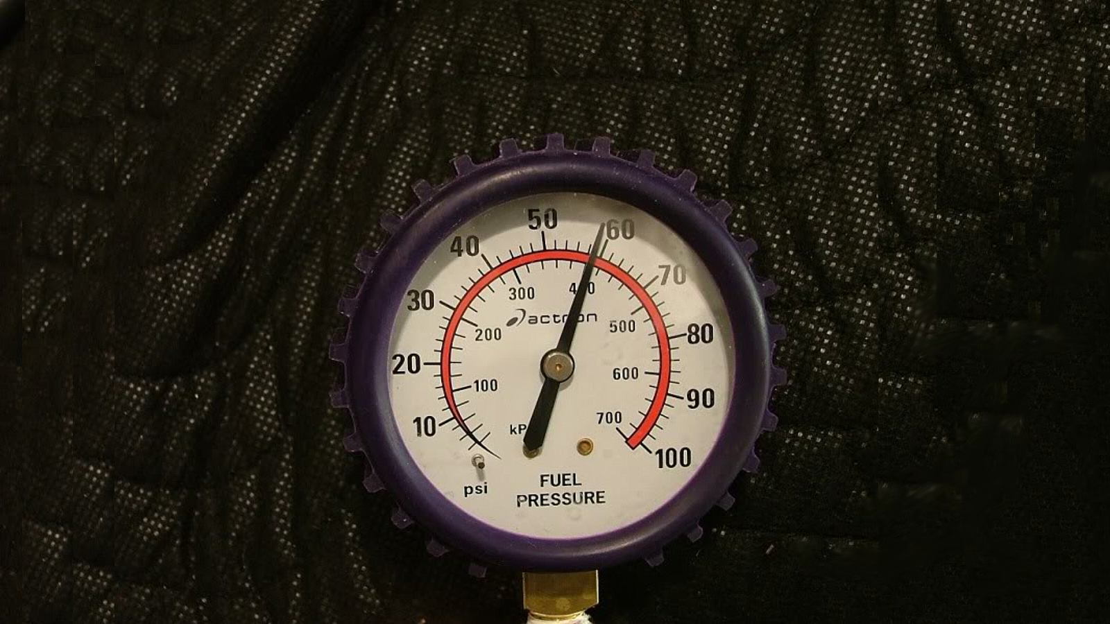
If everything went according to plan, you should have close to 60 psi at the fuel rail connector.
Finally, re-install the access cover, rear tire fender liner and rear wheel.
Related Discussions and Videos
- Fuel Pump Replacement - CorvetteForum.com
- Removing the Secondary Tank Sending Unit - YouTube.com
- Additional Video About the Sending Unit - YouTube.com
- Discussion About Removing the Crossover Tube - CorvetteForum.com
- Fuel Filter Servicing? - CorvetteForum.com
- PDF of Fuel Tank System Diagrams - Hessh.de