C6 Corvette: How to Install a Dual Mode Exhaust Switch
If your Corvette is equipped with the (RPO) NPP exhaust, you know how cool it is to have this dual-mode exhaust feature. It's quiet at times, while throaty and powerful at start-up and acceleration. Wouldn't it be even cooler if you could control it with a switch or button? Learn how to install one here.
This article applies to the C6 Corvette (2005-2013).
The NPP exhaust was designed to improve sound and performance, while still meet emission guidelines. In this dual-mode or bi-mode system, there are two different outlets coming from the mufflers. There is a butterfly valve or flap in the straight through pipe of each muffler. When closed, exhaust is forced through the entire muffler circuit and quieted. When open, the exhaust runs straight through, beefing up the sound and performance.
This dual-mode is controlled by engine vacuum pressure. The valves will be open upon start-up (as they remain open when the car is off, which helps to prevents the flaps from “sticking” when stored) until the vacuum pressure builds (2-3 seconds) and they close. Under normal driving conditions, the flaps remain closed, and the exhaust will pass through the baffle chamber of the muffler. The butterfly operation is controlled by the throttle body sensor and will then open on certain acceleration, depending on RPM and percent of throttle. This throttle body sensor may determine driver intent, but now you can have driver control!

Materials Needed
- Switch kit
OR
- Mini add-a-circuit
- 2 position switch/button
- #16 gauge automotive wire
- Electrical connectors (male and female)
- Electric tape or wire shrink wrap
- Wire cutter, stripper and crimp tool
- Velcro or drill
A simple solution (that is, if you want the open, throaty sound at the tips) would be to simply pull the 10A fuse to the dual-mode exhaust. Of course, you’ll completely lose the “quiet-side” of this bi-mode system. There may be times that you welcome the “muffled” purr, like early morning departures, late night arrivals, or the occasional important phone conversation to name a few. Plus, how cool would it be to impress your passengers with a flip of a secret switch or press of a button.
There are aftermarket “all-included” kits for such an install, as well as a complete DIY (gather components) method. This article is not intended to endorse either option, but instead to give you a step-by-step guide to the complete process.
Step 1 – Pull back carpet and remove floor board/panel
Pull back the carpet on the passenger side foot well. Remove the floor board/panel to access the fuse block.
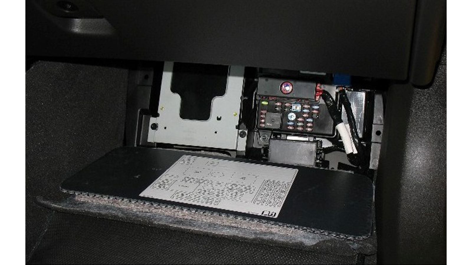
Step 2 – Remove the 10A exhaust fuse
Using the fuse puller, remove the 10A exhaust fuse.
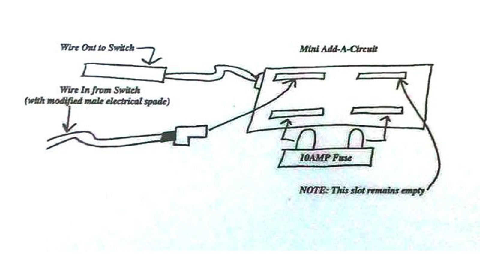
Step 3 – Wire/install a mini add-a-circuit
Strip #16 gauge wire and add a male spade clip by crimping (or solder if you prefer). You may need to cut the spade clip to fit in the circuit slot. Insert the spade clip into the add-a-circuit to extend the wiring to the switch location. Use the appropriate length of wire necessary to place the switch where desired. You will also need the same length of wire spliced to the existing wire of the add-a-circuit.

Shrink wrap or tape these connections as desired. Install the original 10A fuse in the add-a-circuit and install the add-a-circuit to the exhaust fuse location in the fuse block.
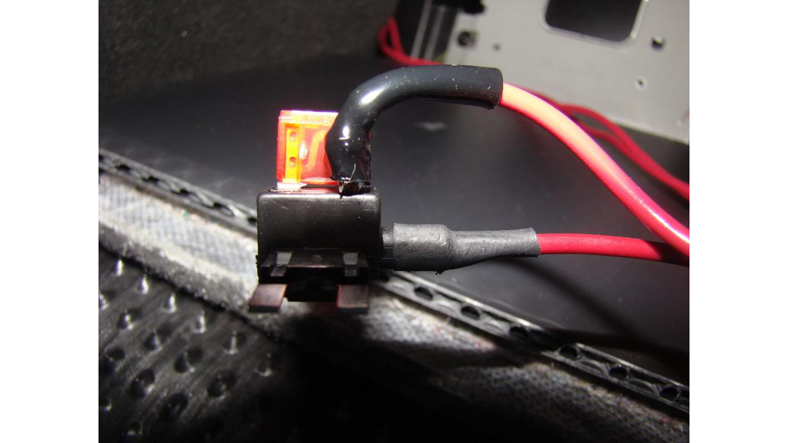
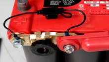
Figure 4. Completed integration of add-a-circuit wiring. 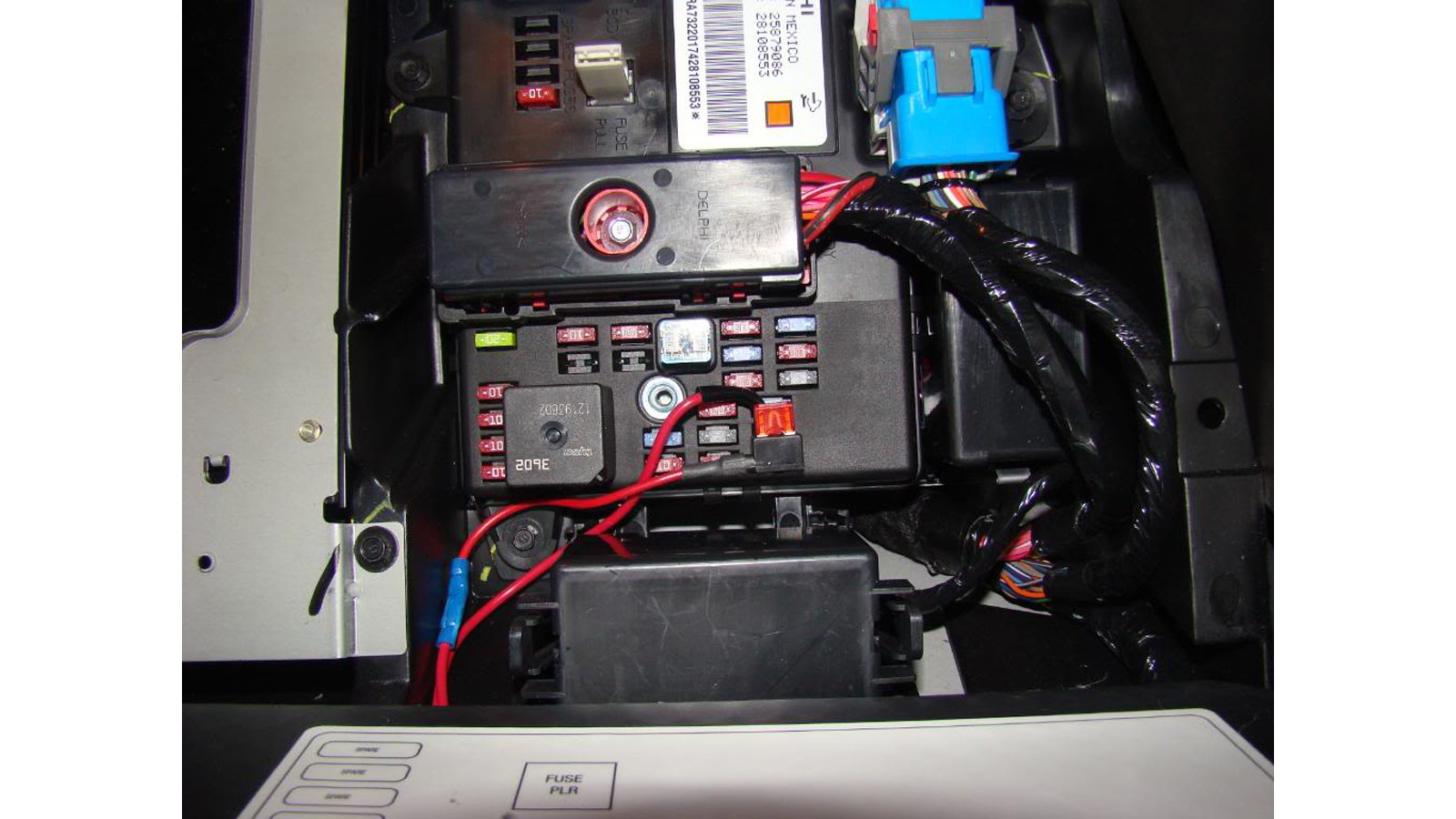
Figure 5. Installation to fuse block.
Pro Tip
If you have purchased a kit, Step 3 will not be necessary as the revised wiring harness will be included. Simply install the 10A fuse into given add-a-circuit harness and plug the harness into the fuse block location. Also, if the kit includes a wireless FOB for activation, the receiving unit will need to be grounded.
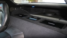
Step 4 – Run (nest and hide) the wires to the desired location for the switch
There are many places to install the switch. Some have installed it in the glove box, under the dash, at an unused switch location, and even on the dead pedal on the floor. You may need to drill a hole for the switch if desired. Using Velcro is also an option.
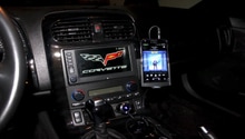
Step 5 – Secure the switch and attach the wires to the switch terminals
It does not matter which wire goes to which switch post terminal in order to function. It may, though, if your switch has a light or LED and you prefer “light on” or “light off” to designate “open” or original functionality.

Pro Tip
If you have purchased a kit with a wireless FOB, then Step 5 is unnecessary. Simply hide the receiving unit under the dash or in the glove box. You may then attach the FOB to a location using Velcro or prefer to keep it free.
Step 6 – Replace the fuse block cover/floor panel and carpet
Replace the fuse block cover as well as the floor panel and carpet. Now, when you want to “open” the exhaust flaps and bypass the sound dampening, simply flip the switch and the circuit will be broken, just as if you had pulled the fuse. Flip it back, and the circuit is once again complete, and you can return to the normal operation as originally designed. Enjoy!
Related Discussions
- DIY Dual Mode Exhaust - CorvetteForum.com
- Write-up DIY Dual Mode Exhaust - CorvetteForum.com
- Mild2Wild Switch Kit - CorvetteForum.com