Dual air meter FI unit
 04-01-2014, 01:56 AM
#1
Race Director


Thread Starter
Member Since: Mar 2001
Location: Mustang OK
Posts: 13,852
Received 3,772 Likes
on
1,674 Posts
2023 C1 of the Year Finalist - Modified
2015 C1 of the Year Finalist

For those who may be interested in this sort of thing, here is one that I'm finishing up with.
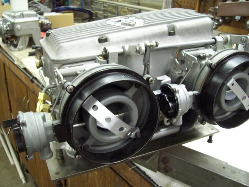
The fuel meter side is virtually unchanged (but ONLY EXternally).
The fuel meter side is virtually unchanged (but ONLY EXternally).


 04-01-2014, 06:07 AM
#4
Safety Car

Wow Tom, looks like a tremendous job. Looking forward to more info as you progress.
How did you block off the center stock port on the plenum? It almost looks like it's undetectable in the pictures.
Rich
How did you block off the center stock port on the plenum? It almost looks like it's undetectable in the pictures.
Rich
 04-01-2014, 10:08 AM
#7
Race Director
Thread Starter
Member Since: Mar 2001
Location: Mustang OK
Posts: 13,852
Received 3,772 Likes
on
1,674 Posts
2023 C1 of the Year Finalist - Modified
2015 C1 of the Year Finalist
It was sent to me by one of the CF members right here.
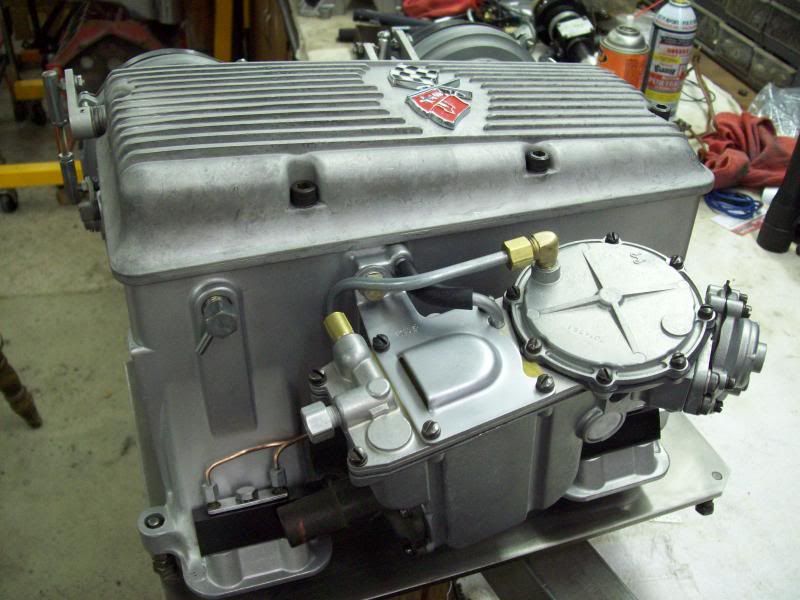
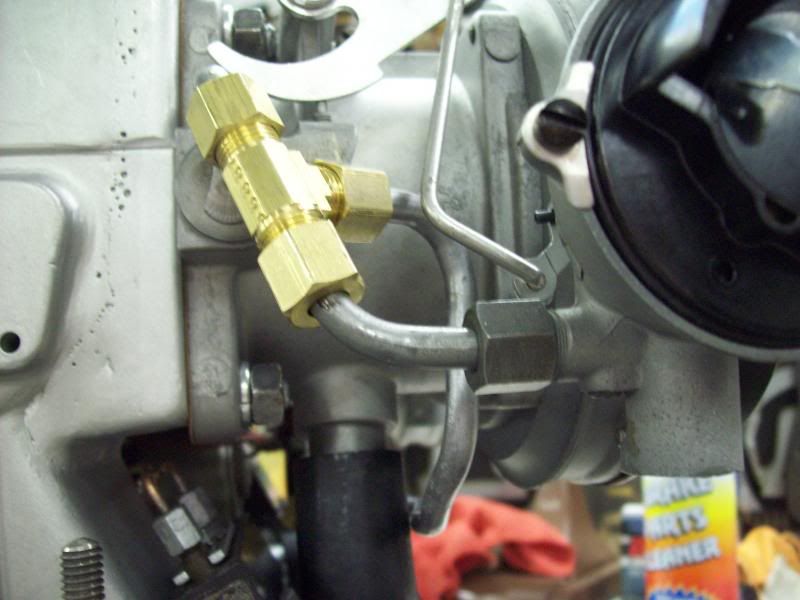
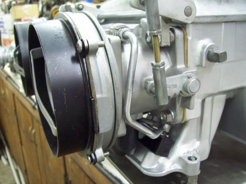
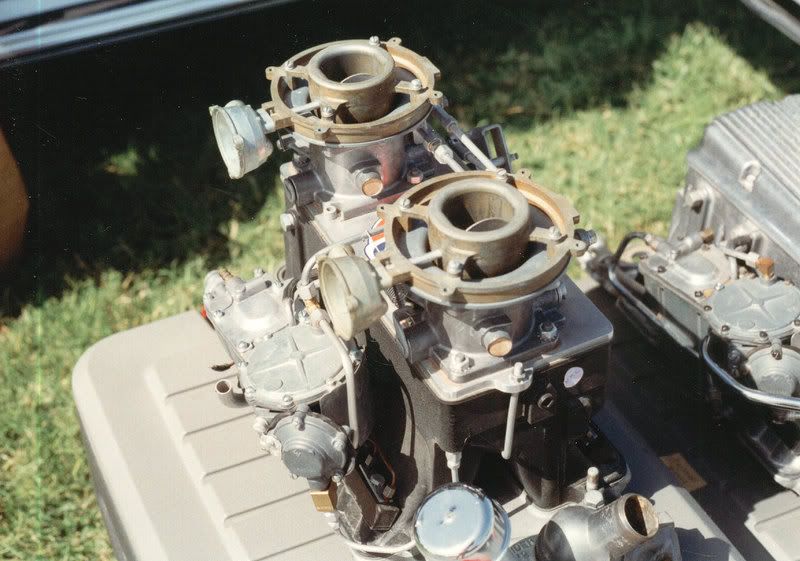
It had NO starting circuit nor chokes. I fabricated everything for a starting circuit system just like on a 7380 unit (micro switch, 7380 fuel spider/solenoid and the fuel meter lid had to be changed). I fabricated all new main signal lines and rounded up everything to make the chokes work and fabricated vacuum lines for the choke pull off. The car will have headers, thus an exhaust heated choke tube cannot be used, so I installed elec choke covers---------------which work perfect!
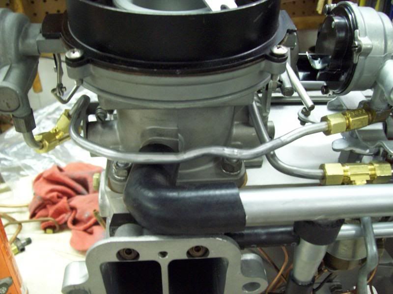
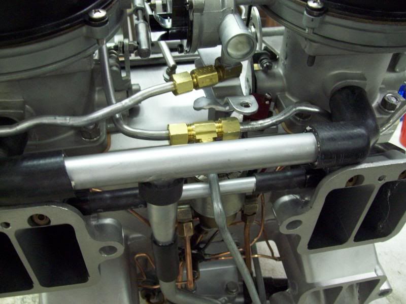
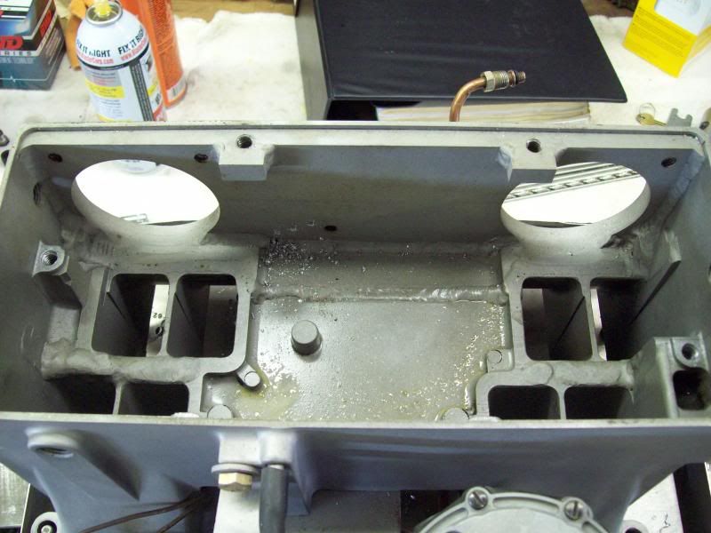
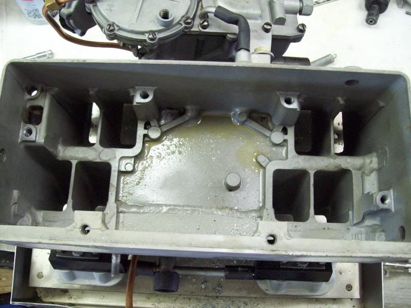
The entire left side of the plenum was cut out, the runners were cut down to the floor of the plenum, a 1/2in alum plate welded in, machined, holes were cut in place and new studs installed.
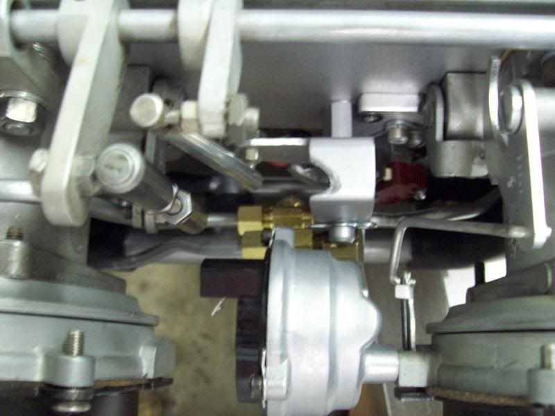
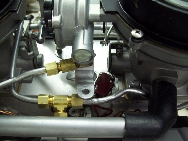
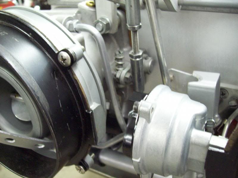
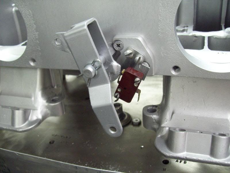
Since there was no starting circuit, I had to fabricate a method of mounting a micro switch from scratch. So here is where I put it. With everything assembled, it's almost completely hidden.
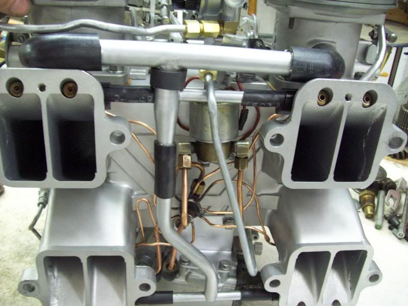
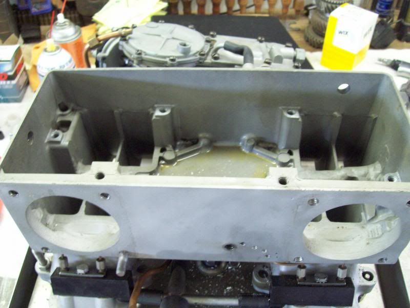
This is the way the unit came to me. No chokes (the choke housing on the front AM is empty) and no micro switch.

It had NO starting circuit nor chokes. I fabricated everything for a starting circuit system just like on a 7380 unit (micro switch, 7380 fuel spider/solenoid and the fuel meter lid had to be changed). I fabricated all new main signal lines and rounded up everything to make the chokes work and fabricated vacuum lines for the choke pull off. The car will have headers, thus an exhaust heated choke tube cannot be used, so I installed elec choke covers---------------which work perfect!
The entire left side of the plenum was cut out, the runners were cut down to the floor of the plenum, a 1/2in alum plate welded in, machined, holes were cut in place and new studs installed.
Since there was no starting circuit, I had to fabricate a method of mounting a micro switch from scratch. So here is where I put it. With everything assembled, it's almost completely hidden.
This is the way the unit came to me. No chokes (the choke housing on the front AM is empty) and no micro switch.
Last edited by DZAUTO; 04-01-2014 at 10:24 AM.
04-01-2014, 10:44 AM
#8
Race Director
Thread Starter
Member Since: Mar 2001
Location: Mustang OK
Posts: 13,852
Received 3,772 Likes
on
1,674 Posts
2023 C1 of the Year Finalist - Modified
2015 C1 of the Year Finalist
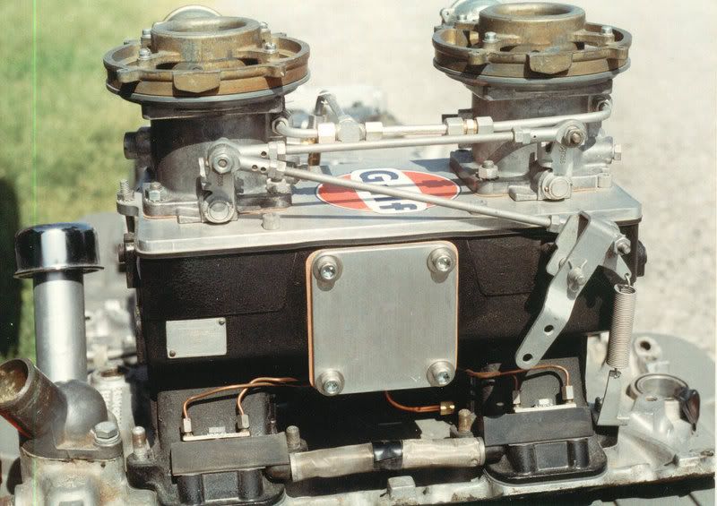
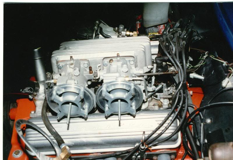
This is the more common method of building a dual air meter unit. This particular one was on the Grady Davis Gulf Oil racer.
And this is an early style which is on the SR2 that was recently sold by Rich Mason. This is the type that I want to build for the 56
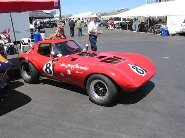
This is one installed on one of Bill Thomas' Cheetahs.
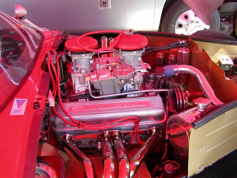
And this is an early style which is on the SR2 that was recently sold by Rich Mason. This is the type that I want to build for the 56
This is one installed on one of Bill Thomas' Cheetahs.
 04-01-2014, 05:29 PM
#10


Tom
did you modify the spill plunger/spill valve to compensate for the 1/2 strength main signal, or was that already done?
I know a bushing was installed in the "tack" type spill valve to decrease the id, and the head of the tack was reduced proportionally. Any photos AND dimensions would be appreciated. Bill Thomas supposedly did some special maching to the tips of the nozzles, but was secretive about details because he wanted to MARKET a dual a/m setup. What are the intake runner lengths (plenum floor to valve) on this unit versus a production plenum? As a FI guy (I run a 1963 unit on my 1956) I always enjoy your posts.Keep up the good work, and keep us updated. thanks.
04-01-2014, 05:44 PM
#11
Race Director
Thread Starter
Member Since: Mar 2001
Location: Mustang OK
Posts: 13,852
Received 3,772 Likes
on
1,674 Posts
2023 C1 of the Year Finalist - Modified
2015 C1 of the Year Finalist
The "thumb tack" style spill valve had already been modified as you mentioned. The Nozzles had been modified and the spring in the enrichment housing had about one coil cut off. All of the above were modifications per Bill Thomas' specs.
Originally, I was tasked to install a starting circuit. One thing led to another, and I did a total rebuild in addition to the other things.
I'm especially pleased with the way the chokes turned out.
Originally, I was tasked to install a starting circuit. One thing led to another, and I did a total rebuild in addition to the other things.
I'm especially pleased with the way the chokes turned out.
04-02-2014, 08:50 AM
#13
Race Director
Thread Starter
Member Since: Mar 2001
Location: Mustang OK
Posts: 13,852
Received 3,772 Likes
on
1,674 Posts
2023 C1 of the Year Finalist - Modified
2015 C1 of the Year Finalist
It's not my unit. It belongs to one of the CF members here. As I understand, he has a 63 race car that it will go on. We'll have to wait until he gets it installed to see how it does.
04-02-2014, 09:55 AM
#14
Melting Slicks


Hats off to you guys with the skills to make these things happen. My skill level is pretty much limited to changing parts out, and I have great admiration for the experts.
04-02-2014, 10:58 AM
#15
Melting Slicks

Member Since: Feb 2011
Location: Middletown Ohio
Posts: 2,892
Received 167 Likes
on
130 Posts
2016 C1 of Year Finalist
Tom,
A guy in Columbus , Ohio had a C1 dual air horn unit on Craigslist a few years ago.
Very cool.
I just couldn't afford it at the time.
Bruce B
A guy in Columbus , Ohio had a C1 dual air horn unit on Craigslist a few years ago.
Very cool.
I just couldn't afford it at the time.
Bruce B
04-02-2014, 03:10 PM
#16
Drifting

The "thumb tack" style spill valve had already been modified as you mentioned. The Nozzles had been modified and the spring in the enrichment housing had about one coil cut off. All of the above were modifications per Bill Thomas' specs.
Originally, I was tasked to install a starting circuit. One thing led to another, and I did a total rebuild in addition to the other things.
I'm especially pleased with the way the chokes turned out.
Originally, I was tasked to install a starting circuit. One thing led to another, and I did a total rebuild in addition to the other things.
I'm especially pleased with the way the chokes turned out.
Very interesting looks killer!
rustylugnuts
 04-02-2014, 03:22 PM
#17
Team Owner


Member Since: Mar 2003
Location: Greenville, Indiana
Posts: 26,118
Received 1,843 Likes
on
1,398 Posts

 ) but it looks like they come up a little short. Don't know whether this Gulf Oil dyno sheet is for a 327 or a 377 engine. It says 327. I have always heard, they don't run worth a crap over the whole rpm band!
http://www.racingicons.com/gs/004/gulf.htm
Last edited by MikeM; 04-02-2014 at 03:33 PM.
04-02-2014, 05:18 PM
#18
Race Director
Member Since: Jun 2006
Location: Inverness FL
Posts: 17,891
Received 727 Likes
on
621 Posts
St. Jude Donor '07
Hold yer fire. I'm merely the messenger() but it looks like they come up a little short. Don't know whether this Gulf Oil dyno sheet is for a 327 or a 377 engine. It says 327. I have always heard, they don't run worth a crap over the whole rpm band!
http://www.racingicons.com/gs/004/gulf.htm
) but it looks like they come up a little short. Don't know whether this Gulf Oil dyno sheet is for a 327 or a 377 engine. It says 327. I have always heard, they don't run worth a crap over the whole rpm band!http://www.racingicons.com/gs/004/gulf.htm
 ) your chart seems to support that theory...
Bill
04-02-2014, 05:40 PM
#19
Burning Brakes

The "thumb tack" style spill valve had already been modified as you mentioned. The Nozzles had been modified and the spring in the enrichment housing had about one coil cut off. All of the above were modifications per Bill Thomas' specs.
Originally, I was tasked to install a starting circuit. One thing led to another, and I did a total rebuild in addition to the other things.
I'm especially pleased with the way the chokes turned out.
Originally, I was tasked to install a starting circuit. One thing led to another, and I did a total rebuild in addition to the other things.
I'm especially pleased with the way the chokes turned out.
04-02-2014, 05:43 PM
#20
Burning Brakes
It was sent to me by one of the CF members right here.
It had NO starting circuit nor chokes. I fabricated everything for a starting circuit system just like on a 7380 unit (micro switch, 7380 fuel spider/solenoid and the fuel meter lid had to be changed). I fabricated all new main signal lines and rounded up everything to make the chokes work and fabricated vacuum lines for the choke pull off. The car will have headers, thus an exhaust heated choke tube cannot be used, so I installed elec choke covers---------------which work perfect!
The entire left side of the plenum was cut out, the runners were cut down to the floor of the plenum, a 1/2in alum plate welded in, machined, holes were cut in place and new studs installed.
Since there was no starting circuit, I had to fabricate a method of mounting a micro switch from scratch. So here is where I put it. With everything assembled, it's almost completely hidden.
This is the way the unit came to me. No chokes (the choke housing on the front AM is empty) and no micro switch.