When you click on links to various merchants on this site and make a purchase, this can result in this site earning a commission. Affiliate programs and affiliations include, but are not limited to, the eBay Partner Network.
Will the diff yoke and u-joint interfere with the tunnel in the floorpan? It's very tight in there.
Not sure. I did not really raise the front of the differential much. It was a combination of raising the front and lowering the rear that got me to the correct angle. But if needed, I am prepared to modify the tunnel. It was already damaged once from what I assume was a broken universal joint at the rear and the patch that was used needs to be removed and redone. There is actually a piece of aluminum riveted in place under the mess pictured below. It is very visible when looking underneath the car. I plan on having the body on and off the chassis several times after the chassis is completed. I am also concerned with firewall / engine clearance.
Well I have finally gotten to start on the drive shaft tunnel.
I started with a piece of steel tubing that was 3 1/2" in diameter and has a 1/8" wall thickness. I cut that in half with the plasma cutter and then welded support straps and flanges to each half.
I used 1/8" by 7/8" cold rolled steel bar stock to make the support straps for both halves and the same bar stock to make the bolt flange on what will be the top half. I used 3/4" square steel tubing to make the bolt flange for what would end up being the bottom half. After I drilled the through holes in the square tubing I welded small round tubes in the holes. I did this so that when the bolt goes through, and is tightened, it does not crush the square tubing. The holes are sized for eight 5/16" x 18 bolts. The square tubing will also serve as a foundation for mounting to the frame.
Below you can see a little fixture that I made by welding different pieces of steel to my welding table. This is when having a decent welding table with a decent thickness top can be handy. Mine is 1/4" thick. Some are thicker, a lot are thinner. A decent thickness table top lets you weld to the table for jigs, fixtures, hold downs etc. You can later grind the welds, knock the pieces off, and grind everything smooth.
The three pieces of steel at the bottom are welded to the table top. Above that you can see the "U" shaped piece of 1/8 x 7/8" bar that was heated red hot and formed around the fixture.
Here I am welding on the flanges.
Here I have the bottom half in position. Next I need to figure out how this is going to attach the the two cross members.
Bolts will come through the bottom half and thread into the top half to hold it in place.
The rear of the drive shaft tunnel is going to be mounted to the same cross member as the snubber bracket of the differential. This is the easiest end of the tunnel to mount because the tunnel is right over that cross member. The front end of the tunnel, the end closest to the transmission will be a little more difficult because that cross member is further away from the tunnel.
The rear mounting is pretty easy to explain but a little harder to actually do. For the most part I needed to make two off set brackets. One for each side. The easy part is making the first bracket. Heating and bending a piece of 3/16" x 2" cold rolled steel. The hard part was making a second one that was at least near the same as the first. I actually surprised myself with how close I got.
I ground down the sides of a 7/6-14 nut to 5/8" square on the outside. This then fit into the end of the 3/4" square tubing I was using. This served as the mounting point at the rear of the tunnel.
I rounded and shaped my two brackets so that they were not just square pieces of steel. I cut the basic shape with the plasma cutter and used the grinder and sander to clean it up.
I welded the brackets to the back of the rear cross member. I had to notch the differential snubber bracket to get my two new brackets in the correct location. But this is good because it ties those brackets together and makes them all stronger.
Here I welded the 7/16-14 nuts in the end of the 3/4" square tubing to use as mounting points.
Bending the first bracket was easy. Getting the second one to match was a little more difficult.
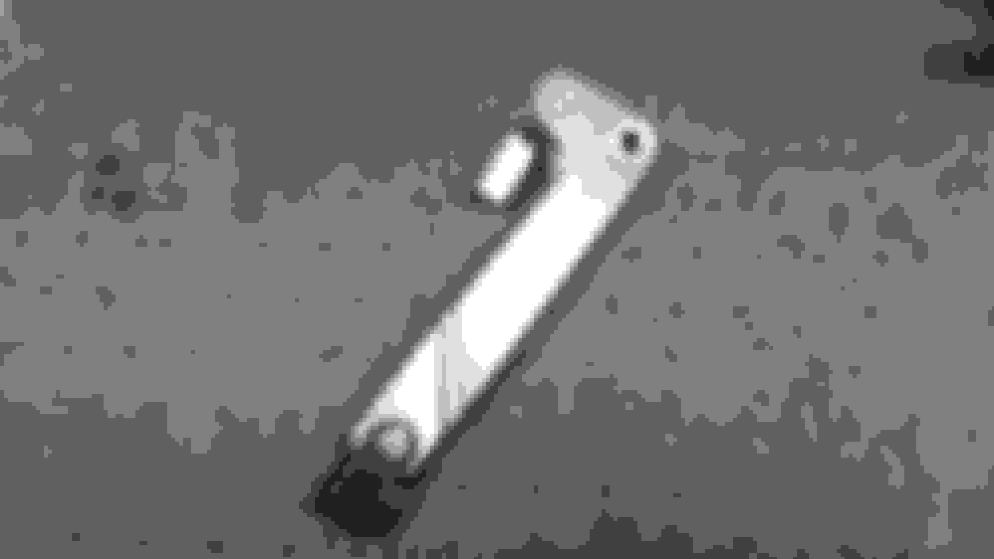
This is one of the brackets after I shaped it.
Here you can see the passenger side bracket tack welded in. The drivers side bracket is there. It is just on the other side of the drive shaft.
Here the rear of the tunnel mounting is complete. Don't pay any attention to the bolt with the nut on it that I used for mounting. I didn't have a bolt short enough so the nut is acting like a spacer. I will get new hardware later.
The drive shaft tunnel needs to come apart in a few pieces so that it can be removed from under the car when the body is in place. It would be easy to miss something with the body off like my current situation and end up with a design that could be difficult or impossible to remove once the car is finished. I am trying to avoid that. Every time I make a new piece I check to see if I can remove it by going down and not up. Later there will not be an up.
I thought I would share another design I used for through holes on tubing. You have seen me in the past use pieces of round tubing to strengthen through holes in square tubing for bolts to go through. Here I have some 3/4" square tubing that I want to put 7/16" bolts through. If I just drilled a through hole in it there would not be much square tubing left. There also would not be enough room to weld in round tubing to strengthen it for that size bolt. And I did not want to use larger tubing. So what do I do?
What I did first was I cut my 3/4" tubing to the correct length. At each end I drilled 3/16" holes in the sides about 2" apart. Then I took pieces of 5/8" square solid bar about 2.5" long and drove those into the ends of my 3/4" tubing. I used the 3/16" holes to plug weld the bar stock to the tubing. After that I have the luxury of solid ends to drill through holes in and the lightness and strength of tubing in the center.
You might ask why not just use a solid piece of 3/4" bar stock. You could. It would be easier. But there is a big difference in weight between a 10" piece of 3/4" bar stock and a 10" piece of 3/4" tubing with solid ends. And if you use solid stock for everything the weight will really add up fast.
The 5/8" bar stock fits inside the 3/4" tubing perfect. What ever size tubing you have, multiply the wall thickness by two and subtract it front the outside dimension. That size bar stock will fit inside your tube. In my case the 3/4" tubing has 1/16" walls. 1/16 times 2 is 1/8. 3/4 subtract 1/8 is 5/8. I also had to round the long edges of the bar a little for the bar to fit inside the tube.
Here you can see the 3/16" holes that I will use to plug weld the bar stock to the tubing. For assembly visuals the bar stock has not been driven completely in yet.
Here one end is finished. It has been welded and sanded, and the through holes have been drilled in for the 7/16" bolts.
Well, I finally have it done. I have a little bit of welding to finish up on the frame that I will finish when the trans and differential have been removed later.
The tunnel ends up being four pieces. The upper and lower tunnel halves shown earlier and two arms that are extended out toward the transmission. The lower tunnel half is bolted to the fabricated brackets near the differential shown earlier. At the other end I fabricated two gusset brackets which are now welded to the lower tunnel. The arms fabricated earlier bolt to the gussets and then to blocks welded to the transmission cross member.
I did not get a lot of pictures this time around. Same old thing. Cutting, welding, grinding, drilling, and tapping. The finished product is pictured below.
It ends up being pretty strong. I did not stand on it but it sure feels like I could. I will wait until it is fully welded before I try.
Don't worry, there is room for the parking brake lever below the drive shaft at the transmission cross member. I have some changes to show for that also later.
This might sound a little Scrooge-ish but about the only thing I like about the holidays is the deals.
I love all the free shipping and 20%, 25%, and even sometimes 30% off deals that i can get for myself. I just bought stainless steel brake lines, rear wheel bearings and seals, parking brake rebuild kits, etc., etc., etc. all at a discount
A while back I had bought an adjustable brake proportioning valve from SSBC and needed to find a home for it on the frame. I took a piece of 3/8" steel and drilled and tapped it for mounting the valve. Then I used my new brake lines to find the best location. I ended up in about the same location as the factory proportioning valve on my 1969. There should be plenty of room there. There is no more steering box in that area because of the rack and pinion steering and there should be clearance from the front suspension and exhaust.
I picked the location and welded the block to the frame. I will need to shorten and put a new flare fitting on the rear brake line and front passenger side brake line. I think I can modify the bends in the front drivers side brake line. And I will need to make two new lines to go to my master cylinder.
I am guessing that most of you are familiar with the parking brake mechanisms on C-2s. I think they were the same for 63, 64, 65, and 66, and then changed in 67. A pull handle under the dash attached to a cable. The cable runs under the car to mid frame and attaches to a lever. The lever is attached to a rod that goes back to another cable that runs between the left and right side rear parking brakes. When you pull on the pull handle, everything else pulls setting the parking brake.
When looking at the original design I did not have any problems with the cables or the pull handle. The cables are all heavy duty and are attached well to the frame. The pull handle is well mounted and a simple nice looking design that works really well. With the pull handle mounted to the steel structure under the dash you can give it a good solid pull to set the parking brakes.
Where I did have a concern was in the area of the lever under the car. It is attached to a bracket welded to the frame. The attachment point serves as a pivot. The pivot point in my case was a worn out bushing with a nut and bolt going through it. I did get a new bushing which was better but still loose. The bracket would wiggle up and down and all around.
The other concern was how the rod attached to that lever. The rod was bent at a 90 degree angle at one end. That end went into one of the holes in the lever and was held in with a cotter pin. This joint was also very loose fitting and wigglely.
The cable from the pull handle attached to the lever using a nice little clevis and a pin. This joint I liked.
O.K., how to make this part of the mechanism better? The pivot point would be much better with bearings and the rod connection would be better with a spherical rod end. I decided to make a new lever using thicker material. The old lever was 1/4" thick, the new lever is 5/8" thick. This gives me more material to press two bearings into the lever for the pivot. For the rod end I will be using a 3/8" shoulder bolt to attach it. The extra thickness gives me material to thread the shoulder bolt into. On the end that the cable clevis attaches to I machined the lever down to the original 1/4" thickness.
I will have this powder coated when I have the drive shaft tunnel done.
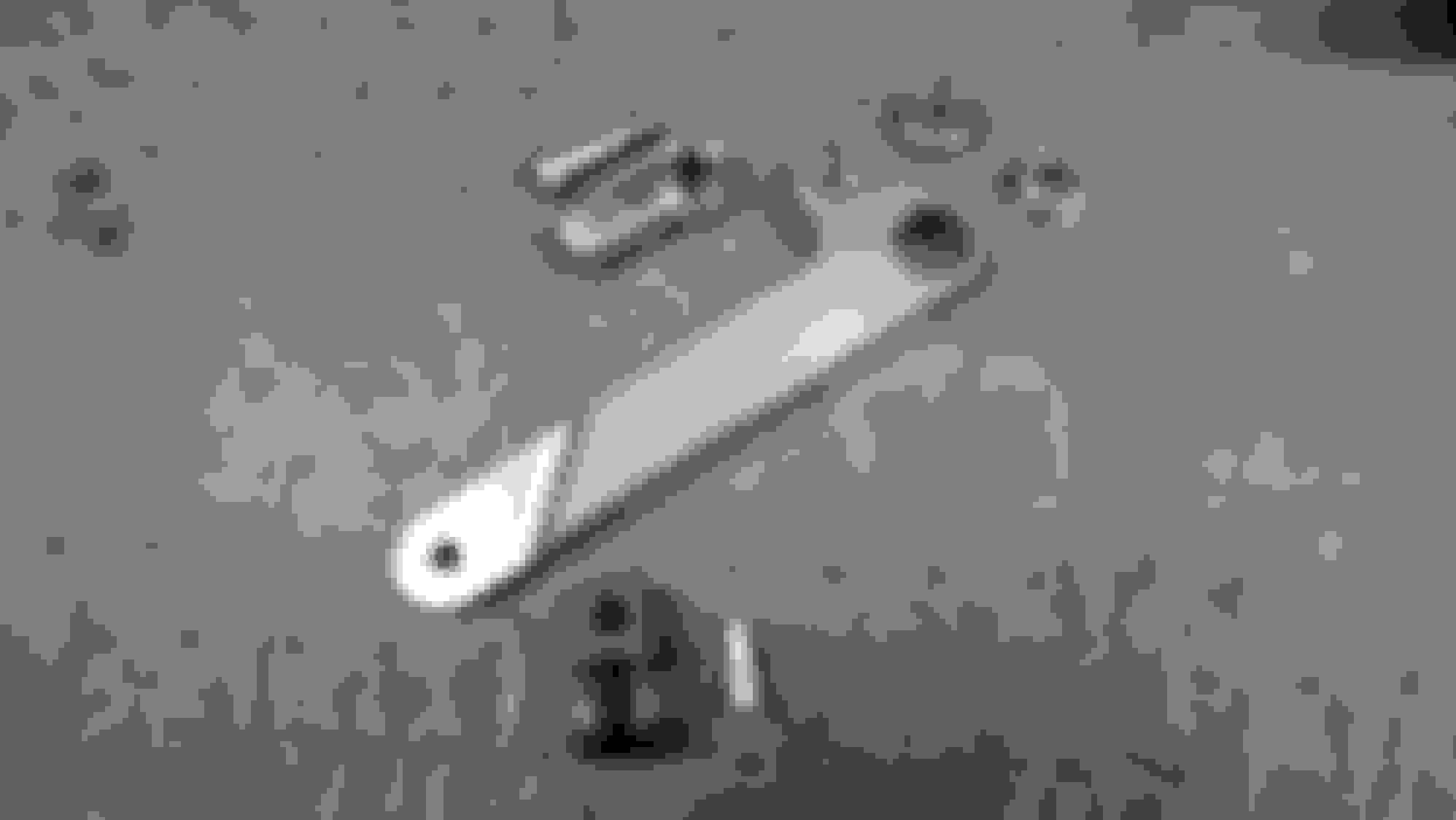
The original parking brake mechanism.
The new parts for the lever. New lever, two 3/4" OD bearings, ball end, shoulder bolt, original clevis and pin. Notice how the clevis end is thinner.
I have the under carriage parking brake lever done but there are a few other items I wanted to fix.
First the frame bracket that the lever attached to. It was not level. The old lever actually tilted away from the cable on the other side of the frame. I simply heated it up with a torch and bent it a little. FIXED!
Second, when I made my removable cross member the bracket on the frame that the cable attached to was in the way and I removed it. That bracket was a piece of thin metal that wrapped around the cable and was clamped with a nut and bolt. I was afraid that type of clamp would crack the powder coating when tightened anyway. The replacement is a two piece clamp that I made at the machine shop.
Third, the cable from the pull handle went through two holes in the transmission cross member. I welded in a steel tube between these two holes to push the cable through.
And last, when I was test fitting all this I noticed that the cable from the pull handle after it exits through the transmission cross member and is clamped down, it traveled very close to where the exhaust on the drivers side would be on its way over to the new level. Not sure how this should be. The cable exits the cross member pretty high and I moved the lever up to get more clearance. I ended up adding a small steel tube just large enough for the ball on the end of the cable to pass through. I welded this to one of my drive shaft tunnel supports to hold the cable up higher. I now have clearance to get a 2.5" exhaust pipe through there if needed.
This is the new clamp that I welded to the frame to hold the parking brake cable after it exits the cross member.
Here is the tube that I put through the frame for the cable. I welded it in, cut it off, and then ground everything smooth.
Here the cable and lever are installed.
Here you can see the small tube I am using to get more exhaust clearance. That is 2" PVC that I used to simulate exhaust.
Lets see, fiberglass car, seat belts anchored to metal bracket in fiberglass floor. What keeps the driver and passenger from flying out of the car in a collision when those brackets rip right away from the floor? Well I will tell you. A steel cable under the car attached to that metal bracket in the floor at one end and the frame at the other end. The inside mounting points for both the driver and the passenger are cabled together. That cable then hooks under a bracket welded to the frame just in front of the differential.
With the fabrication of the drive shaft tunnel I will no longer be able to use that center seat belt cable hook on the frame. I went ahead and cut that hook bracket off. I drilled two new holes in the frame, one on each side of the drive shaft. I then made two threaded inserts to weld into those holes. I will no longer be looping the inner seat belt mounts together. Instead I will get two separate cables and secure the inside mounts like the outside mounts.
This was the hook used to secure the two inside seat belt mounts in the car floor.
I made two of these threaded inserts to weld into the frame.
Here the original bracket is gone and my two new mounting locations are done.
Good news first. I feel I have the frame ready for stripping, "A" coating, and powder coating. "Again"
The bad news. On Friday (12/18/15) I decided that I was going to be ready and called about getting an appointment for the stripping process. They are not taking anything new until the first of the year.
On Thursday (1/7/16) I can drop it off and it should be done on Monday (1/11/16). That same day it will go to the company that will be doing the "A" coating and powder coating.
FYI, I had never heard of "A" coating until just recently. I had heard of "E" coating. The difference is "E" coating is a dipping process similar to chroming where the part is dipped in a tank and an electrical charge is used to attract the coating to the metal. "A" coating is also a dipping process but uses a chemical reaction to attract the coating to the metal. "A" coating is supposed to be better and is far less costly. After the stripping process this company will "A" coat my frame inside and out. They will then bake the frame to dehydrate it. Then it will be sprayed with powder coating (Satin or Semi Gloss Black) and baked again at a higher temperature to fully cure both the "A" coating and powder coating. It should be a well protected frame after that.
So, I will be spending some time completing other projects that need to be done until then. If I do manage to get something "Corvette" done before then I will certainly post it.
All mods done, everything ground, and ready for coating.
I have a local company that can do powder coating. They do not have a real big oven so they are limited to smaller parts. They also do not do any sand blasting so I blasted these parts in my cabinet. I had dropped these parts off just before Christmas and they did not think they would be done until next week because of the holidays. They ended up calling me two days later and said that they were done. They do a real nice job and all of these parts only cost $75.00.
Nice work on the safety features upgrades, your metal working skills are excellent. I am sure you will be happy to get that chassis black in black. Brian
Well, the frame has been stripped and is at the coaters waiting for "A" coating and powder coating. It may be done in a week. The below picture was taken after it was stripped.
I thought that while the frame was gone I would look at, and work on the rear trailing arms. Well, I looked at them and that was about it. I had ordered bearing kits and thought I would get the trailing arms assembled and ready for the frame. When I got the bearings they were all stamped "China" so I had to send those back. Found a supplier that had Timkens and ordered those.
I was cleaning up parts and noticed two things.
1. One of the rear spindle flanges was badly gouged around the seal surface. My fix for this I will talk about in a minute.
2. On both the rear spindle supports the holes for the lower shock mount bolt were badly worn. On one it is so bad that the knurl on the lower shock mount spins or has nothing to press into. Also the knurls on both the lower shock mount bolts are flattened or worn off. This problem I am still thinking about and I may try something new to fix them. Otherwise I may need new parts.
REAR SPINDLE FLANGE:
I can buy a new one for $70 but thought I would try to fix this one. I made a fixture to use in the lathe that the flange would just barely slip onto. I used a bolt and thick washer to hold the flange on the fixture. I then turned all the bad material off the end of the flange. The seal surface is supposed to be 1.6875 in diameter. I turned everything down to 1.5625 in diameter. I then grabbed a piece of 303 stainless steel and turned the outside diameter to 1.850 in diameter and bored the inside to 1.5615 so that it would press onto the flange. I then put the flange back into the lathe and re-made the seal surfaces. It turned out really nice. I almost wanted to do the same thing to the good one, NOT
Good flange, Bad flange. You can see the deep grooves in the bad flange. Notice that I also removed the old dust shield. It was also a little messed up. I will order a new one for the repaired flange. FYI, the seal surface on the good flange cleaned right up using a scotch bright pad and the lathe.
My fixture for holding the flange in the lathe.
The flange after removing all the bad material and preparing it for the stainless steel sleeve.
It turned out great. The shade of black is a little glossier than what I had before but that is O.K. There are only three or four parts left that are the flatter color and three shades of black under the car isn't going to hurt anything.
If I had it my way I would be out in the shop for the next 72 hours straight with no sleep living on 5 Hour Energy and Red Bull but my wife didn't think that was a good idea. Evidently I'm not that young any more.
I'm not going to go over every step again with anything that has been covered before. Over the next couple weeks I will update everyone with progress on getting the chassis back to the previous state. When I get to the rear end I will cover items that have not been covered before and start with new items from there.
The frame has been refinished and is back home.
Here you can see the difference in colors between old and new powder coat. The fuel tank support matched the old finish. It is a little flatter in shade.
Today I assembled the fuel line, some suspension rubber bumpers, the trans cross member and mounting bracket, the battery tray, and the upper front control arm mounting studs. More to come.
Great work, interesting find with the pinion angle.I wonder how many others have vibration due to incorrect alignment. What does the driveshaft tunnel do?
Brian.
Great work, interesting find with the pinion angle.I wonder how many others have vibration due to incorrect alignment. What does the driveshaft tunnel do?
Brian.
The drive shaft tunnel is a safety feature. For the driver, the passenger, and the car. Universal joints will break under high stress. Especially with a manual transmission and a high horse power/high torque engine. If you drop the clutch while revving the engine they could stress and break. If that happens the drive shaft tunnel will keep the drive shaft from coming through the fiberglass floor. There is evidence that this did occur previously in this cars life. (see picture below)
Now, I am not one to "Beat" on my cars, but I am going to want to drop the clutch at least once. And if I like it I might want to do it more.
For sure I will have to race my brother and his 1964 409 Impala. I plan on beating him.
The rear floor area has been repaired in the past near the differential. I suspect this was damaged when the rear universal joint broke.
I got the front suspension and rack and pinion steering back on. No issues.
I set the engine and trans in just to help get the differential back in and make sure everything was lined up. Again no issues. The engine will come back out later. Then back in, back out, back in, and back out etc., etc. for rebuilding and body clearance checks etc.
I am now looking at the rear suspension and so far, I am not happy. A lot of things for me to think about. More to come.
 11-22-2015, 02:54 PM


 Every time I make a new piece I check to see if I can remove it by going down and not up. Later there will not be an up.


 And if I like it I might want to do it more.