When you click on links to various merchants on this site and make a purchase, this can result in this site earning a commission. Affiliate programs and affiliations include, but are not limited to, the eBay Partner Network.
Nice to see a master craftsman doing quality work. Nice looking shop, too. Very impressive....you're going to have a heck of a nice car when you're done!!
At this time my rebuilt posi case more or less just dropped in. I used the stackable shims to set it up and did not want to use those for the final assembly. So, yep, I measured the set up shims and machined new solid one piece shims to use in the final assembly. I added .005" to each side to preload the bearings and surface ground them to the proper thickness.
I lowered the posi case down into the housing and placed the ring gear shim in first. I tried to move everything over toward the ring gear side as much as possible to make tapping in the other shim as easy as possible. I tapped it in. I had to work the posi case up and down a little but I got it in.
After final assembly everything ended up exactly as my preliminary set up. My back lash is at .008". Most everything I have read says .005". A friend that works on some of these for race cars says he sets all of his to .010". The instructions for the Richmond gears that I bought say to set it to .008-.012" so with all that I thought that .008" was a good compromise.
Everything turns nice. My rotational force was at just about 18 inch pounds.
I am satisfied that the wear pattern is as good as it gets. I was up with the pinion, down with the pinion, and all over the place with the back lash. I finally decided that this was the sweet spot
What I call the stackable shims that I used for set up.
This is actually one of the original shims that I was able to re-grind and use.
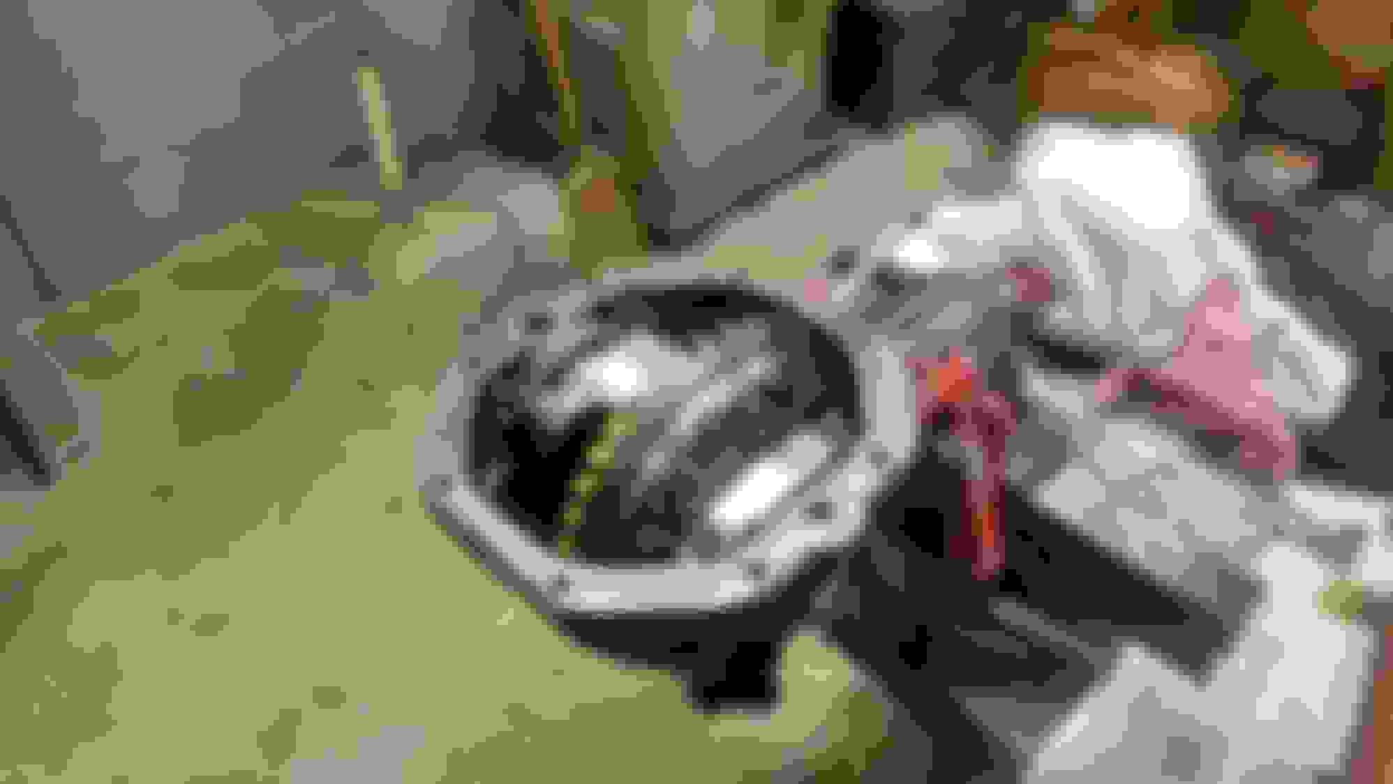
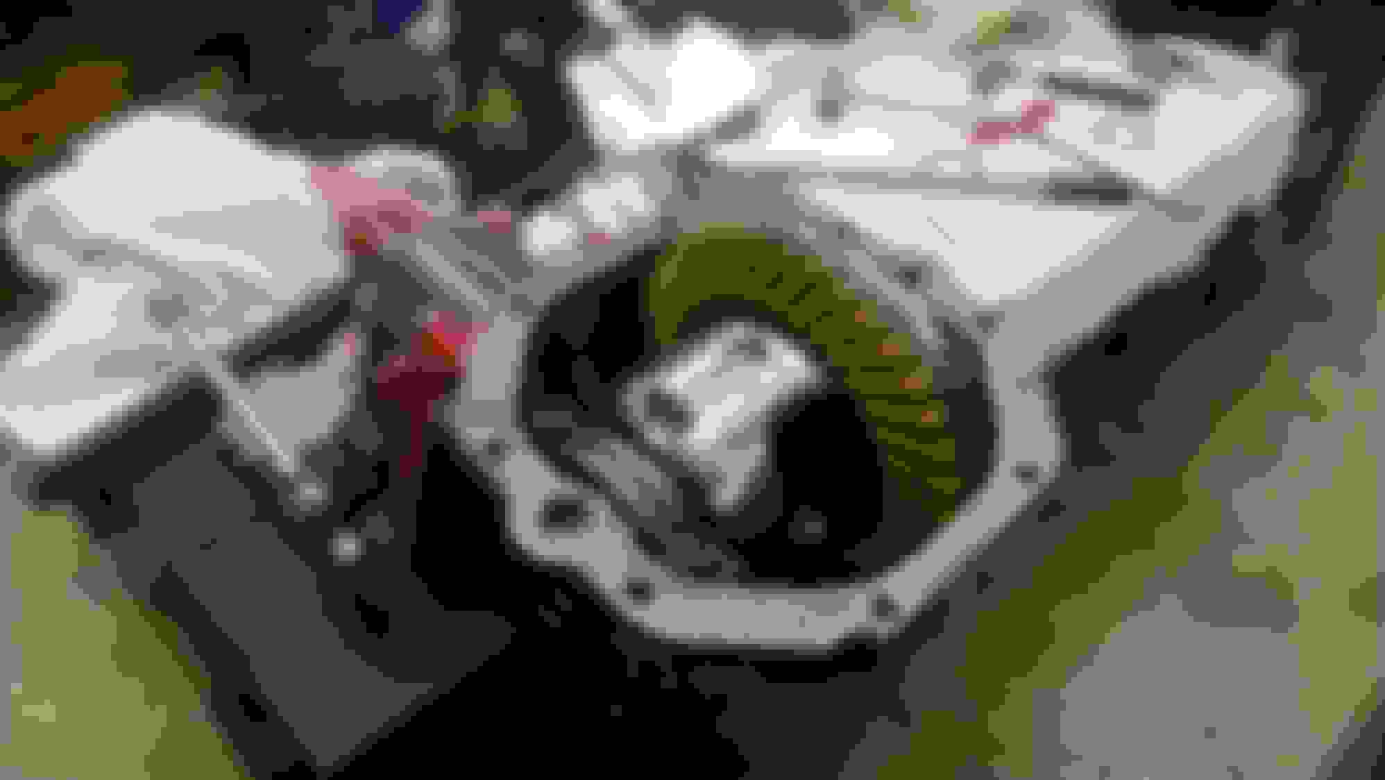
All assembled. Notice the Tom's bearing cap.
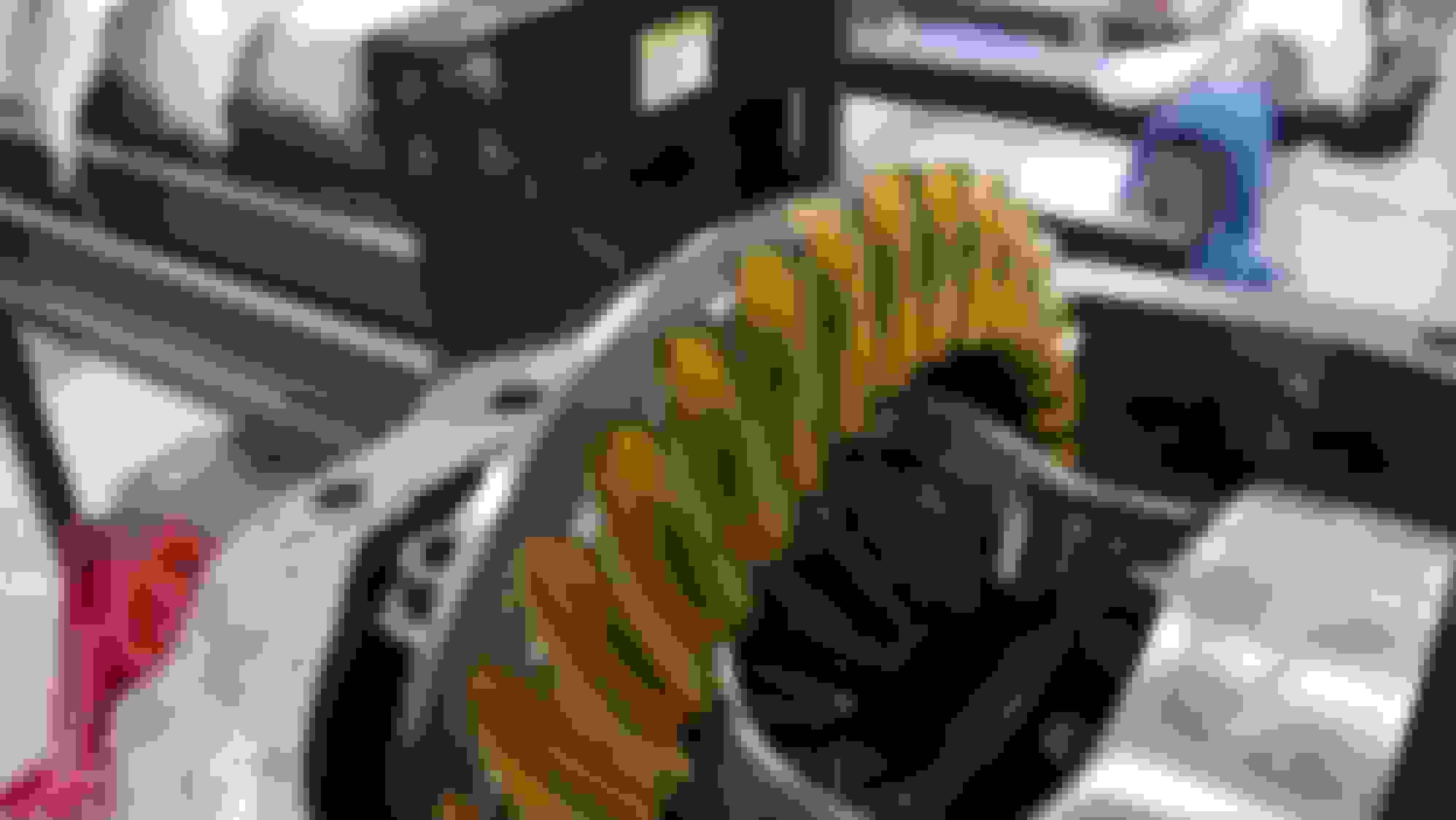
Wear pattern
I feel like this is something that was holding me back and slowing me down. A big accomplishment done and a big weight off my back.
Next I will get the side axles in and get it closed up.
I had installed the side axle bearings a while back. Here I have greased them real good.
I greased the back and inside of the side axle seals and installed them.
I greased the bearing and seal surfaces of the side axles and slid them into the housing. I had set the end play clearance earlier and only needed to verify it. Mine are set at .006". Then I installed the new snap rings.
The new breather was a slight pain to install. It presses in and is made of plastic so it can not withstand a lot of pressure on it. I used a wide bladed screwdriver and a small plastic hammer and slowly tapped it in going all around the base flange as I did. I managed to get it in without damaging it to much at all.
All complete, I installed the housing cover and lower support bracket. I used stainless steel hardware and did not use lock washers. I used flat washers and thread locker instead. I did not want the lock washers to dig into the powder coating. I actually used red thread locker on the cover bolts and the blue on the lower bracket.
Next I am going to temporarily install this on the frame and investigate fabricating a drive shaft loop. There is evidence of the drive shaft breaking in the past and coming up through the floor in the rear of the car. Although I do not plan on beating on my car all the time, I would like to be able to get on it or pop the clutch every once in a while and not worry about the drive shaft coming up through the bottom of the car.
Area in driveshaft tunnel where I am pretty sure the drive shaft broke and busted through the floor.
Looks good! Interesting experience. How did the install of the ring side case bearing cap go? Does it have to be surface ground for correct bearing crush?
Brgds,
Rene
Looks good! Interesting experience. How did the install of the ring side case bearing cap go? Does it have to be surface ground for correct bearing crush?
Brgds,
Rene
Yes it did, or at least in my case it did. I also had to oblong the bolt holes about .010" on each side to get them to line up and go in without interference. I could have forced them, but that did not seem like a good idea. I am sure that each case would be a little different.
When I had the frame sandblasted and powder coated the first time the rear body mounts did not really hold up too well. They ended up being pretty corroded around the center hole and the sandblasting eroded it all away. If you have read the blog by "steveale" called "1965 Restoration" you saw how he fixed his using big washers. I could not find the right washer with the right inside diameter for the body mounts so since I have access to the right machines I made my own. It was the same process as Steve used after that. Cut away the old material, weld in the new, and grind it smooth.
This is pretty much how both rear mounts looked after the frame was sandblasted and powder coated the first time.
I used a torch to burn the powder coating off and a Scotch Bright pad on my die grinder to clean it up. This way I could cut and weld on it.
I removed most of the material with my plasma cutter and used my die grinder to clean it up and make the washer fit.
I welded in the new material.
Then ground down the welds and smoothed it out.
Later I have some things to do on the bottom of the frame so when I flip it over I will weld and grind the bottom of these also.
Well summer is over. The outside projects are done for the year except for some fall clean up. I should be able to get back on the car now a little more regular.
A while back I had test fitted my rack and pinion kit and found that I had a clearance issue around the input shaft and the left side frame engine mount. You can see it in the picture above. Well today I fixed that issue.
First I clearanced the frame motor mount. I cut out most of it with a plasma cutter and then used a grinder to finish it up.
I then cut a piece of 1/8 steel plate to reinforce the bottom of the motor mount and tacked it in.
I test fitted the rack again and checked hose clearances. It looked good.
I finished welding it in and then ground the welds smooth.
Previously I made repairs to the rear body mounts on the frame. I had cut out bad material and welded in new material. At the time I was only able to weld and grind the top of the mounts. Today I flipped the frame up and was able to weld and grind the bottom of the mounts. This finishes those repairs up.
Today I did a crap load of grinding on the frame. I went around all sides, top, and bottom and ground down any antique weld spatter and high welds. I did not smooth the weld out. Just knocked down the high spots. After I had it powder coated the first time it looked great but I still noticed the weld spatter so I decided to get rid of it this time around.
After that I spent a couple hours cleaning up all that dust. Holly crud that stuff gets everywhere.
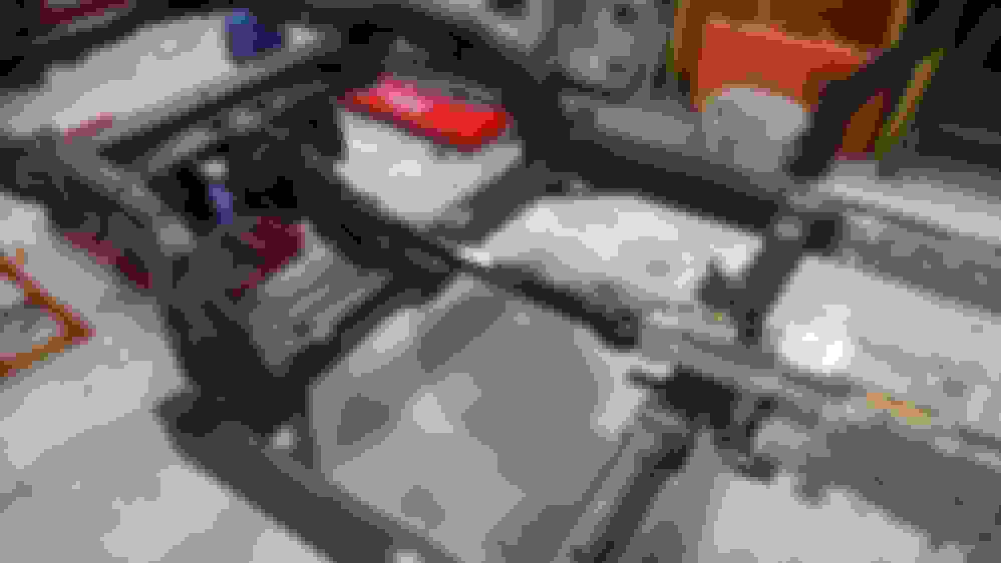
Then I got the frame back on my jack stands and got the engine, transmission, and for the first time the rear differential and drive shaft. Next I will order some steel tubing and start designing and fabricating a drive shaft tunnel.
I didn't crank the bolts down for the differential cross member cushions. The original ones were a pain to get lose from the frame. The cross member still has to come back off for the new powder coating. I lubed them up with anti seize hoping that I will be able to pop that cross member back off later.
Man that's impressive steel work your doing.
I like your attention to detail.
I'd like to make a suggestion. When I did my resto in 2008 I didn't include a removable cross member at the time. That was a mistake. To get the trans or clutch out you have to yank that BB. So when I had the engine out this past winter I did make a removable cross member. It really made the job easier for future problems.
Anyway great job so far keep posting.
65-StingRay
You know, your not the first person to suggest that. I keep going back and forth on the idea. I guess I will look into it a little more and give it more consideration.
Well, after having had the suggestion of making my transmission cross member removable by several people, I have spent the last few days researching the idea. I looked at all the designs I could find out there, read all the different threads, read about pros and cons. And well, the picture below shows what happened this morning.
All gone
I decided to go for it and cut it out this morning. And I decided that I wanted to do this before the drive shaft tunnel because the removable cross member may change that design.
After looking at all the other designs out there I want my finished product to be clean looking. I do not want to see welded plates or a lot of hardware when it is done. I would try to explain what my plan is but without drawings or pictures it would be hard. So I will be sure to post everything for you to see.
I wanted the joint to be at a 45 degree angle instead of straight. This will make removing it and aligning it when installing it easier. I also looked at maybe moving the exhaust tunnels out from center more. I thought that if I could move the exhaust out more I might be able to make the section in between them larger and then removable. I though then I would be able to remove the removable section without removing the exhaust and have plenty of room to work. This idea was quickly shot down when I realized that I would probably have clearance issues with floor pans if I moved the exhaust out. On the bright side only having to remove the exhaust, drive shaft, and probably parking brake linkage to get the trans out is a lot better than having to remove the hood, radiator, engine, and everything attached to it.
Below is what I got done of my mounting design today. It might give you some clues to my idea.
O.K., I have the transmission cross member done. I am going to post several posts to show what I did and how I did it.
From my last post you can see one set of two sets of plates that I started with. I drilled and tapped them as pairs. The idea is to machine them to fit inside the frame where it is cut and weld them in place. It would have been easier if the frame tube was somewhat square in shape but it is not. One corner is very round. Each pair is made from one 3/8" plate and one 1/2" plate. The 3/8" plate is drilled for a 1/2-13 machine screw to go through. The 1/2" plate was drilled and tapped with a 1/2-13 thread.
I started by machining the top and bottom edges of each set to a 45 degree angle. Next if you look at the cross section of the cross member it is one "U" shaped channel inside another. So at the bottom of the cross member the inside gets wider as it changes from one channel to another. So I needed to notch the top portion of both sides on each set of plates to make it narrower. After that I used the mill to shape the large radius at the top and the belt sander to clean everything up and shape them until they fit inside the frame.
I used the mill to machine the top and bottom edges of both sets of plates to 45 degrees.
Using the mill to rough the large radius on each set of plates. The radius needed to also be at a 45 degree angle. This will be cleaned up on the belt sander.
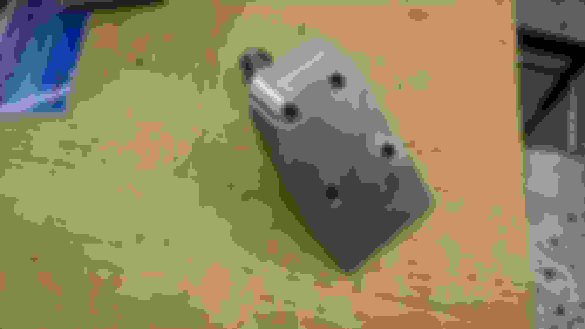
This is the first set after I roughed the large radius.
Getting the frame ready. I should step back a little and explain about cutting the frame. When I cut the frame I used tape and marked the angle the best I could using a carpenters square. I then cut it using a abrasive wheel and sawsall.
I wanted to make sure that I had the plates welded in the frame at as close to a 45 degree angle as I could. Now this is not an ideal method, but it worked for me and for what I was doing. I used a 6' level and leveled the frame on the jack stands. I usually have it leveled anyway but went a head and checked it and made some adjustments. Next I raised and leveled a sissors jack under the cut section of the frame. I used that, a carpenters square, and welding magnets to align and tack weld in both of the 1/2" threaded plates into the end of the frame. I only tack welded them in three spots. I may need to adjust them later.
Frame marked for cutting.(Sorry that it is blury)
Frame after it was cut.
Aligning and tack welding the 1/2" threaded plates.
O.K., this is where all the work really was. I started by cutting it to the correct length. Before I had cut it off the frame I had taken a measurement from each side to the center. I put the cross member back in where it was cut from in the frame, aligned it back up, and measured each end to determine how much needed to be cut out. It ended up being about a 1/4" from each side. I did this with a band saw at the machine shop. This gave me really clean edges to work with. I wish I could have used it on the frame.
O.K., by now you might be wondering just how this is going to bolt together with the hardware ending up inside the frame cross member. Some of my buddies said to just cut holes on the bottom of the cross member to access the bolts but I wanted a cleaner nicer look than that. My idea was to weld in tubes for each bolt hole for access.
I used a nut bolted to the plate to locate the tube while welding it in place. This kept the tube centered around the hole. Just a little sanding on the nut and the tube slides right over it. I welded the tube in place, unscrewed the bolt, and then the nut pushed out the end.
Here the first tube is ready to weld in place on the plate.
I used a section of tube cut at a 45 degree angle to mark the cross member. I needed to mark it and cut it for the tubes to come out the bottom.
I used my plasma cutter to cut holes for the tubes to fit up through the bottom of the cross member. As you can see, I am not the best at using the plasma cutter. But I do say, it is better than an acetylene torch for cutting. When needed, I used a die grinder to adjust the opening. I first fit the two long tubes to the plate and into the cross member. Then added the two short tubes to the plate and cut holes for them.
All 4 tubes in. The tubes are welded to the plate and the assembly fits in, but is loose, not welded to the cross member.
 08-21-2015, 07:30 PM