1972 Wiper motor wiring
 05-10-2010, 02:53 PM
#1
Instructor

Thread Starter

Member Since: Nov 2006
Location: TX
Posts: 122
Likes: 0
Received 0 Likes
on
0 Posts

The wiper motor on my 72 has been jury rigged, it looks like to run at only high speed.
I have the wiper diagram from the Willcox website, but need to know how the connections are made to the terminal block inside the motor case, that the motor control connector goes to.
The motor control connector has 3 wires, GRN, YLW and BLU. The RED power wire for the motor is supposed to run through a grommet, and connect to the terminal block with a resistor, mounted inside the case. Instead it has been removed from the grommet, and spliced directly to the BLK/pink wire coming from the motor.
Looking inside the cover, I see that the BLK wire from the motor goes to the terminal that the GRN wire on the connector goes to, and is connected to one side of a wire wound resistor.
There are no other connection to the terminals inside the case that go to the YLW and BLU wires on the connector.
Does anyone have a motor that they can look inside the case at the wiring for me?
There are two small wires presently on the inside terminals (that go to the YLW and BLU wires on the connector) that have been cut, and are not connected to anything.
I think the BLK/pink wire from the motor goes to the middle terminal (YLW wire on the connector).
It also looks like the pigtail on the other end of the resistor should go to case ground.
I don't know where the RED power wire is supposed to connect, and where the two small red cut wires are supposed to go.
 05-10-2010, 04:11 PM
#2
Race Director

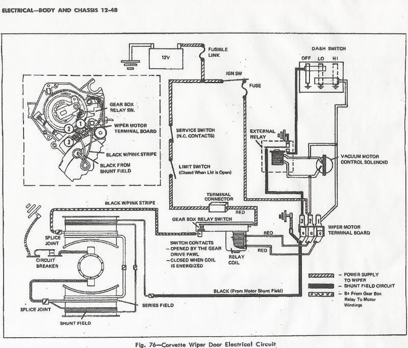
I'm sure Ernie can tell you exactly but here is a diagram I had in my Photobucket. I believe this is 69-72. I've seen several pics here on the forum of the inside wiring.