
Wiper Door Vacuum
 04-12-2002, 10:29 PM
#1
Intermediate

Thread Starter

Member Since: Apr 2002
Location: Poynette Wisconsin
Posts: 32
Likes: 0
Received 0 Likes
on
0 Posts
Has anyone had a problem with the wiper door staying open on their vette? When I turn my wipers on, the door will open, but will not close when I turn the switch off. When the engine is running, with the switch off I can't even close the door by pushing on it. Only after I turn the engine off am I able to close the door by hand. Does anybody have a best guess as what the problem could be? The headlights work fine. The car is a 71 coupe. This is my first post on the forum. Thanks in advance for any help.
 04-12-2002, 10:36 PM
#2
Race Director


You have come to the right place to find the correct answer. Someone on here emailed me a copy of a vacuum diagram that they had. Maybe you have a line that is crossed somewhere.
Do you have a hand operated vacuum pump? If so you can check your wiper door actuator to see if it will work on the hand vacuum. This should prove the actuator to be good or bad.
Maybe someone else can be of more help. I printed the diagram and deleted the email of the diagram a long time ago. Someone once said that the doctor rebuild site has the diagram on the web. Try checking there.
04-12-2002, 10:41 PM
#3
Intermediate
Thread Starter
Member Since: Apr 2002
Location: Poynette Wisconsin
Posts: 32
Likes: 0
Received 0 Likes
on
0 Posts
Thanks for the tip. I don't have a hand vacuum pump, but I may go buy one. I will have to look for the vacuum diagram you mentioned. Nice looking car you have!
04-13-2002, 12:45 AM
#4
Team Owner


Check to see if you have a hissing sound coming from under the drivers side dash on the Tach side. There is a selenoid that "changes" the electrical signal from the wiper switch to a vacuum signal to open the door. This is a two way electrical valve and if it sticks open then the door will not close (until you shut off the engine and close it by hand) This valve can also get dirt in it and cause it to leak vacuum. I had this very same problem and I removed the selenoid and took it apart...see my post http://forums.corvetteforum.com/zerothread?id=271473
This should help. Another symptom....when you start your car does the door open the close? Also does the door open after you have been driving it then shut off the engine?? These are classic dirt in the selenoid symptoms.
Unfortunatly this part is no longer made but you can find used ones for around $90.00. I bought the rivet puller and rivets for around $12
Hope this helps
John
04-13-2002, 12:57 AM
#5
Intermediate
Thread Starter
Member Since: Apr 2002
Location: Poynette Wisconsin
Posts: 32
Likes: 0
Received 0 Likes
on
0 Posts
Thanks John. Those symptoms sound very familar. I followed the link you left. Seems very helpful. I guess I know what I have planned for the morning. Is this very hard to get at? Do I have to pull the dash apart? I sure hope this will solve it. Any suggestions are greatly appreciated. Nice roadster you have!
04-13-2002, 01:07 AM
#6
Team Owner
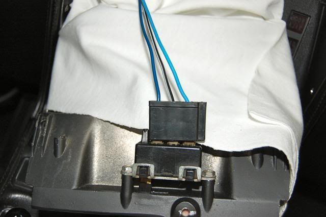
If you read the other post and have the standard steering wheel not Tilt/Telescopic then its fairly easy to get to. It is attached to the back of the tach with two 1/4 inch bolts (I think they are 1/4 I can't remember, they may be 5/16) Kinda a pain to get to. You will see the selenoid. It will have 2 vacuum hoses attached to it and also an electrical connector. I marked my electrical connector with tape just in case it matter which way the connector is attached. If my digital camera was working I's take a picture and send it to you sorry. You will figure it out the fix is actually easy. The hard part is getting it out and back in. Referance this post and the other one and that is pretty much it.
Good luck
John
Good luck
John
04-13-2002, 09:58 AM
#7
Intermediate
Thread Starter
Member Since: Apr 2002
Location: Poynette Wisconsin
Posts: 32
Likes: 0
Received 0 Likes
on
0 Posts
Thanks again John. I am going to try what you suggested this morning. I will let you know if this works later.
04-13-2002, 10:16 AM
#8
Team Owner
OK, on both the headlights and the wiper door, the basic theory is the vacuum relay with the 3 big hoses going to it, has also a small hose....that small vacuum hose is the controll hose, changes the 'state' of the large hoses, to determine if it's up or down....
SO, the relay being spring loaded, is allways a 'suck down' that's what I call it anyway....if NO suck (vacuum) is at the controll point of the realy, the relay is telling the headlights/door to open up....
SO the trouble is, you have no vacuum at the controll point...this can be from various causes, just find the controll realy on the passengers' fender liner, and go from there....check the obvious points first...like loose hoses maybe under the dash, listen for sucking sound from loose hose,...engine running obviously....check that vacuum switch under/near the pass wiper blade base...
it has ONE hose off it, to releive vacuum...going NOWHERE under the engine compartment, it's supposed to be that way...
GENE
04-13-2002, 01:25 PM
#9
Former Vendor
Member Since: Apr 1999
Location: ECS Sales & Service Advisor
Posts: 7,607
Likes: 0
Received 1 Like
on
1 Post
Cruise-In III Veteran
Cruise-In V Veteran

I posted this in the other thread but I thought it would help you to so here it goes....
Here is a great expliantion of the entire wiper system that was posted here by Wayne Elwood, the Editor of Shark Quarterly (may it rest in peace! - What a great mag it was) (Wayne do you still hang around here????)
I think it's a "must have" for every early C3 owner....
------------------------------------------------------------
Understanding Your Windshield Wiper Circuit
(non-pulse only)
by: Larry Ingram
(Ghosted image of electric chart for
title page)
One of those seldom understood parts of the 68-82 Corvette is its wiper
system. This is particularly true of the 68-72 versions which had a unique
door system interconnected to the electrical circuit. If the vacuum part of
the door opening mechanism fails to open the door fully or the wipers don't
park properly, then the whole set up becomes very difficult to get back into
proper operation.
Since the Editor's "Project "68" needs this work as part of the restoration,
as well as the fact that the proper service manuals are hard to understand,
I thought our readers might like to have the benefit of an "improved" repair
guide.
Step one, as usual, will be to briefly describe each component as well as
it's function. Then I will describe the entire circuit in the simplest
language I can manage. I won't be able to cover every detail but I will give
you a solid grounding -- in more ways than one.
Wiper Switch - Most people expect the switch to be the power source but it
isn't. It simply grounds the wiper motor and / or the washer pump. If the
pump is wiper motor mounted it grounds a relay.
Wiper Motor - The motor is of a two-speed design using different field
windings to produce the two speeds. Incorporated inside the gear reduction
area of the motor is an electrical park relay and a small resistor. The
relay serves multiple duties and can be the source of most of the electrical
problems. Also as part of the motor (until about 77 or 78) was a mechanical
washer pump driven on demand, by the driver, by the motor's gear reduction
unit.
Park Relay - The park relay, when energized, allows the motor to turn. It
does this by simultaneously releasing its gear driven transmission and
closing a set of points which are concealed within its plastic housing.
(photo # 15 - optional as per space) This then allows battery power to the
field windings; this power keeps it running. Internally, the motor has a
field winding in series to its armature, as well as another winding called a
shunt. The shunt when energized limits RPM, causing the slow speed mode of
operation. The high speed current path is powered through the park relay's
points, through the field to the positive brush, and through the armature to
the negative brush, from that brush to ground, via an internal circuit
breaker. When the wiper switch is turned off the relay drops a hook (pawl)
into the path of the rotating reduction gear, stalling the movement as well
as pushing the points open to stop the motor.(photo #18) showing park pawl
assembly) Observing the rotation of the shaft where the linkage is attached
will show how the wiper arms get parked lower than in the normal sweep area.
The shaft parks in an offset path relative to where it is rotating during
normal operation. This is accomplished inside the gear mechanism by a slot
that controls shaft position.
Limit Switch - Used only on 1968-72 cars this switch controls main power to
the wiper motor, and is actuated by a linkage connected to the wiper door
opening mechanism. The switch is open (off) until the wiper door opens to
about 90% of its travel. Only if the wiper door is open should there be
power to the motor on this circuit.
Override Switch (1968-72 only) - Placed under the dash below the steering
column is a rotary switch as well as 2 vacuum switches. These switches allow
servicing the related components, since the wipers will park and be hidden
by the door even if the key is turned off, if not otherwise controlled by
the override switches. Many a frustrated owner has had the experience of
(apparently) failed wipers because someone turned the rotary switch to see
what it operated. If the wipers were off at that time no response was
noticed; but the first time wipers are demanded they won't work, if the
switch was left open.
Electrical Control Relay (1969-72 only) - A relay mounted inside the
console to the right of the radio, used to supply wiper switch information
to the motor circuit. The relay is needed to allow parking of the wipers
when the key is turned off.
Vacuum Circuit - 1968-72 cars featured a heavily advertised feature touting
the missing or concealed wiper blades, actuated by a vacuum circuit. The
vacuum circuit consisted of a large vacuum motor to open or close the door,
a vacuum relay used to send vacuum to the motor, an override switch under
the dash, an electrical solenoid behind the tach to send the vacuum signal
to the relay and an interlock vacuum switch moved by the right hand wiper
arm. Connecting all these parts are several feet of vacuum hose which can
rot, be pinched, knocked off, or simply connected incorrectly. Problems tend
to go un-noticed until the driver is caught in a downpour.
How Does This System Work
So, with these basic system components, the question now becomes, "How does
this system work?"
I will begin by describing the operation of the wiper door system. The door
is opened or closed on demand using engine vacuum, stored in a tank under
the left fender beside the master cylinder. The tank is evacuated (supplied
vacuum) by the running engine through a check valve and a filter. Vacuum is
directed as two separate circuits to the vacuum relay: one operates the
relay and one operates the vacuum motor (tank or double pie plate part
mounted above the heater on the firewall, just to the left of the hood
catch.) The relay is a spring loaded valve that can be pulled against the
spring using vacuum on a diaphragm. This causes it to direct vacuum from the
center port to one side of the vacuum motor while opening (ie: venting) the
motor's opposite side to atmosphere. Four hoses will attach to it, three
large and one small one (it's signal). (use photo # 4) When there is no
signal, engine vacuum is applied in at the large center nipple, routed
internally to the nipple farthest from the diaphragm end and via a hose to
the vacuum motor to open the wiper door via its linkage. When this happens
the top nipple is vented to very bottom of the relay where there should be a
foam filter in a square plastic framework. All of this is reversed if vacuum
is sent through the signal hose to pull the diaphragm up; the valve pulls up
opening the lower port to atmosphere and routing vacuum to the top nipple.
A vacuum signal is used to control the opening or closing of the wiper door.
This signal is applied to the relay's diaphragm to close the door, or the
signal gets blocked off and the diaphragm is vented to atmosphere to open
the wiper door. This job is done using a multiple switch path. The control
circuit consists of three switches in series, the interlock valve under the
wiper arm, the over-ride valve, and the solenoid valve. (photo # 20) This
solenoid is wired to the wiper switch and therefore whenever the switch is
turned on it is supplied a ground. The solenoid is live whenever the key is
on receiving its power through the wiper fuse.
Here Is How It Works
Vacuum is applied to the vacuum relay diaphragm. Engine vacuum goes to the
interlock valve via a hose. If it's depressed by the wiper arm, the vacuum
continues via another hose to both the underdash over-ride switch and vacuum
control solenoid. Either or both of these shut the vacuum off when
activated, and simultaneously vent the vacuum that was in the diaphragm thus
allowing the spring in the vacuum relay to switch vacuum to the opposite
side of the vacuum motor and open the wiper door. Remember that the relay
opens a vacuum path between two nipples and also vents the remaining nipple
to atmosphere; it does not just switch vacuum only. When the wipers or the
ignition is turned off, vacuum from the reserve tank will again be applied
through the interlock valve, after the electrics park the arms, through the
solenoid to the relay, unless the over-ride switch is pulled down. When the
vacuum pulls the relay's diaphragm and piston up, it directs vacuum to the
vacuum motor as well as venting the opposite side of the vacuum motor. It
would be difficult to pull the motor diaphragm if the opposite side was
sealed. Of course, if the override switch is pulled down the door will
remain open as the vacuum path to the relay diaphragm is blocked.
By using vacuum valves in this way GM engineers were able to prevent changes
in engine idle due to vacuum leakage below the carbs butterfly valves. If
the hoses get reversed at a switch or valve, then whenever it gets activated
a small vacuum leak is introduced and some change in idle should be noticed.
Now I Will Explain the Electrics
To begin, I will explain the basic set-up for the 1973 and later, and then
add in the extras used in 1968-72. Even though these latter years had
differences, there was a basic set of principles which applied.
As stated earlier, the wiper switch is only a ground source. The motor and
washer pump are supplied power on a yellow wire that is fused by the wiper
fuse & powered through the ignition key. If the key is on, then power is
supplied to one side of the park relay (hidden inside the area covered by
the washer pump or if the pump is under the jar then behind the cover over
the gear drive). The other two terminals of the motor control circuit are
wired as follows: terminal # 1 is used to create the high speed, while
terminal # 3 controls slow speed as well as the parking command, when the
wipers are switched off. These commands are received as follows, the wiper
switch grounds both # 1 and # 3 for low speed and only # 1 for high speed.
When the ground is provided the park relay magnetically pulls back the park
pawl, allowing the motor to rotate the gear reduction unit. Simultaneously,
a set of points inside the relay close allowing the power to the motor
field, armature and brushes which are all in series to each other, with one
brush being connected to ground via an internal circuit breaker. If the
points fail to close, are burned or pitted, or a brush is worn down or
simply hung up by rust or corrosion, then nothing happens other than the
pawl moving. IMPORTANT NOTE: Because the wiper motor is mounted to a
plastic body there is a ground wire attached to a terminal on the gear
cover. This can also get knocked off, corroded or it's other end
mis-installed. Whenever there is a problem begin by verifying the ground.
(Photo # 23 # 6 shows under dash override switch with pen pointing to
"vent to atmosphere" hole which is only visible with the override switch
pulled down in the "open" position - ie: to hold wiper door open)
1968 version - The circuit for 68 is unique and so far I have not found it
in any service manual so this information was arrived at the hard way, 1
wire at a time on a car that had been messed with. The motor in 68 is not
grounded conventionally. The ground brush is wired to the under dash rotary
switch. This prevents using any other year motor without making internal
changes. The park relay turns the motor on and off but the power to run the
motor comes through the wiper door actuated limit switch (live at all times,
fused at the horn relay by a fusible link ). This wire goes into the motor
and attaches to one side of the park relay point set, through the points,
field, brushes and armature and then back out of the motor into a harness
that takes it to the rotary switch, the other side of which is grounded
(switch closed). According to my notes there is a three-wire plug coming out
of the motor, red is power, brown goes to the vacuum solenoid on the back of
the tachometer (photo # 3 - optional for space), and a light blue which
changes to a black going to one side of the limit switch, through the switch
it changes to a brown, then to a brown with a white stripe, and ultimately
goes to the rotary switch. Each of the color changes takes place at terminal
plugs. Why it kept changing colors I don't know.
1969-72 version - To the best of my knowledge these years were all the same.
In 1969, an inside console relay was added, as well as grounding the
armature brush internally rather than via the rotary switch. The new circuit
put the rotary switch in series with the door actuated limit switch. This
means that power must flow through the switch and is easily checked with a
test light at a connector going into the motor (heavy red wire). The wiper
switch controlled the motor using the console mounted relay as follows.
Energizing the relay switches motor control to the wiper switch, closing a
set of points inside the relay case which grounds the motors # 3 terminal to
cause low speed operation. If the wiper switch is moved to high then both #
1 and # 3 terminals are grounded causing high speed. When the wiper switch
gets turned off, the relay looses it's power and the spring loaded point arm
opens completing another ground circuit. This grounds the # 3 terminal
allowing slow motor speed. Because the park relay lost its power when the
wipers were turned off, it has dropped its hook out to stop the gear in the
parked position, which (as it parks) will also open the field points within
the park relay. This stops the motor. Ultimately the wiper door will close
and disconnect the main feed by opening the contacts in the limit switch.
In this circuit set up the vacuum solenoid is wired in parallel to the
relay. Whenever the relay is energized so is the solenoid. The control relay
is wired, using 5 - 18 gauge wires, as follows:
- light blue, wired in parallel to the wiper motor # 1 terminal, the wiper
switch high speed terminal, and the vacuum solenoid;
- yellow, wired in parallel to the wiper motor # 2 terminal, the vacuum
solenoid, and the wiper fuse;
- light green, to the wiper motor # 3 terminal to provide the ground
necessary for low speed operation;
- black, to the wiper switch for low speed, connected by the relay when
energized;
- black /white stripe, to ground, this is connected to the light green if
the relay is not energized.
The wiper switch used for all years has three terminals, # 1 grounds the
washer pump when the switch is depressed, # 2 is for low speed, and # 3 for
high. In actual fact both # 2 and # 3 are connected to ground for low
speed. This translates to grounding # 1 and # 3 at the motor to get low, or
# 1 for high. For the years 1968-76 the wiper switch receives its ground
from the white metal dash cluster housing the gauges, later years had a
proper ground wire. Note: Many of these housings have been broken by
improper dash assembly causing intermittent operation. If your bezel is
broken at the sides just above the gauge area I suggest that you add a
ground wire directly to the switch. In some cases I, as well as others, have
received a substantial shock touching here during troubleshooting. I guess
the motor builds up like a coil looking for a path to ground.
So, that's it. A rough guide to the whole wiper/wiper door issue. When I
took on the assignment I thought I knew pretty well how the whole system
worked. Once I started looking at the service manual, however, I realized
how many important facts were left unstated and how badly the circuit
diagrams of the day explained the situation. I suspect that a lot of other
"guides" are equally poorly described, because this is a complex system. But
how are you going to fix it, if you don't know how it is supposed to work?
If you want to add any important points from your experiences, I welcome
your comments.
----------------------------------------------------------------------------------------
Hope it helps!!!
Mike
04-13-2002, 10:58 PM
#10
Intermediate
Thread Starter
Member Since: Apr 2002
Location: Poynette Wisconsin
Posts: 32
Likes: 0
Received 0 Likes
on
0 Posts
Wow! What an incredible amount of help and information. I am going to keep this priceless information in case I have future problems. The good news is I found the solenoid. Not the easiest part to get off. As John suggested the solenoid was stuck. I took it apart, cleaned and lubed it put it back on and the door now closes. It works every time. Now I know what the other person meant after he fixed his and he said he almost cried when it worked. The only problem is that when it closes, the passenger side stays up about a half of an inch. Hopefully I can adjust the actuator and get that to pull down a little further. I had the actuator off a couple of times and it probably lost the adjustment? Is there a rule of thumb for adjusting that? Again I can't thank everyone enough for all the help.
Next step is to replace my gas tank. I think I will post another question on that topic.
Thanks,
Scott
Next step is to replace my gas tank. I think I will post another question on that topic.
Thanks,
Scott
04-13-2002, 11:11 PM
#11
Team Owner
Scott,
Glad we could help and glad you got the thing working. Check the back of the door and you'll see some stops that you can adjust for the door position. There are two, one on the passenger side the other on the drivers. Ther look like a phillips head screw with one major differance, the screw has a jamb-nut on it. Loosen this nut then screw the phillips screw in or out depending which way you need to adjust the door . Then tighten the jamb-nut back. That should take care of your problem, I hope. You can open and close the door without starting the car, Remove the rubber plug on the door actuator and stick your finger or a screwdriver in the hole and push. Be careful not to damage the bladdar in the acturator though and be careful with the plug..ie. don't poke a hole in it.
John
[Modified by theandies, 9:13 PM 4/13/2002]
04-14-2002, 11:58 AM
#13
Team Owner
No problem. As you can tell I have had almost all the problems in the wiper system. I usually don't drive my car in the rain or if it looks like rain (thank God for internet radar sites) but I don't want to take it out and get caught in a shower. Also everyone always asks, "Where are the windshield wipers?" so I have to show them and its a little embarrassing when the door stays open. Now I am battling a bad or broken wiper motor. I have troubleshot it and found it to be bad. I think I am going to remove it and take it apart to check it out, if I can't get it to work then I'll get a new one.
Most people cuss this system on our early Sharks (along with the fiber optics) but I think these systems are cool and wouldn't have a Shark without them. My fiber optics work too. :D :cool: :D :cool:
John
Most people cuss this system on our early Sharks (along with the fiber optics) but I think these systems are cool and wouldn't have a Shark without them. My fiber optics work too. :D :cool: :D :cool:
John
04-14-2002, 12:11 PM
#14
Team Owner
John, that funny, I battles the windshield wiper motor yesterday, won that round....thing would not settle the baldes lo enough, seems there has been a missing seal around the output shaft and the rust/dirt wore a deep ring around the shaft, allowing so much slop the blades would not seat, great way to break a door mechanism....and there was so much slop in the worn out motor assy in general that I had to replace with parts from another '78 vette motor mechanism....so the heart transplant went smoothly and patieint has been recovered fine....
tell you what, in the edjemakation of any mechanic there are 4 steps...
first fix/ohaul a wiper motor,
second fix/ohaul a Tilt Tele wheel assy...
third fis/ohaul a power window, and properly adjust
forth....fix/ohaul an AUTOMATIC TRANNY!!!!!
I"m working on the #4 someday....when my 700r4 quits....
GENE :D :D :eek: :cool:
10-09-2015, 10:50 PM
#15
3rd Gear
Member Since: Oct 2015
Posts: 3
Likes: 0
Received 0 Likes
on
0 Posts
Dear Forum,
I have a completely original 1969 L46 Corvette I found and then imported from Michigan to Australia. I have had some issues with the vacuum system to the headlights and windshield wiper cover. Having reviewed some videos on line and this forum, I have resolved the headlight side.
I do not have a vacuum loss within the system. My problem is that my windshield wiper operation seems to function backwards. Prior to dash removal - no problems...
Issues:
With the vacuum bypass valve (below the steering column) in the normal (closed) position, the windshield wiper cover opens. When I open (pull down) the vacuum bypass valve, it closes. The problem is also demonstrated when I operate the wipers. With the door closed, if I operate the switch for the wipers - nothing happens. If I open the door (bypass valve closed) the wipers work. If I close the door (open the bypass valve) the wipers don't work.
It appears the operation of the wiping system is back to front - what I cannot figure out is why. I recently pulled the dash out to replace the tach cable (not a fun job). In doing so, I removed the wiper switch / switch housing. Not difficult in itself. I am sure I reconnected the electrical supply (3 wire connector) correctly..
However, if one were to connect it backwards / upside down - would
that cause the switch (and therefore the wiper system) to operate in reverse?
Trying to reduce variables.
Any / all help gratefully received!
10-10-2015, 05:51 AM
#16
Team Owner
I'm no expert, but it sounds like you have the hoses connected wrong on the override under the dash. Try switching and see if it helps.
10-10-2015, 09:27 AM
#17
Team Owner
Member Since: Sep 2006
Location: Westminster Maryland
Posts: 30,173
Likes: 0
Received 2,878 Likes
on
2,515 Posts

Hi 350,
WELCOME!!!!
350/350 in Australia!!!! GREAT!
The wiper switch CAN be installed backwards. But I'm not sure if that causes the problem you're experiencing.
I think verifying the under dash hose connections as GG suggested is important too. Red stripe hose on upper pipe, white stripe hose on lower pipe, on the headlight vacuum over-ride switch.
Good Luck!
Regards,
Alan
Last edited by Alan 71; 10-10-2015 at 09:29 AM.
10-10-2015, 07:08 PM
#18
3rd Gear
Member Since: Oct 2015
Posts: 3
Likes: 0
Received 0 Likes
on
0 Posts
Hi 350,
WELCOME!!!!
350/350 in Australia!!!! GREAT!
The wiper switch CAN be installed backwards. But I'm not sure if that causes the problem you're experiencing.
I think verifying the under dash hose connections as GG suggested is important too. Red stripe hose on upper pipe, white stripe hose on lower pipe, on the headlight vacuum over-ride switch.
Good Luck!
Regards,
Alan
WELCOME!!!!
350/350 in Australia!!!! GREAT!
The wiper switch CAN be installed backwards. But I'm not sure if that causes the problem you're experiencing.
I think verifying the under dash hose connections as GG suggested is important too. Red stripe hose on upper pipe, white stripe hose on lower pipe, on the headlight vacuum over-ride switch.
Good Luck!
Regards,
Alan
Thanks very much for the photo. Will now pull the switch housing back out and check against your photo.
Thanks too GG for the hose advice above. I didn't touch them at initial removal, however, noting the vacuum system in a Corvette belongs in the 'Dark Arts' class at Hogwarts - anything is possible!
Will report back once I have had a look.
10-11-2015, 01:32 AM
#19
3rd Gear
Member Since: Oct 2015
Posts: 3
Likes: 0
Received 0 Likes
on
0 Posts
Alan,
Thanks very much for the photo. Will now pull the switch housing back out and check against your photo.
Thanks too GG for the hose advice above. I didn't touch them at initial removal, however, noting the vacuum system in a Corvette belongs in the 'Dark Arts' class at Hogwarts - anything is possible!
Will report back once I have had a look.
Been an interesting day. I pulled the switch housing - connector connected correctly as per your photo...
Discounting the easy solution (sadly), I disconnected the green vacuum hose from the front of the windscreen wiper door actuator to see if the issue was electrical or vacuum. Wipers function correctly (wiper door manually open) using the wiper switch - so it isn't electrical.
I checked and traced the vacuum hoses from the override switch - right location / order. I haven't yet swapped them to see what happens. I didn't disconnect then originally so I am shying away from that as a possible solution at the moment.
My next question then is, is there a sequencing (wiper door first, wipers second) that can get out of sequence? I would not have thought Chevrolet were that complicated in 1969 so it would seem odd - but I am keen to look at all possibilities before committing to a specialist (and dollars).
Many thanks,
10-12-2015, 06:36 AM
#20
Instructor

I posted this in the other thread but I thought it would help you to so here it goes....
Here is a great expliantion of the entire wiper system that was posted here by Wayne Elwood, the Editor of Shark Quarterly (may it rest in peace! - What a great mag it was) (Wayne do you still hang around here????)
I think it's a "must have" for every early C3 owner....
------------------------------------------------------------
Understanding Your Windshield Wiper Circuit
(non-pulse only)
by: Larry Ingram
(Ghosted image of electric chart for
title page)
One of those seldom understood parts of the 68-82 Corvette is its wiper
system. This is particularly true of the 68-72 versions which had a unique
door system interconnected to the electrical circuit. If the vacuum part of
the door opening mechanism fails to open the door fully or the wipers don't
park properly, then the whole set up becomes very difficult to get back into
proper operation.
Since the Editor's "Project "68" needs this work as part of the restoration,
as well as the fact that the proper service manuals are hard to understand,
I thought our readers might like to have the benefit of an "improved" repair
guide.
Step one, as usual, will be to briefly describe each component as well as
it's function. Then I will describe the entire circuit in the simplest
language I can manage. I won't be able to cover every detail but I will give
you a solid grounding -- in more ways than one.
Wiper Switch - Most people expect the switch to be the power source but it
isn't. It simply grounds the wiper motor and / or the washer pump. If the
pump is wiper motor mounted it grounds a relay.
Wiper Motor - The motor is of a two-speed design using different field
windings to produce the two speeds. Incorporated inside the gear reduction
area of the motor is an electrical park relay and a small resistor. The
relay serves multiple duties and can be the source of most of the electrical
problems. Also as part of the motor (until about 77 or 78) was a mechanical
washer pump driven on demand, by the driver, by the motor's gear reduction
unit.
Park Relay - The park relay, when energized, allows the motor to turn. It
does this by simultaneously releasing its gear driven transmission and
closing a set of points which are concealed within its plastic housing.
(photo # 15 - optional as per space) This then allows battery power to the
field windings; this power keeps it running. Internally, the motor has a
field winding in series to its armature, as well as another winding called a
shunt. The shunt when energized limits RPM, causing the slow speed mode of
operation. The high speed current path is powered through the park relay's
points, through the field to the positive brush, and through the armature to
the negative brush, from that brush to ground, via an internal circuit
breaker. When the wiper switch is turned off the relay drops a hook (pawl)
into the path of the rotating reduction gear, stalling the movement as well
as pushing the points open to stop the motor.(photo #18) showing park pawl
assembly) Observing the rotation of the shaft where the linkage is attached
will show how the wiper arms get parked lower than in the normal sweep area.
The shaft parks in an offset path relative to where it is rotating during
normal operation. This is accomplished inside the gear mechanism by a slot
that controls shaft position.
Limit Switch - Used only on 1968-72 cars this switch controls main power to
the wiper motor, and is actuated by a linkage connected to the wiper door
opening mechanism. The switch is open (off) until the wiper door opens to
about 90% of its travel. Only if the wiper door is open should there be
power to the motor on this circuit.
Override Switch (1968-72 only) - Placed under the dash below the steering
column is a rotary switch as well as 2 vacuum switches. These switches allow
servicing the related components, since the wipers will park and be hidden
by the door even if the key is turned off, if not otherwise controlled by
the override switches. Many a frustrated owner has had the experience of
(apparently) failed wipers because someone turned the rotary switch to see
what it operated. If the wipers were off at that time no response was
noticed; but the first time wipers are demanded they won't work, if the
switch was left open.
Electrical Control Relay (1969-72 only) - A relay mounted inside the
console to the right of the radio, used to supply wiper switch information
to the motor circuit. The relay is needed to allow parking of the wipers
when the key is turned off.
Vacuum Circuit - 1968-72 cars featured a heavily advertised feature touting
the missing or concealed wiper blades, actuated by a vacuum circuit. The
vacuum circuit consisted of a large vacuum motor to open or close the door,
a vacuum relay used to send vacuum to the motor, an override switch under
the dash, an electrical solenoid behind the tach to send the vacuum signal
to the relay and an interlock vacuum switch moved by the right hand wiper
arm. Connecting all these parts are several feet of vacuum hose which can
rot, be pinched, knocked off, or simply connected incorrectly. Problems tend
to go un-noticed until the driver is caught in a downpour.
How Does This System Work
So, with these basic system components, the question now becomes, "How does
this system work?"
I will begin by describing the operation of the wiper door system. The door
is opened or closed on demand using engine vacuum, stored in a tank under
the left fender beside the master cylinder. The tank is evacuated (supplied
vacuum) by the running engine through a check valve and a filter. Vacuum is
directed as two separate circuits to the vacuum relay: one operates the
relay and one operates the vacuum motor (tank or double pie plate part
mounted above the heater on the firewall, just to the left of the hood
catch.) The relay is a spring loaded valve that can be pulled against the
spring using vacuum on a diaphragm. This causes it to direct vacuum from the
center port to one side of the vacuum motor while opening (ie: venting) the
motor's opposite side to atmosphere. Four hoses will attach to it, three
large and one small one (it's signal). (use photo # 4) When there is no
signal, engine vacuum is applied in at the large center nipple, routed
internally to the nipple farthest from the diaphragm end and via a hose to
the vacuum motor to open the wiper door via its linkage. When this happens
the top nipple is vented to very bottom of the relay where there should be a
foam filter in a square plastic framework. All of this is reversed if vacuum
is sent through the signal hose to pull the diaphragm up; the valve pulls up
opening the lower port to atmosphere and routing vacuum to the top nipple.
A vacuum signal is used to control the opening or closing of the wiper door.
This signal is applied to the relay's diaphragm to close the door, or the
signal gets blocked off and the diaphragm is vented to atmosphere to open
the wiper door. This job is done using a multiple switch path. The control
circuit consists of three switches in series, the interlock valve under the
wiper arm, the over-ride valve, and the solenoid valve. (photo # 20) This
solenoid is wired to the wiper switch and therefore whenever the switch is
turned on it is supplied a ground. The solenoid is live whenever the key is
on receiving its power through the wiper fuse.
Here Is How It Works
Vacuum is applied to the vacuum relay diaphragm. Engine vacuum goes to the
interlock valve via a hose. If it's depressed by the wiper arm, the vacuum
continues via another hose to both the underdash over-ride switch and vacuum
control solenoid. Either or both of these shut the vacuum off when
activated, and simultaneously vent the vacuum that was in the diaphragm thus
allowing the spring in the vacuum relay to switch vacuum to the opposite
side of the vacuum motor and open the wiper door. Remember that the relay
opens a vacuum path between two nipples and also vents the remaining nipple
to atmosphere; it does not just switch vacuum only. When the wipers or the
ignition is turned off, vacuum from the reserve tank will again be applied
through the interlock valve, after the electrics park the arms, through the
solenoid to the relay, unless the over-ride switch is pulled down. When the
vacuum pulls the relay's diaphragm and piston up, it directs vacuum to the
vacuum motor as well as venting the opposite side of the vacuum motor. It
would be difficult to pull the motor diaphragm if the opposite side was
sealed. Of course, if the override switch is pulled down the door will
remain open as the vacuum path to the relay diaphragm is blocked.
By using vacuum valves in this way GM engineers were able to prevent changes
in engine idle due to vacuum leakage below the carbs butterfly valves. If
the hoses get reversed at a switch or valve, then whenever it gets activated
a small vacuum leak is introduced and some change in idle should be noticed.
Now I Will Explain the Electrics
To begin, I will explain the basic set-up for the 1973 and later, and then
add in the extras used in 1968-72. Even though these latter years had
differences, there was a basic set of principles which applied.
As stated earlier, the wiper switch is only a ground source. The motor and
washer pump are supplied power on a yellow wire that is fused by the wiper
fuse & powered through the ignition key. If the key is on, then power is
supplied to one side of the park relay (hidden inside the area covered by
the washer pump or if the pump is under the jar then behind the cover over
the gear drive). The other two terminals of the motor control circuit are
wired as follows: terminal # 1 is used to create the high speed, while
terminal # 3 controls slow speed as well as the parking command, when the
wipers are switched off. These commands are received as follows, the wiper
switch grounds both # 1 and # 3 for low speed and only # 1 for high speed.
When the ground is provided the park relay magnetically pulls back the park
pawl, allowing the motor to rotate the gear reduction unit. Simultaneously,
a set of points inside the relay close allowing the power to the motor
field, armature and brushes which are all in series to each other, with one
brush being connected to ground via an internal circuit breaker. If the
points fail to close, are burned or pitted, or a brush is worn down or
simply hung up by rust or corrosion, then nothing happens other than the
pawl moving. IMPORTANT NOTE: Because the wiper motor is mounted to a
plastic body there is a ground wire attached to a terminal on the gear
cover. This can also get knocked off, corroded or it's other end
mis-installed. Whenever there is a problem begin by verifying the ground.
(Photo # 23 # 6 shows under dash override switch with pen pointing to
"vent to atmosphere" hole which is only visible with the override switch
pulled down in the "open" position - ie: to hold wiper door open)
1968 version - The circuit for 68 is unique and so far I have not found it
in any service manual so this information was arrived at the hard way, 1
wire at a time on a car that had been messed with. The motor in 68 is not
grounded conventionally. The ground brush is wired to the under dash rotary
switch. This prevents using any other year motor without making internal
changes. The park relay turns the motor on and off but the power to run the
motor comes through the wiper door actuated limit switch (live at all times,
fused at the horn relay by a fusible link ). This wire goes into the motor
and attaches to one side of the park relay point set, through the points,
field, brushes and armature and then back out of the motor into a harness
that takes it to the rotary switch, the other side of which is grounded
(switch closed). According to my notes there is a three-wire plug coming out
of the motor, red is power, brown goes to the vacuum solenoid on the back of
the tachometer (photo # 3 - optional for space), and a light blue which
changes to a black going to one side of the limit switch, through the switch
it changes to a brown, then to a brown with a white stripe, and ultimately
goes to the rotary switch. Each of the color changes takes place at terminal
plugs. Why it kept changing colors I don't know.
1969-72 version - To the best of my knowledge these years were all the same.
In 1969, an inside console relay was added, as well as grounding the
armature brush internally rather than via the rotary switch. The new circuit
put the rotary switch in series with the door actuated limit switch. This
means that power must flow through the switch and is easily checked with a
test light at a connector going into the motor (heavy red wire). The wiper
switch controlled the motor using the console mounted relay as follows.
Energizing the relay switches motor control to the wiper switch, closing a
set of points inside the relay case which grounds the motors # 3 terminal to
cause low speed operation. If the wiper switch is moved to high then both #
1 and # 3 terminals are grounded causing high speed. When the wiper switch
gets turned off, the relay looses it's power and the spring loaded point arm
opens completing another ground circuit. This grounds the # 3 terminal
allowing slow motor speed. Because the park relay lost its power when the
wipers were turned off, it has dropped its hook out to stop the gear in the
parked position, which (as it parks) will also open the field points within
the park relay. This stops the motor. Ultimately the wiper door will close
and disconnect the main feed by opening the contacts in the limit switch.
In this circuit set up the vacuum solenoid is wired in parallel to the
relay. Whenever the relay is energized so is the solenoid. The control relay
is wired, using 5 - 18 gauge wires, as follows:
- light blue, wired in parallel to the wiper motor # 1 terminal, the wiper
switch high speed terminal, and the vacuum solenoid;
- yellow, wired in parallel to the wiper motor # 2 terminal, the vacuum
solenoid, and the wiper fuse;
- light green, to the wiper motor # 3 terminal to provide the ground
necessary for low speed operation;
- black, to the wiper switch for low speed, connected by the relay when
energized;
- black /white stripe, to ground, this is connected to the light green if
the relay is not energized.
The wiper switch used for all years has three terminals, # 1 grounds the
washer pump when the switch is depressed, # 2 is for low speed, and # 3 for
high. In actual fact both # 2 and # 3 are connected to ground for low
speed. This translates to grounding # 1 and # 3 at the motor to get low, or
# 1 for high. For the years 1968-76 the wiper switch receives its ground
from the white metal dash cluster housing the gauges, later years had a
proper ground wire. Note: Many of these housings have been broken by
improper dash assembly causing intermittent operation. If your bezel is
broken at the sides just above the gauge area I suggest that you add a
ground wire directly to the switch. In some cases I, as well as others, have
received a substantial shock touching here during troubleshooting. I guess
the motor builds up like a coil looking for a path to ground.
So, that's it. A rough guide to the whole wiper/wiper door issue. When I
took on the assignment I thought I knew pretty well how the whole system
worked. Once I started looking at the service manual, however, I realized
how many important facts were left unstated and how badly the circuit
diagrams of the day explained the situation. I suspect that a lot of other
"guides" are equally poorly described, because this is a complex system. But
how are you going to fix it, if you don't know how it is supposed to work?
If you want to add any important points from your experiences, I welcome
your comments.
----------------------------------------------------------------------------------------
Hope it helps!!!
Mike
Here is a great expliantion of the entire wiper system that was posted here by Wayne Elwood, the Editor of Shark Quarterly (may it rest in peace! - What a great mag it was) (Wayne do you still hang around here????)
I think it's a "must have" for every early C3 owner....
------------------------------------------------------------
Understanding Your Windshield Wiper Circuit
(non-pulse only)
by: Larry Ingram
(Ghosted image of electric chart for
title page)
One of those seldom understood parts of the 68-82 Corvette is its wiper
system. This is particularly true of the 68-72 versions which had a unique
door system interconnected to the electrical circuit. If the vacuum part of
the door opening mechanism fails to open the door fully or the wipers don't
park properly, then the whole set up becomes very difficult to get back into
proper operation.
Since the Editor's "Project "68" needs this work as part of the restoration,
as well as the fact that the proper service manuals are hard to understand,
I thought our readers might like to have the benefit of an "improved" repair
guide.
Step one, as usual, will be to briefly describe each component as well as
it's function. Then I will describe the entire circuit in the simplest
language I can manage. I won't be able to cover every detail but I will give
you a solid grounding -- in more ways than one.
Wiper Switch - Most people expect the switch to be the power source but it
isn't. It simply grounds the wiper motor and / or the washer pump. If the
pump is wiper motor mounted it grounds a relay.
Wiper Motor - The motor is of a two-speed design using different field
windings to produce the two speeds. Incorporated inside the gear reduction
area of the motor is an electrical park relay and a small resistor. The
relay serves multiple duties and can be the source of most of the electrical
problems. Also as part of the motor (until about 77 or 78) was a mechanical
washer pump driven on demand, by the driver, by the motor's gear reduction
unit.
Park Relay - The park relay, when energized, allows the motor to turn. It
does this by simultaneously releasing its gear driven transmission and
closing a set of points which are concealed within its plastic housing.
(photo # 15 - optional as per space) This then allows battery power to the
field windings; this power keeps it running. Internally, the motor has a
field winding in series to its armature, as well as another winding called a
shunt. The shunt when energized limits RPM, causing the slow speed mode of
operation. The high speed current path is powered through the park relay's
points, through the field to the positive brush, and through the armature to
the negative brush, from that brush to ground, via an internal circuit
breaker. When the wiper switch is turned off the relay drops a hook (pawl)
into the path of the rotating reduction gear, stalling the movement as well
as pushing the points open to stop the motor.(photo #18) showing park pawl
assembly) Observing the rotation of the shaft where the linkage is attached
will show how the wiper arms get parked lower than in the normal sweep area.
The shaft parks in an offset path relative to where it is rotating during
normal operation. This is accomplished inside the gear mechanism by a slot
that controls shaft position.
Limit Switch - Used only on 1968-72 cars this switch controls main power to
the wiper motor, and is actuated by a linkage connected to the wiper door
opening mechanism. The switch is open (off) until the wiper door opens to
about 90% of its travel. Only if the wiper door is open should there be
power to the motor on this circuit.
Override Switch (1968-72 only) - Placed under the dash below the steering
column is a rotary switch as well as 2 vacuum switches. These switches allow
servicing the related components, since the wipers will park and be hidden
by the door even if the key is turned off, if not otherwise controlled by
the override switches. Many a frustrated owner has had the experience of
(apparently) failed wipers because someone turned the rotary switch to see
what it operated. If the wipers were off at that time no response was
noticed; but the first time wipers are demanded they won't work, if the
switch was left open.
Electrical Control Relay (1969-72 only) - A relay mounted inside the
console to the right of the radio, used to supply wiper switch information
to the motor circuit. The relay is needed to allow parking of the wipers
when the key is turned off.
Vacuum Circuit - 1968-72 cars featured a heavily advertised feature touting
the missing or concealed wiper blades, actuated by a vacuum circuit. The
vacuum circuit consisted of a large vacuum motor to open or close the door,
a vacuum relay used to send vacuum to the motor, an override switch under
the dash, an electrical solenoid behind the tach to send the vacuum signal
to the relay and an interlock vacuum switch moved by the right hand wiper
arm. Connecting all these parts are several feet of vacuum hose which can
rot, be pinched, knocked off, or simply connected incorrectly. Problems tend
to go un-noticed until the driver is caught in a downpour.
How Does This System Work
So, with these basic system components, the question now becomes, "How does
this system work?"
I will begin by describing the operation of the wiper door system. The door
is opened or closed on demand using engine vacuum, stored in a tank under
the left fender beside the master cylinder. The tank is evacuated (supplied
vacuum) by the running engine through a check valve and a filter. Vacuum is
directed as two separate circuits to the vacuum relay: one operates the
relay and one operates the vacuum motor (tank or double pie plate part
mounted above the heater on the firewall, just to the left of the hood
catch.) The relay is a spring loaded valve that can be pulled against the
spring using vacuum on a diaphragm. This causes it to direct vacuum from the
center port to one side of the vacuum motor while opening (ie: venting) the
motor's opposite side to atmosphere. Four hoses will attach to it, three
large and one small one (it's signal). (use photo # 4) When there is no
signal, engine vacuum is applied in at the large center nipple, routed
internally to the nipple farthest from the diaphragm end and via a hose to
the vacuum motor to open the wiper door via its linkage. When this happens
the top nipple is vented to very bottom of the relay where there should be a
foam filter in a square plastic framework. All of this is reversed if vacuum
is sent through the signal hose to pull the diaphragm up; the valve pulls up
opening the lower port to atmosphere and routing vacuum to the top nipple.
A vacuum signal is used to control the opening or closing of the wiper door.
This signal is applied to the relay's diaphragm to close the door, or the
signal gets blocked off and the diaphragm is vented to atmosphere to open
the wiper door. This job is done using a multiple switch path. The control
circuit consists of three switches in series, the interlock valve under the
wiper arm, the over-ride valve, and the solenoid valve. (photo # 20) This
solenoid is wired to the wiper switch and therefore whenever the switch is
turned on it is supplied a ground. The solenoid is live whenever the key is
on receiving its power through the wiper fuse.
Here Is How It Works
Vacuum is applied to the vacuum relay diaphragm. Engine vacuum goes to the
interlock valve via a hose. If it's depressed by the wiper arm, the vacuum
continues via another hose to both the underdash over-ride switch and vacuum
control solenoid. Either or both of these shut the vacuum off when
activated, and simultaneously vent the vacuum that was in the diaphragm thus
allowing the spring in the vacuum relay to switch vacuum to the opposite
side of the vacuum motor and open the wiper door. Remember that the relay
opens a vacuum path between two nipples and also vents the remaining nipple
to atmosphere; it does not just switch vacuum only. When the wipers or the
ignition is turned off, vacuum from the reserve tank will again be applied
through the interlock valve, after the electrics park the arms, through the
solenoid to the relay, unless the over-ride switch is pulled down. When the
vacuum pulls the relay's diaphragm and piston up, it directs vacuum to the
vacuum motor as well as venting the opposite side of the vacuum motor. It
would be difficult to pull the motor diaphragm if the opposite side was
sealed. Of course, if the override switch is pulled down the door will
remain open as the vacuum path to the relay diaphragm is blocked.
By using vacuum valves in this way GM engineers were able to prevent changes
in engine idle due to vacuum leakage below the carbs butterfly valves. If
the hoses get reversed at a switch or valve, then whenever it gets activated
a small vacuum leak is introduced and some change in idle should be noticed.
Now I Will Explain the Electrics
To begin, I will explain the basic set-up for the 1973 and later, and then
add in the extras used in 1968-72. Even though these latter years had
differences, there was a basic set of principles which applied.
As stated earlier, the wiper switch is only a ground source. The motor and
washer pump are supplied power on a yellow wire that is fused by the wiper
fuse & powered through the ignition key. If the key is on, then power is
supplied to one side of the park relay (hidden inside the area covered by
the washer pump or if the pump is under the jar then behind the cover over
the gear drive). The other two terminals of the motor control circuit are
wired as follows: terminal # 1 is used to create the high speed, while
terminal # 3 controls slow speed as well as the parking command, when the
wipers are switched off. These commands are received as follows, the wiper
switch grounds both # 1 and # 3 for low speed and only # 1 for high speed.
When the ground is provided the park relay magnetically pulls back the park
pawl, allowing the motor to rotate the gear reduction unit. Simultaneously,
a set of points inside the relay close allowing the power to the motor
field, armature and brushes which are all in series to each other, with one
brush being connected to ground via an internal circuit breaker. If the
points fail to close, are burned or pitted, or a brush is worn down or
simply hung up by rust or corrosion, then nothing happens other than the
pawl moving. IMPORTANT NOTE: Because the wiper motor is mounted to a
plastic body there is a ground wire attached to a terminal on the gear
cover. This can also get knocked off, corroded or it's other end
mis-installed. Whenever there is a problem begin by verifying the ground.
(Photo # 23 # 6 shows under dash override switch with pen pointing to
"vent to atmosphere" hole which is only visible with the override switch
pulled down in the "open" position - ie: to hold wiper door open)
1968 version - The circuit for 68 is unique and so far I have not found it
in any service manual so this information was arrived at the hard way, 1
wire at a time on a car that had been messed with. The motor in 68 is not
grounded conventionally. The ground brush is wired to the under dash rotary
switch. This prevents using any other year motor without making internal
changes. The park relay turns the motor on and off but the power to run the
motor comes through the wiper door actuated limit switch (live at all times,
fused at the horn relay by a fusible link ). This wire goes into the motor
and attaches to one side of the park relay point set, through the points,
field, brushes and armature and then back out of the motor into a harness
that takes it to the rotary switch, the other side of which is grounded
(switch closed). According to my notes there is a three-wire plug coming out
of the motor, red is power, brown goes to the vacuum solenoid on the back of
the tachometer (photo # 3 - optional for space), and a light blue which
changes to a black going to one side of the limit switch, through the switch
it changes to a brown, then to a brown with a white stripe, and ultimately
goes to the rotary switch. Each of the color changes takes place at terminal
plugs. Why it kept changing colors I don't know.
1969-72 version - To the best of my knowledge these years were all the same.
In 1969, an inside console relay was added, as well as grounding the
armature brush internally rather than via the rotary switch. The new circuit
put the rotary switch in series with the door actuated limit switch. This
means that power must flow through the switch and is easily checked with a
test light at a connector going into the motor (heavy red wire). The wiper
switch controlled the motor using the console mounted relay as follows.
Energizing the relay switches motor control to the wiper switch, closing a
set of points inside the relay case which grounds the motors # 3 terminal to
cause low speed operation. If the wiper switch is moved to high then both #
1 and # 3 terminals are grounded causing high speed. When the wiper switch
gets turned off, the relay looses it's power and the spring loaded point arm
opens completing another ground circuit. This grounds the # 3 terminal
allowing slow motor speed. Because the park relay lost its power when the
wipers were turned off, it has dropped its hook out to stop the gear in the
parked position, which (as it parks) will also open the field points within
the park relay. This stops the motor. Ultimately the wiper door will close
and disconnect the main feed by opening the contacts in the limit switch.
In this circuit set up the vacuum solenoid is wired in parallel to the
relay. Whenever the relay is energized so is the solenoid. The control relay
is wired, using 5 - 18 gauge wires, as follows:
- light blue, wired in parallel to the wiper motor # 1 terminal, the wiper
switch high speed terminal, and the vacuum solenoid;
- yellow, wired in parallel to the wiper motor # 2 terminal, the vacuum
solenoid, and the wiper fuse;
- light green, to the wiper motor # 3 terminal to provide the ground
necessary for low speed operation;
- black, to the wiper switch for low speed, connected by the relay when
energized;
- black /white stripe, to ground, this is connected to the light green if
the relay is not energized.
The wiper switch used for all years has three terminals, # 1 grounds the
washer pump when the switch is depressed, # 2 is for low speed, and # 3 for
high. In actual fact both # 2 and # 3 are connected to ground for low
speed. This translates to grounding # 1 and # 3 at the motor to get low, or
# 1 for high. For the years 1968-76 the wiper switch receives its ground
from the white metal dash cluster housing the gauges, later years had a
proper ground wire. Note: Many of these housings have been broken by
improper dash assembly causing intermittent operation. If your bezel is
broken at the sides just above the gauge area I suggest that you add a
ground wire directly to the switch. In some cases I, as well as others, have
received a substantial shock touching here during troubleshooting. I guess
the motor builds up like a coil looking for a path to ground.
So, that's it. A rough guide to the whole wiper/wiper door issue. When I
took on the assignment I thought I knew pretty well how the whole system
worked. Once I started looking at the service manual, however, I realized
how many important facts were left unstated and how badly the circuit
diagrams of the day explained the situation. I suspect that a lot of other
"guides" are equally poorly described, because this is a complex system. But
how are you going to fix it, if you don't know how it is supposed to work?
If you want to add any important points from your experiences, I welcome
your comments.
----------------------------------------------------------------------------------------
Hope it helps!!!
Mike
Very many thanks
Graham