
1970 AC vacuum hoses pictures needed
 05-30-2016, 12:07 AM
#1
Drifting

Thread Starter

Don't suppose anyone has pictures of the way the hoses are run inside the car? Tying to put the car back together and since I wasn't the one to take it apart I'm flying mostly blind. I have some vacuum lines but not sure of their routing.
The vacuum hose with the white strip, where does it go? I see a hose on the engine compartment side but not sure if same and if so where it joins to the inside one. Doc rebuild shows some things but not where those hoses meet up.
After this part I can work on the engine. Get to take apart and check clearances and possibly relive it with assembly lube.
 05-30-2016, 12:42 AM
#2
Safety Car


Member Since: Sep 2011
Location: Madeira Beach, FL
Posts: 3,563
Received 797 Likes
on
447 Posts
2023 C2 of the Year Finalist - Unmodified
2020 C3 of the Year Finalist - Unmodified

Ernie Wilcox has a great diagram for almost every year C-3.
Check his site out.
I know you can buy a nice wall chart from DocRebuild for each year too.
A must when trouble shooting vac issues. We've all been there.
The white striped line is a control line.
It provides manifold vac to the relays.
Think of it as the switching control like on a rail road track.
It draws a plunger(dog bone) up inside the relay upon initial vac and holds the lights in a closed position.... If everything is working properly.
When vac is evacuated the head lights pop up, also the default position if system fails. Most time its a bad relay, can be one or both head light actuators,(big pie cans underneath your hood opening).
Head light switch, a bitch to change, and or vac lines.
Get a base vac off the manifold and start with a vac guage and test.
The reading you get from the manifold should remain constant throughout the testing at each port.
Ask away and look over this site there's allot of charts and info on the C-3 vac system. Seemed like a really innovative idea in 1968.
They just get tired over the last 40+ years.
Marshal
Don't suppose anyone has pictures of the way the hoses are run inside the car? Tying to put the car back together and since I wasn't the one to take it apart I'm flying mostly blind. I have some vacuum lines but not sure of their routing.
The vacuum hose with the white strip, where does it go? I see a hose on the engine compartment side but not sure if same and if so where it joins to the inside one. Doc rebuild shows some things but not where those hoses meet up.
After this part I can work on the engine. Get to take apart and check clearances and possibly relive it with assembly lube.
The vacuum hose with the white strip, where does it go? I see a hose on the engine compartment side but not sure if same and if so where it joins to the inside one. Doc rebuild shows some things but not where those hoses meet up.
After this part I can work on the engine. Get to take apart and check clearances and possibly relive it with assembly lube.
05-30-2016, 07:09 AM
#3
Team Owner

Member Since: Sep 2006
Location: Westminster Maryland
Posts: 30,173
Likes: 0
Received 2,878 Likes
on
2,515 Posts

Hi D,
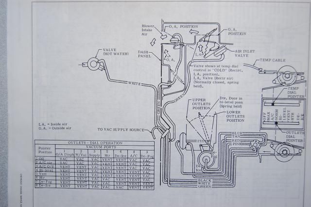
The A/C vacuum hose routing and connections are shown the the Options Section at the back of the AIM.
For A/C it's Section C60.
The vacuum hose routing and connections are shown on Sheets E1 through E5.
Here's an example of the information on one of the pages. (This is from the 71 AIM)
The vacuum and electrical parts of the A/C system are pretty complicated. I can't imagine working on it with out the AIM information.
Good Luck!
Regards,
Alan
05-30-2016, 05:47 PM
#4
Former Vendor
Member Since: Aug 2006
Location: Jeffersonville Indiana 812-288-7103
Posts: 76,656
Received 1,813 Likes
on
1,458 Posts
St. Jude Donor '08-'09-'10-'11-'12-'13-'14-'15
This is the correct one for the 1970 but I don't think it is any different than what Alan posted.


05-30-2016, 08:54 PM
#5
Drifting
Thread Starter
Thanks. The orange hose was one of the unknowns. Does the white stripe hose have a nipple that it attaches to prior to going to engine compartment?
I get to pull the heater core out again and make connections and route the hoses. How do I get to the plenum actuator to make sure the diaphragm and plastic/rubber is intact. I'm trying to make sure stuff is working before closing things up. It's both frustrating and rewarding to do this. Frustrating since I have nothing to compare it to and wasn't the one to take it apart. This also makes it interesting figuring out what fasteners go where, from the ones scattered across the floor of the passenger floor. It's rewarding that I'm doing it myself with some guidance from others.
I get to pull the heater core out again and make connections and route the hoses. How do I get to the plenum actuator to make sure the diaphragm and plastic/rubber is intact. I'm trying to make sure stuff is working before closing things up. It's both frustrating and rewarding to do this. Frustrating since I have nothing to compare it to and wasn't the one to take it apart. This also makes it interesting figuring out what fasteners go where, from the ones scattered across the floor of the passenger floor. It's rewarding that I'm doing it myself with some guidance from others.
05-30-2016, 10:11 PM
#6
Former Vendor
Member Since: Aug 2006
Location: Jeffersonville Indiana 812-288-7103
Posts: 76,656
Received 1,813 Likes
on
1,458 Posts
St. Jude Donor '08-'09-'10-'11-'12-'13-'14-'15
All of the actuator relays can be tested at the heater control switch with a migty vac.
The green hosed actuator is located inside the passenger side fender.
The brown and pink actuator is located behind the heater box and boy oh boy it's a bear to get to but again, test it from the vacuum control switch connector.
The red/blue hose actuator is the defrost one, it's easy to get to and when your get inside you'll see it first.
Keep in mind too.. it is very common for this plastic door retainer to break... and when it does it'll keep the plenum door from working properly.
The following users liked this post:
lizzzard (08-17-2017)
06-15-2016, 04:26 AM
#7

Hi all,
I'm troubleshooting my 1971 A/C corvette system.
Somebody knows what is the functionality of the A/C vacuum actuator, the one with the TAN and PINK hoses ?
If not connected it closes completely air from the heater and evaporator?
I found two hoses disconnected in my car.
One is orange and testing functionality is the recirc actuator. Connecting it the door doesn't work, maybe the actuator is not working. The flapper door is stuck in the middle, non closed, not opened.
The second hose is white, testing the functionality is the same as the one in TAN color in the diagram, port 8. Vacuum on position 1, 2 and 3. Vented all the other.
No fresh air comes out, the valve freezes, the compressor works, the blower motor run.
But with the blower motor at the maximum level, little air is coming out. And is not fresh.
Looks like all the door are closed before evaporator and heater and the blower just recirc small quantity of air present in the duct.
Thanks in advance
Last edited by abezze; 06-15-2016 at 08:23 AM.
06-15-2016, 08:56 AM
#8
Drifting
Thread Starter
I tested all the actuators with handheld vacuum tester. Some actuators ate three position and have a positive, neutral, and negative position. The blend door is the main one and is a PITA to get the the inside one if you have it mounted. I was able to test all actuators after taking loose the multi port connector from the switch assembly. I used a connector from the hand held tester to go inside each port. The white stripe is likely the heater control valve the mounts on the evaporator housing. The orange went to the passenger side footwell actuator (behind outside kick panel), and pink went to the inner blend door actuator (PITA to get to).
Doctor rebuild has diagrams on the links here http://www.docrebuild.com/dr-r-web/AC-VAC.HTML
Doctor rebuild has diagrams on the links here http://www.docrebuild.com/dr-r-web/AC-VAC.HTML
06-15-2016, 10:48 AM
#9
I tested all the actuators with handheld vacuum tester. Some actuators ate three position and have a positive, neutral, and negative position. The blend door is the main one and is a PITA to get the the inside one if you have it mounted. I was able to test all actuators after taking loose the multi port connector from the switch assembly. I used a connector from the hand held tester to go inside each port. The white stripe is likely the heater control valve the mounts on the evaporator housing. The orange went to the passenger side footwell actuator (behind outside kick panel), and pink went to the inner blend door actuator (PITA to get to).
Doctor rebuild has diagrams on the links here http://www.docrebuild.com/dr-r-web/AC-VAC.HTML
Doctor rebuild has diagrams on the links here http://www.docrebuild.com/dr-r-web/AC-VAC.HTML
I've got a pink hose that seems connected.
I know it's weird but I've got another white instead of tan that doesn't go outside and the functionality is like the one described as vacuum port 8 in AIM.
The green hose in AC vette should go outside to engine and then inside wiper comp. then into right fender as in this pic.

plenum valve A/C and flapper door inside fender
this evening I'll check if connected and working.
Could it be the reason why I got little air coming out ? I don't think so because my recirc valve is opened... air could come from inside to blower.
Last edited by abezze; 06-15-2016 at 11:02 AM.
06-16-2016, 09:24 AM
#10
Hi all,
yesterday i fixed the recirc door.
Inside the duct there was a 1/2 inch wrench, some canadian Canadian maple leaves also inside the actuator, and a lot of oxide.
Cleened and deoxidated, now working... a pleasant surprise... working again after so many year, oxide and dirt
And I found my problem is in the white hose not connected that shoud goes to the A/C valve.
The heater box doesn't open if the actuator is not in vacuum. No fresh air comes out from the evaporator.
It is done this way :
http://www.ebay.com/itm/1970-76-corv...5XGGSt&vxp=mtr
last year my mechanic substituted my heater core and maybe disconnected the hose without reconnecting it.
Last edited by abezze; 06-16-2016 at 09:48 AM.
08-17-2017, 03:20 PM
#11
hi dudes
i'm new in this forum and i know its an old thread.
but this hint is great!!! I'm looking exactly for this piece.
where can i find a new part? I tried ZIP, CC, Ecklers,... nothing.
I already sent a email to the willcox corvette team, but maybe someone in the forum may chime in.
i found this, but i dont know if it fits:
http://www.americanclassic.com/1971-...ctinfo/68-248/
any help is appreciated.
thanks!
milo
i'm new in this forum and i know its an old thread.
but this hint is great!!!
I'm looking exactly for this piece.where can i find a new part? I tried ZIP, CC, Ecklers,... nothing.
I already sent a email to the willcox corvette team, but maybe someone in the forum may chime in.
i found this, but i dont know if it fits:
http://www.americanclassic.com/1971-...ctinfo/68-248/
any help is appreciated.
thanks!
milo
All of the actuator relays can be tested at the heater control switch with a migty vac.
The green hosed actuator is located inside the passenger side fender.
The brown and pink actuator is located behind the heater box and boy oh boy it's a bear to get to but again, test it from the vacuum control switch connector.
The red/blue hose actuator is the defrost one, it's easy to get to and when your get inside you'll see it first.
Keep in mind too.. it is very common for this plastic door retainer to break... and when it does it'll keep the plenum door from working properly.