
ecs instal


 08-22-2015, 10:18 PM
#102
Race Director


Member Since: Dec 2010
Location: Atlanta, GA
Posts: 10,426
Received 1,261 Likes
on
1,056 Posts
2020 Corvette of the Year Finalist (performance mods)
C5 of Year Winner (performance mods) 2019

 08-23-2015, 06:58 AM
#103
Drifting

Thread Starter

what he did was all i wanted him to do. i want to do the rest myself. he was even a little pissed about the job, especially swearing at the a/c tensioner.
as mentioned, there is no way to get on the bridge with the filter. im going to try and cut it up and reweld it at an other angle, so the filter doesnt touch anything.
btw, we drilled out the a/c tensioner to 9.5 mm to make it fit the adjusting nut.
as mentioned, there is no way to get on the bridge with the filter. im going to try and cut it up and reweld it at an other angle, so the filter doesnt touch anything.
btw, we drilled out the a/c tensioner to 9.5 mm to make it fit the adjusting nut.
08-24-2015, 04:27 PM
#104
Drifting
Thread Starter
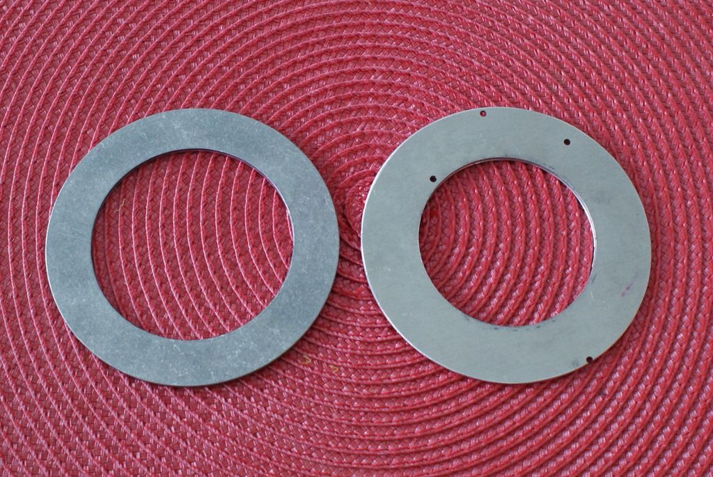
no idea how it was supposed to work, but i made these spacers to pull the intercooler grommets into the brackets:
now the intercoler sits tight in the brackets.

now the intercoler sits tight in the brackets.
08-24-2015, 04:49 PM
#105
Race Director
Member Since: May 2004
Location: Raleigh, NC
Posts: 16,664
Received 1,194 Likes
on
1,053 Posts
St. Jude Donor '15

I like it. Basically it just sits in there normally. The big washers/bolts stop it from coming out.. but it doesn't fit tight with the way ECS ships the kits.
08-25-2015, 03:18 PM
#106
Drifting
Thread Starter
today i installed the j-tube and lower rubber hoses and found the hoses are too long. did everybody have to shorten them? also it seems you have to cut up the front inner fender, the panel with the brake duct, to get the hose through. im asking, because i dont think i saw that mentioned anywhere.
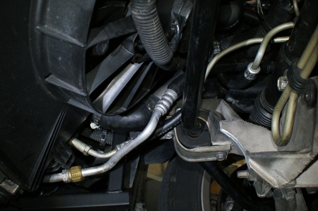
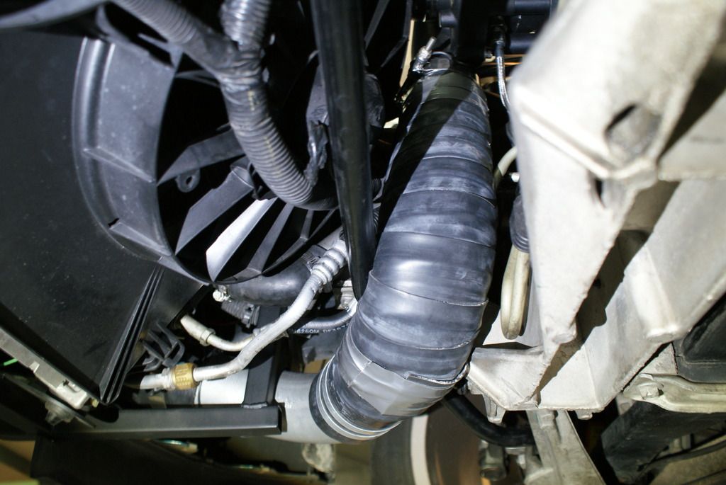
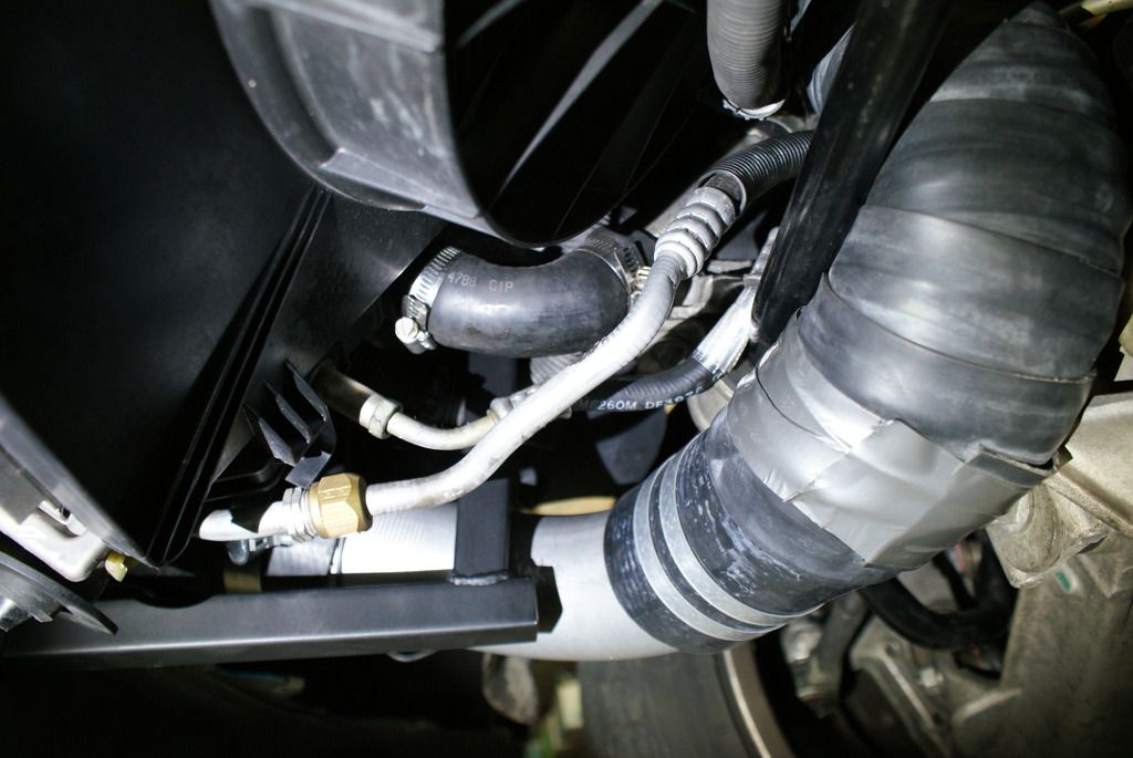
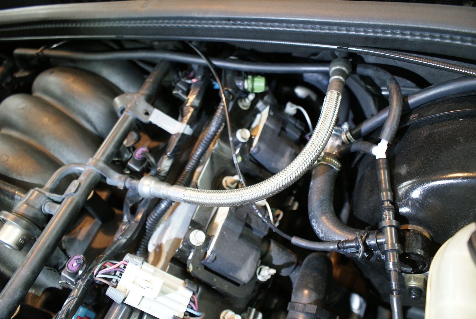
my a/c and trans cooler lines look like this:
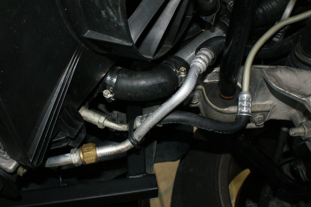
this will not work, the (lower) cooler line has to go over the sway bar. i just cant figure out what to do to get the rubber section straight and up.
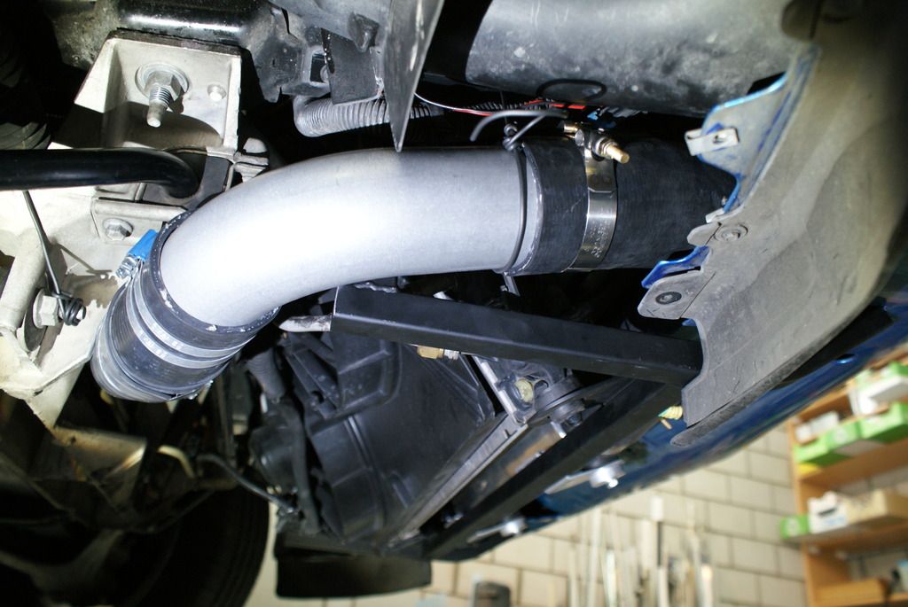
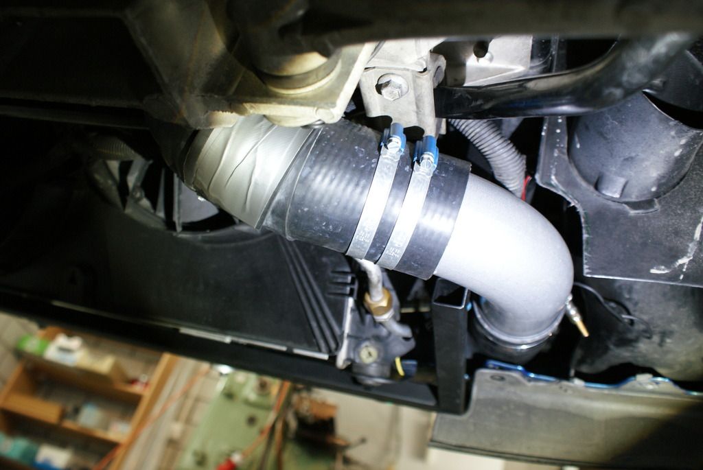
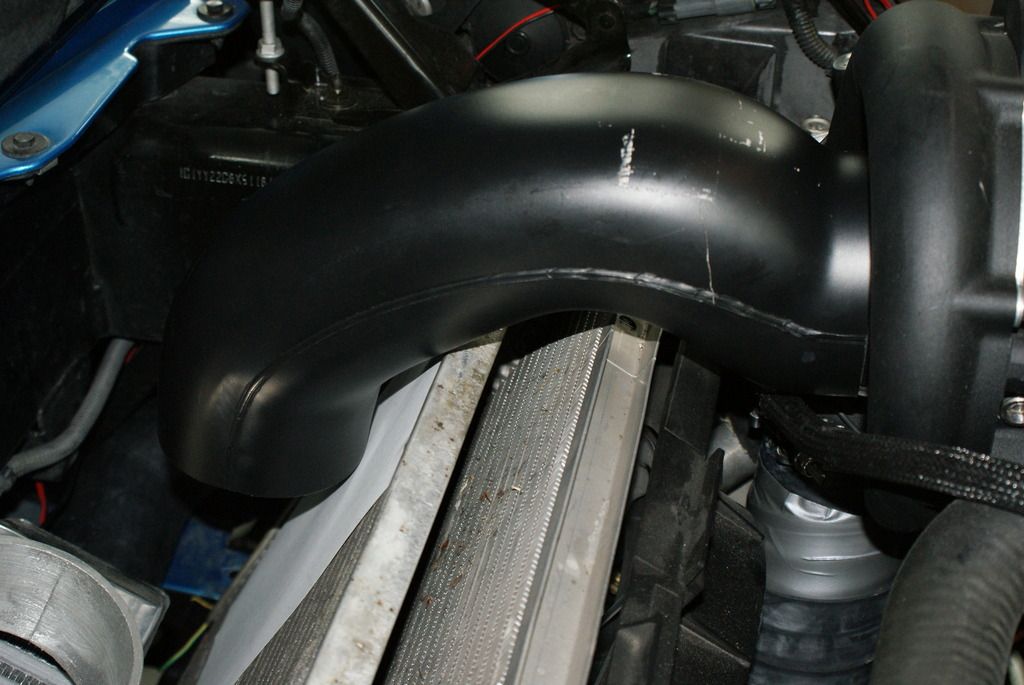
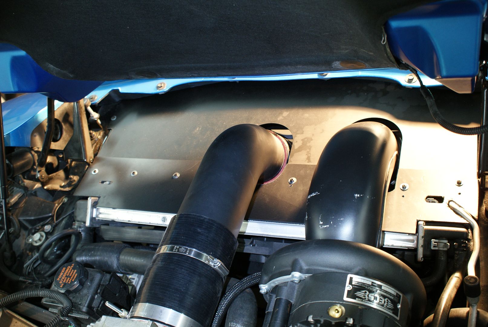
i also installed the charge pipe, now that the intercooler is in its final place:
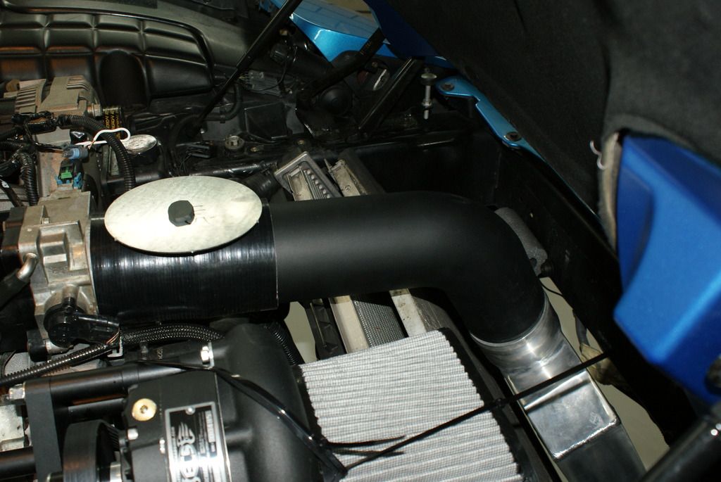
when i put a piece of clay on it and the round plate over the clay and close the hood the clay is 3-4 mm thick. with plate 4-5 mm. as the charge pipe should not touch the intercooler this becomes 2-3 mm. i suspect the hood liner will sag that much and rub on the pipe. they definitely should have made the pipe shorter with a slightly different angle. (i was measuring just before the elbow in front.)
my a/c and trans cooler lines look like this:


this will not work, the (lower) cooler line has to go over the sway bar. i just cant figure out what to do to get the rubber section straight and up.
i also installed the charge pipe, now that the intercooler is in its final place:

when i put a piece of clay on it and the round plate over the clay and close the hood the clay is 3-4 mm thick. with plate 4-5 mm. as the charge pipe should not touch the intercooler this becomes 2-3 mm. i suspect the hood liner will sag that much and rub on the pipe. they definitely should have made the pipe shorter with a slightly different angle. (i was measuring just before the elbow in front.)
Last edited by romandian; 08-25-2015 at 03:23 PM.
09-05-2015, 09:49 AM
#107
Drifting
Thread Starter
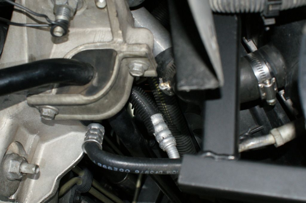
i disconected the upper cooler line and routed it around the a/c line, losened the lower cooler line and rotated the bend to point upwards and was then able to get both lines over the sway bar.
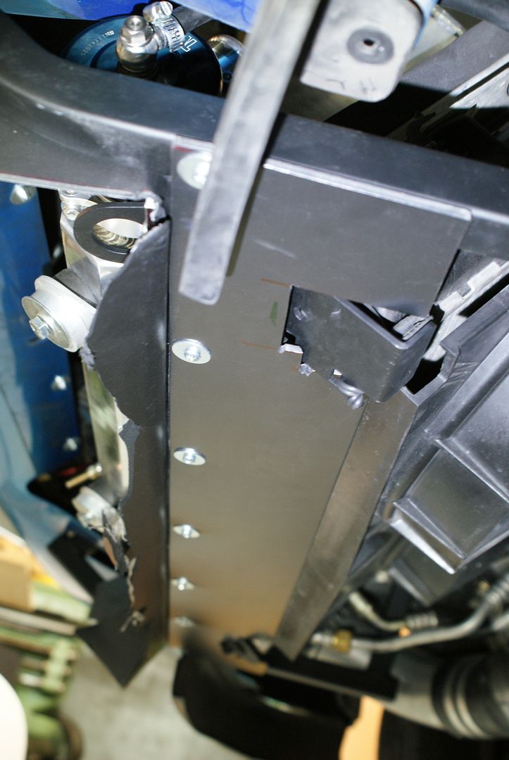
i intalled the j-pipe (long end goes to intercooler) and the hoses. it turns out its impossible to have the assembly above the horizontal panel (with louvers) like they seem to show in fig. 42 of instructions. as you see i already cut out the vertical panel for the hose, but its no good you have to completely cut off the left side of the horizontal panel for the hose to pass through.
i wraped the hose with a rubber band to protect it where it touches the subframe, roll bar and the hard lines.
i also made a smaller restrictor plate, 62 mm instead of 70.
here the bridge again. it pinches the paper and there is a 2 mm gap on the bottom at the inlet.
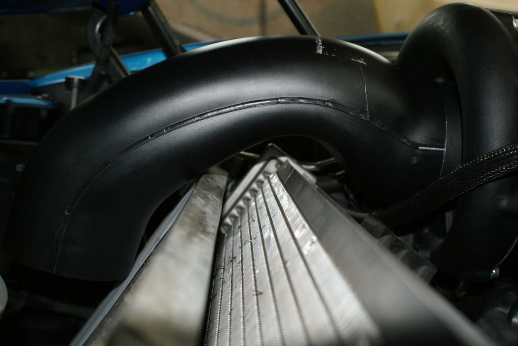
i managed to get it on with the filter using four hands and a lot of force. so now the filter is pressed against the condensor and will be rubbing as the engine moves. it sits crooked on the inlet and will probably come off on the first occasion. i dont like it at all.
also there is a 30 mm gap betwen the bridge and radiator (25 mm betwen condenser). the cross section could be much bigger there. why some guys flatten the top fins on the radiator beats me. due to differences between production years maybe?

i intalled the j-pipe (long end goes to intercooler) and the hoses. it turns out its impossible to have the assembly above the horizontal panel (with louvers) like they seem to show in fig. 42 of instructions. as you see i already cut out the vertical panel for the hose, but its no good you have to completely cut off the left side of the horizontal panel for the hose to pass through.


i wraped the hose with a rubber band to protect it where it touches the subframe, roll bar and the hard lines.


i also made a smaller restrictor plate, 62 mm instead of 70.

here the bridge again. it pinches the paper and there is a 2 mm gap on the bottom at the inlet.


i managed to get it on with the filter using four hands and a lot of force. so now the filter is pressed against the condensor and will be rubbing as the engine moves. it sits crooked on the inlet and will probably come off on the first occasion. i dont like it at all.
also there is a 30 mm gap betwen the bridge and radiator (25 mm betwen condenser). the cross section could be much bigger there. why some guys flatten the top fins on the radiator beats me. due to differences between production years maybe?
Last edited by romandian; 09-05-2015 at 10:29 AM.
09-05-2015, 10:55 AM
#108
Race Director
Member Since: Dec 2010
Location: Atlanta, GA
Posts: 10,426
Received 1,261 Likes
on
1,056 Posts
2020 Corvette of the Year Finalist (performance mods)
C5 of Year Winner (performance mods) 2019
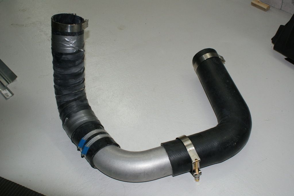
the long coupler you have on the charge pipe connecting it to the throttle body is in the wrong place, that coupler needs to go where the intercooler connects to the charge pipe... why not just ditch the plastic dongle and make your own 4" inlet?... you can get a 4" piece if stainless pipe for cheap and cut it down to the proper size and be done... that's what I had to do with mine, I didn't have a plastic dongle like you do but the inlet they provided me was equally as bad... I wasn't impressed with the blower to intercooler charge piping myself, it's just a couple of generic rubber 90 degree hoses that need to be trimmed to fit
09-20-2015, 03:19 PM
#109
Drifting
Thread Starter
in my case the charge pipe toutches the intercooler and there is 3" between pipe and tb. i saw the longer coupler down by the intercooler in other builds as you say, no idea how come. in your "before picts" the blower inlet hose seems to be at an angle and go over the rad. how did you do that?
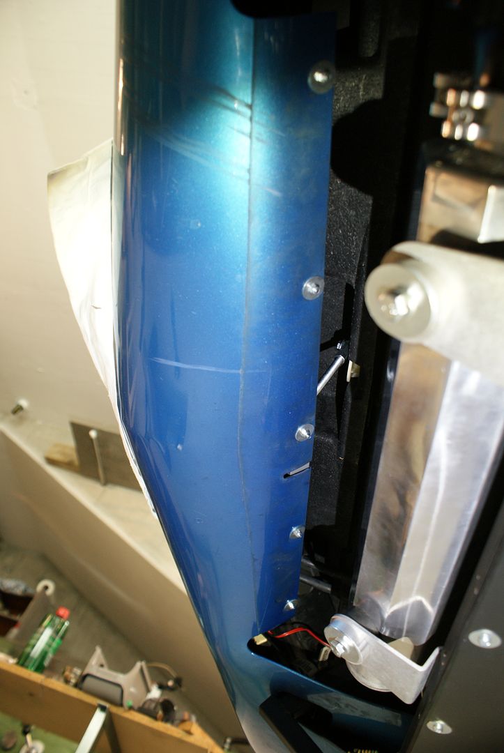
i didnt feel like cutting up the upper radiator mount, so my solution looks like this:
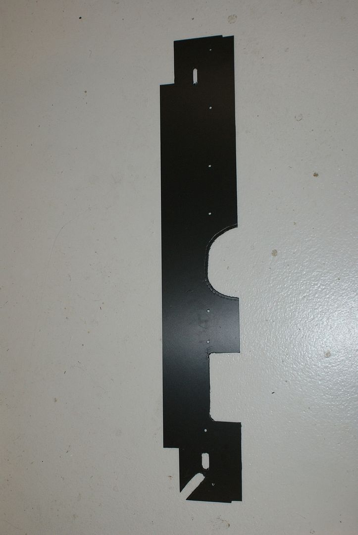
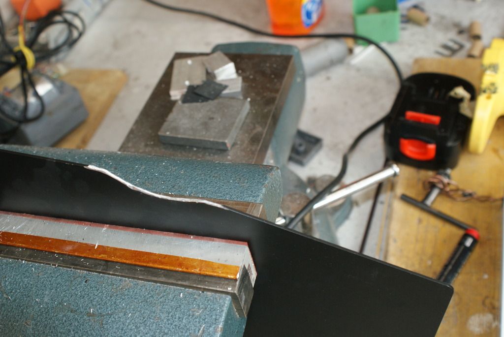
i also trimmed the original plate to go in easier:
this is the block off plate between intercooler and rad:
you can also see the remains of an experimental spoiler that scooped forward and was too low (5 cm above ground).
this is the original iat sensor:
i also stabilized and pulled up this plastic part, to enlarge the air entry a bit and to make sure it doesnt do anything funny during high speed runs.
finally i got a smaller horn, bacause i couldn figure out how i was supposed to install the original one.
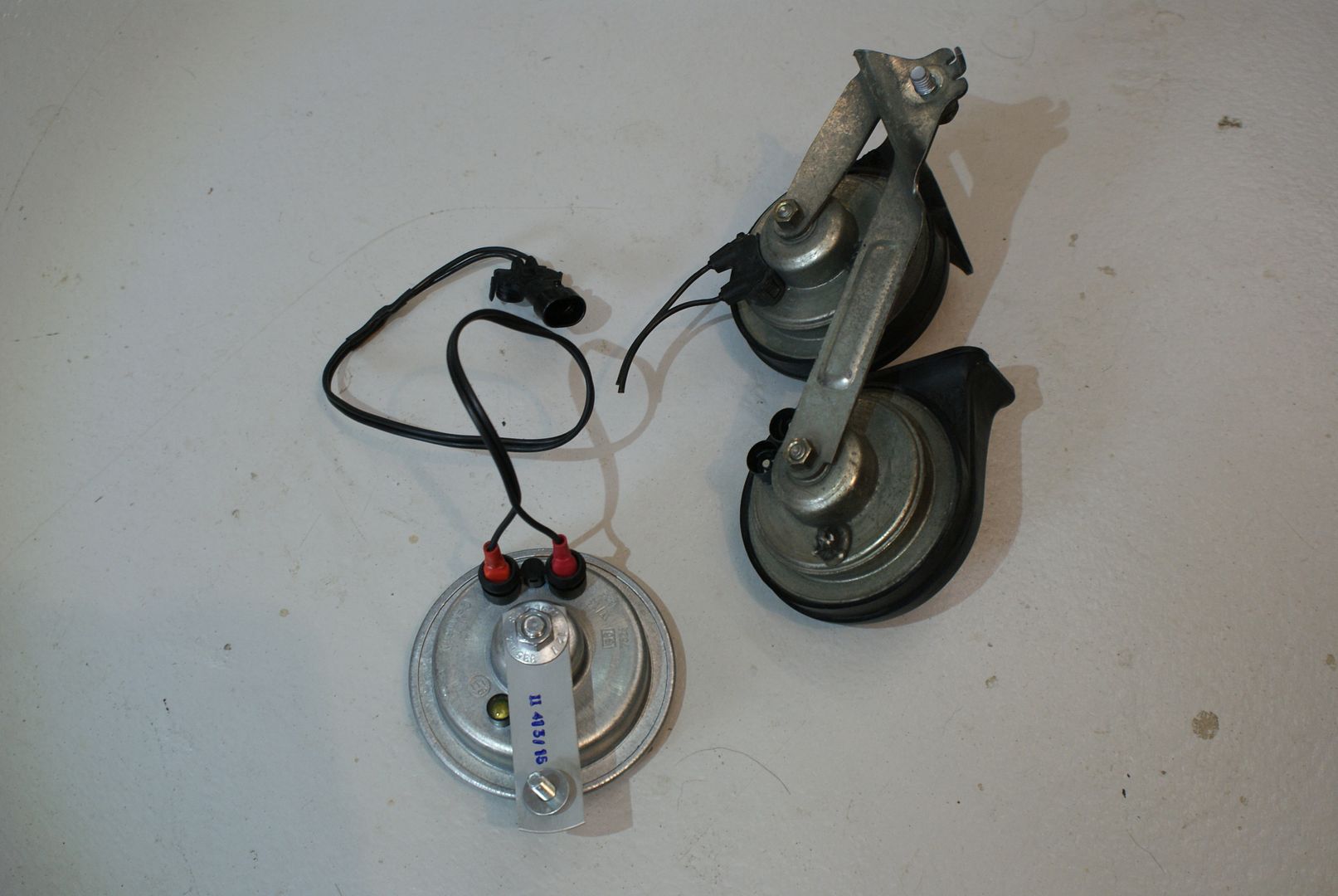
i put it above the passanger fog light like this.
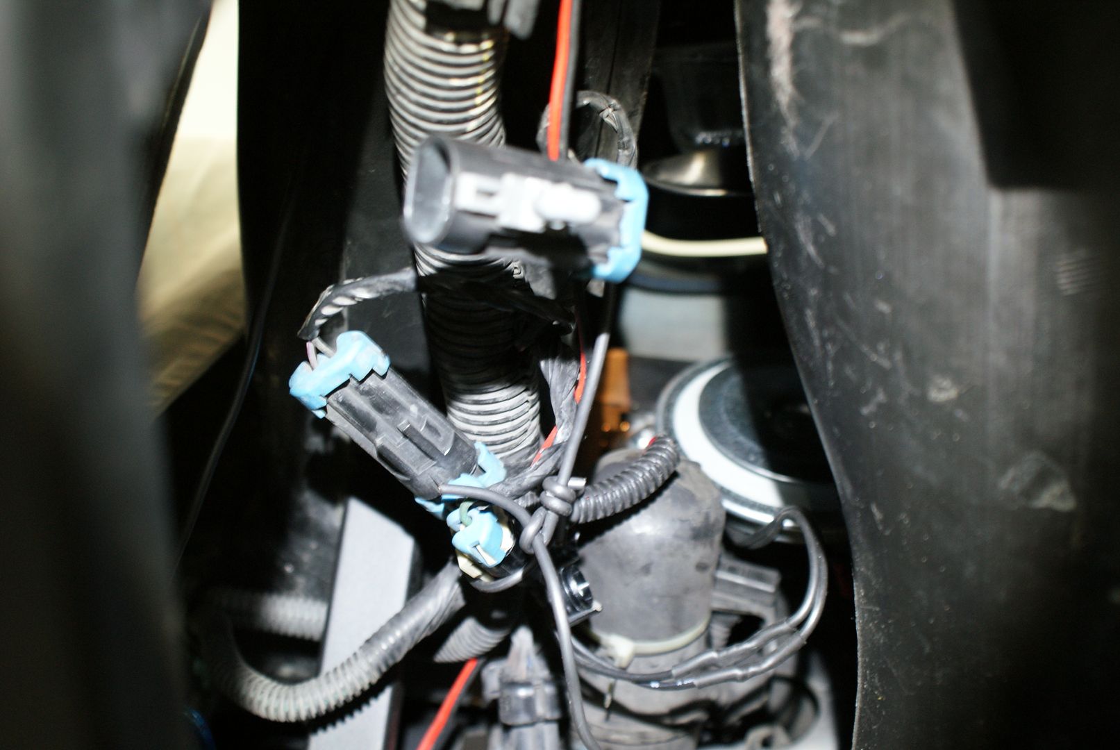
would anybody know what the loose connector is for? i suspect it was in there like that before, just trying to make sure.
i didnt feel like cutting up the upper radiator mount, so my solution looks like this:


i also trimmed the original plate to go in easier:

this is the block off plate between intercooler and rad:

you can also see the remains of an experimental spoiler that scooped forward and was too low (5 cm above ground).
this is the original iat sensor:


i also stabilized and pulled up this plastic part, to enlarge the air entry a bit and to make sure it doesnt do anything funny during high speed runs.

finally i got a smaller horn, bacause i couldn figure out how i was supposed to install the original one.

i put it above the passanger fog light like this.

would anybody know what the loose connector is for? i suspect it was in there like that before, just trying to make sure.
09-20-2015, 03:45 PM
#110
Race Director
Member Since: Dec 2010
Location: Atlanta, GA
Posts: 10,426
Received 1,261 Likes
on
1,056 Posts
2020 Corvette of the Year Finalist (performance mods)
C5 of Year Winner (performance mods) 2019
in my case the charge pipe toutches the intercooler and there is 3" between pipe and tb. i saw the longer coupler down by the intercooler in other builds as you say, no idea how come. in your "before picts" the blower inlet hose seems to be at an angle and go over the rad. how did you do that?
10-05-2015, 05:47 AM
#111
Drifting
Thread Starter
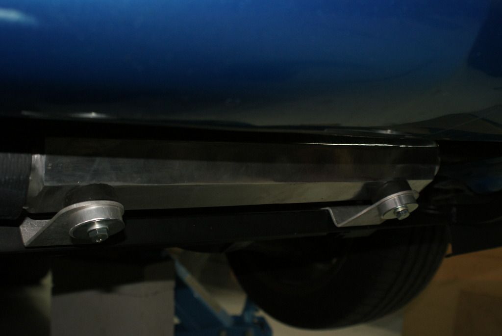
i ordered some 90 x 6 mm nr/sbr rubber and the current spoiler looks like this:
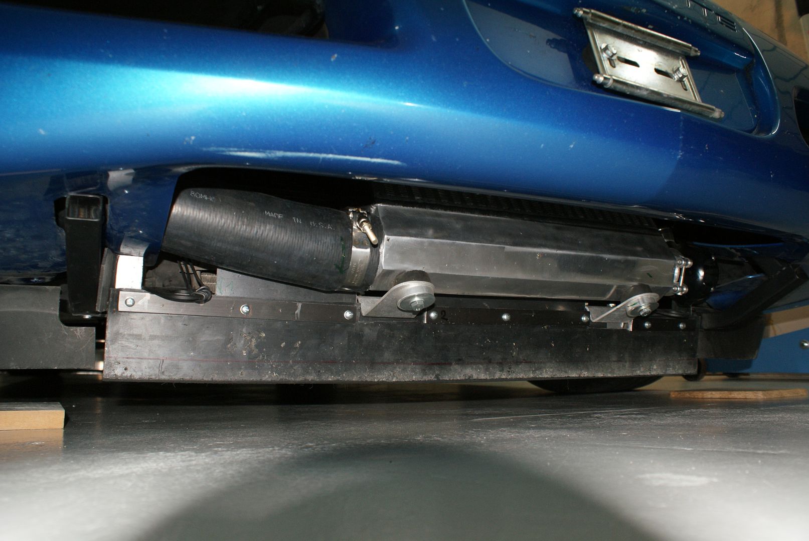
the stuff is supposed to be abrasion resistant, will see. its 5 cm above ground, like the scoop was, but doesnt touch the road on bumps because its closer to the wheels. the side rubber pieces are 7 cm above ground. in case anybody wonders, the original radator cradle was 22 cm below the main frame (at the front bolts) as opposed to 24 cm fpr the ecs cradle, which puts it 11 cm above ground. the original spoiler was 8 cm above ground or 27 cm below the main frame rails.
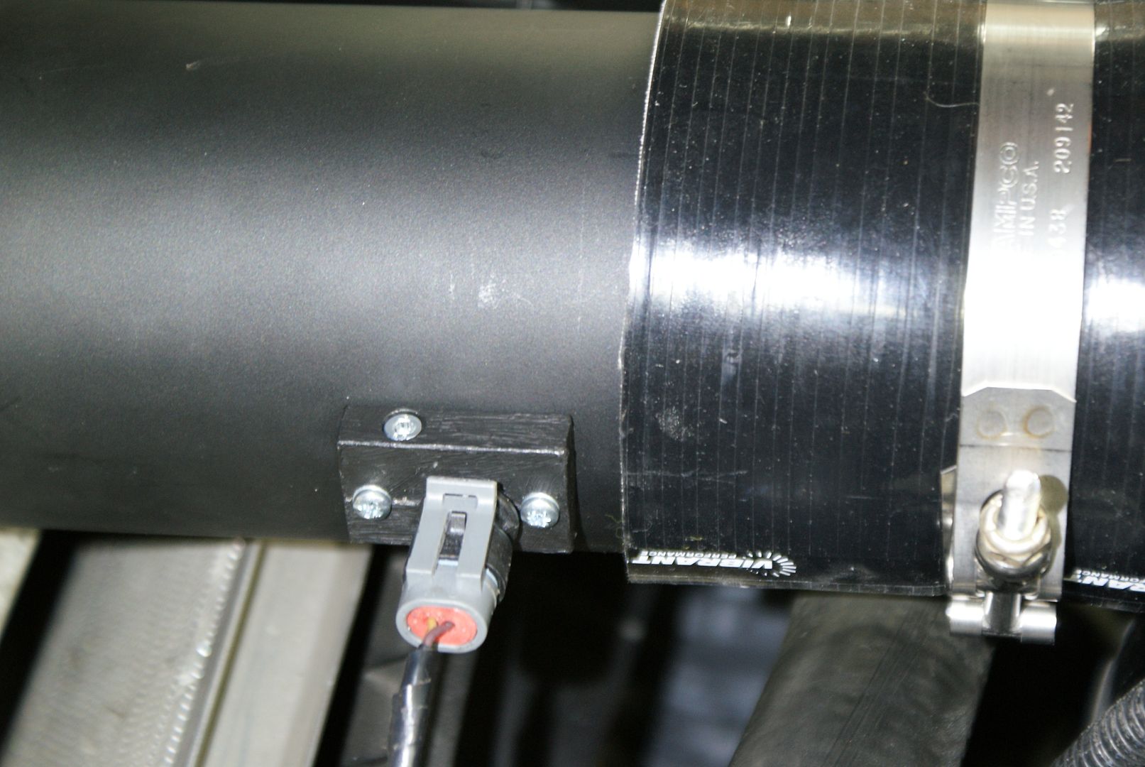
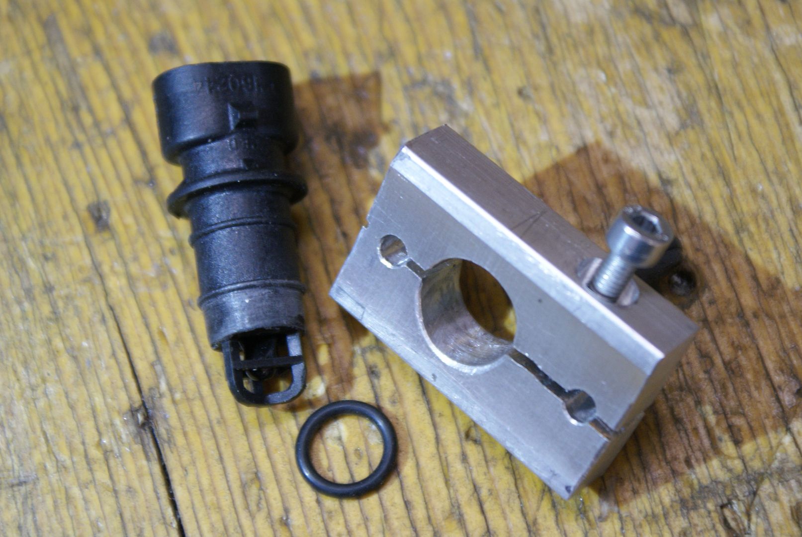
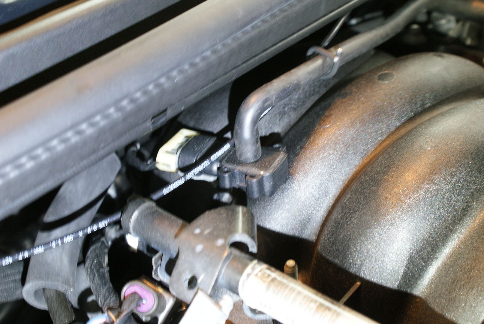
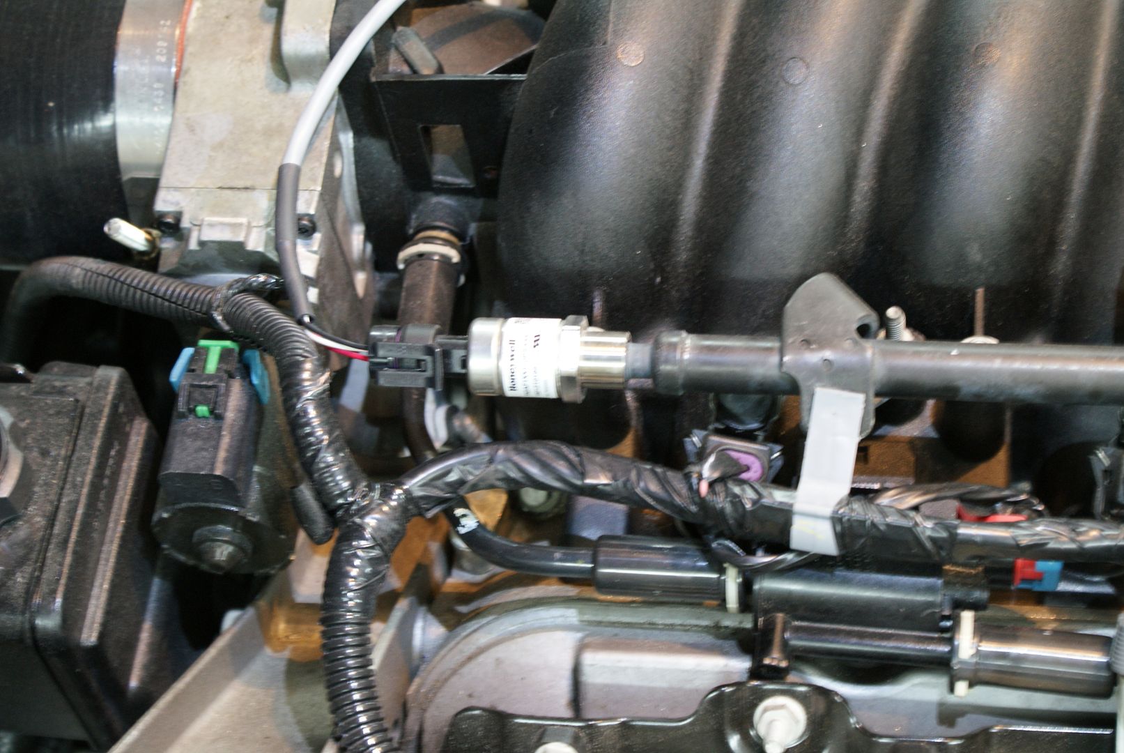
i didnt feel like messing with the original map sensor and possibly breaking something back there, so a new (12615136) sensor is installed like this:
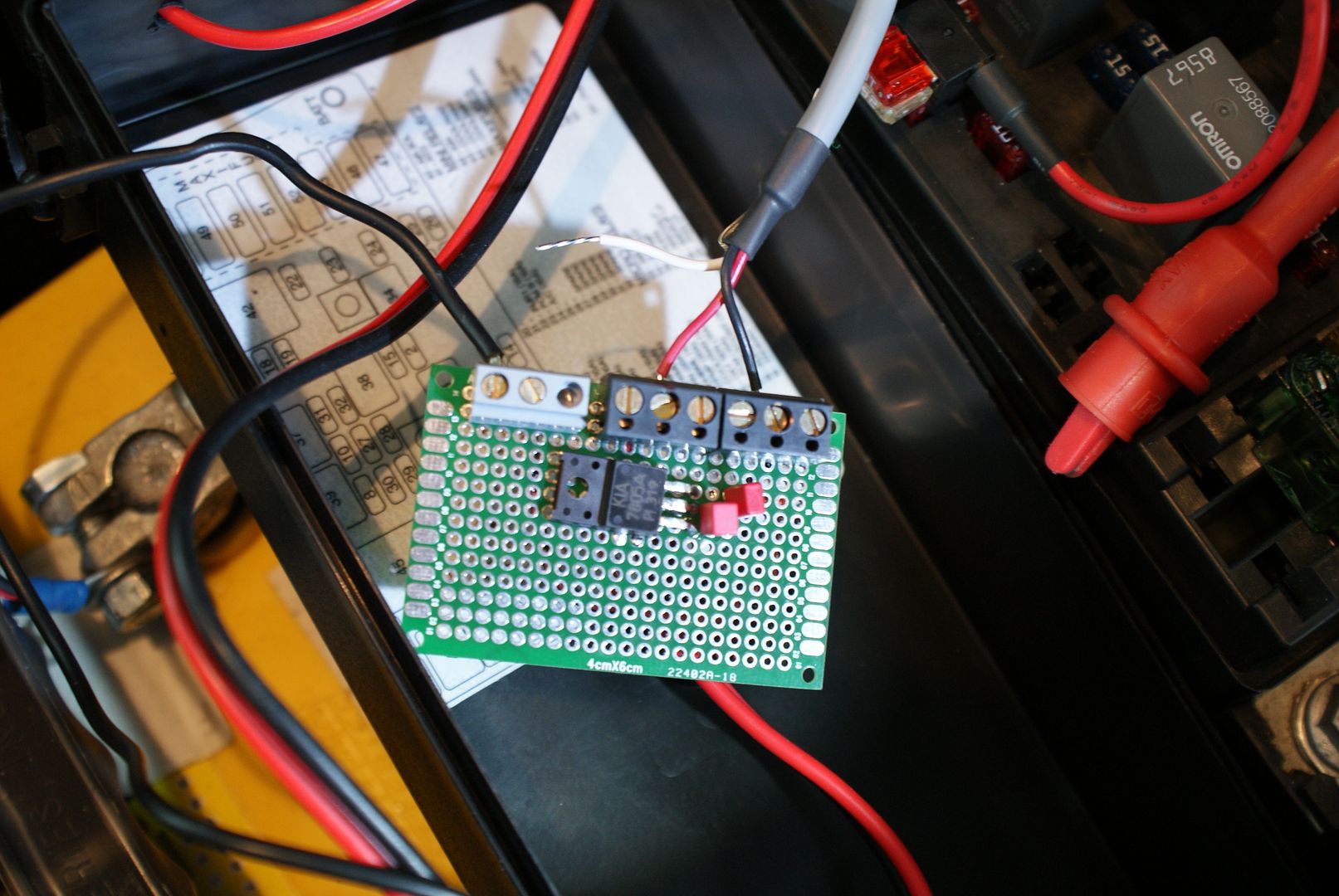
fp sensor and a little board i made for the switched 12v and 5v power supplies:

the stuff is supposed to be abrasion resistant, will see. its 5 cm above ground, like the scoop was, but doesnt touch the road on bumps because its closer to the wheels. the side rubber pieces are 7 cm above ground. in case anybody wonders, the original radator cradle was 22 cm below the main frame (at the front bolts) as opposed to 24 cm fpr the ecs cradle, which puts it 11 cm above ground. the original spoiler was 8 cm above ground or 27 cm below the main frame rails.
i didnt feel like messing with the original map sensor and possibly breaking something back there, so a new (12615136) sensor is installed like this:


fp sensor and a little board i made for the switched 12v and 5v power supplies:


 10-05-2015, 03:45 PM
#112
Drifting
Thread Starter

this is the ecotrons wideband. (http://www.ecotrons.com/products/wid...ler-alm-gauge/)
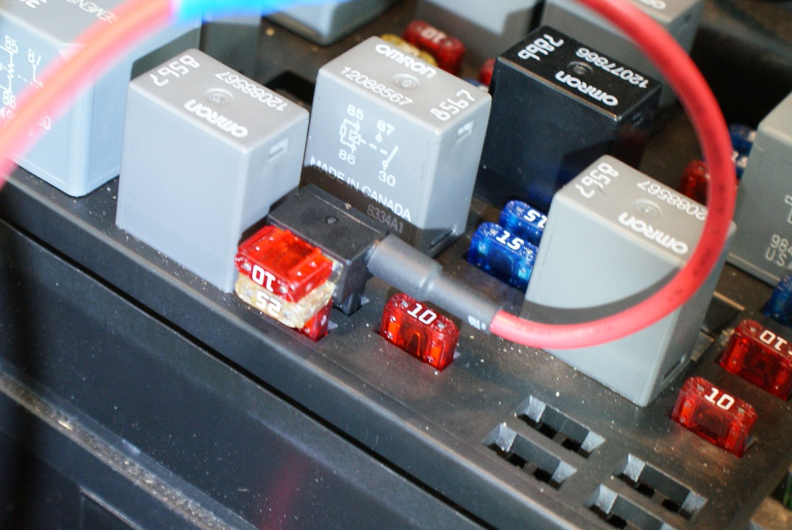
i still have to really study the manuals, but it has a rpm input and does logging on its own. i like the round conectors, they fit through a 16 mm hole. i drilled above and to the right of the fuse box:

this is where you come out behind the battery:

i was afraid of this step, but was done in a few minutes. first i thought the sensor cable might be too short. its not, but the connetor is in the wrong place, just at the cat:

the more you wrap it the lower it gets. not a permanent solution like this. its the gauge cable thats too short, i couldnt route it around the dash although the box is inside. all in all the kit is well made, all silicone or teflon wires because all the cables are very flexible. well see how it works.

thats what the cockpit looks like now. the vacum/boost gauge is just to logg a few part throtle passes and will be replaced by this:

i spent quite some time sourcing a 0-15 psi gauge. this is the only one i found, no 0-1 bar gauges out there either. its a vdo apparently for the u.s. market only, so i got it from egauges (150-051). these gauges are for tuning only. in the end ill have some digital solution or get rid of them completely, but only when i know the tune is bulletproof.
i have the lingenfelter pump in there now. fp is 66 psi at idle and falls to 52 psi at 76% duty cycle with the 60 lbs injectors, loosing 8% of flow. i dont like that.
i put in this stuff also:

so the car is ready for tuning.
would anybody share what injector data works with the ecs injectors ("siemens" deka 60 lbs, 107-961)? flow rates, small pulse adjust and voltage offsets?
iv had the engine up to 0.65 bars at 5200 rpm so far. without restrictor that is. it pulls 0.55 g in second gear as opposed to 0.34 g stock.

these came on friday. what i find weird, however, is that the car doesnt loose traction at all in second gear, it stays well planted even on an irregular road. on old runflats that is. how much boost do you need to spin the tires?
Last edited by romandian; 10-05-2015 at 03:49 PM.
10-05-2015, 06:41 PM
#113
Premium Supporting Vendor
Member Since: Oct 2004
Location: Providing the most proven supercharger kits for your C5/6/7 609-752-0321
Posts: 23,316
Received 1,086 Likes
on
657 Posts
Shoot me an email and I'll send you the injector data. Didn't I send you a start up file already though?
10-06-2015, 12:07 PM
#114
Drifting
Thread Starter
yes doug, you did and it was a tremendous help, because i didnt have to mess around with installing a custom operating system. i just flashed in your file and the car started and drove without any problems (big surprise). however i see that different tunes have very different injector data in them, so i would like to compare and check my own thinking on this.
btw, the problem with the engine kind of bogging in gear i mentioned earlier has gone away after a short while. it started to idle very well at 650 rpm after about 200 miles, apparently there is some breaking in of the blower.
in case anybody wonders, the blower will produce positive pressure at idle, 1.1 bars at 2800 rpm and then 1.15@2800, 1.20@3200, 1.30@3800, 1.40@4400 and 1.65@5300 without restrictor. with my small restrictor it lags by 0.05 bars @3600, 0.1@4000, 0.2@5200 and tops out at 1.5 bars@6000.
Last edited by romandian; 10-06-2015 at 01:05 PM.
10-06-2015, 01:03 PM
#115
Premium Supporting Vendor
Member Since: Oct 2004
Location: Providing the most proven supercharger kits for your C5/6/7 609-752-0321
Posts: 23,316
Received 1,086 Likes
on
657 Posts
yes doug, you did and it was a tremendous help, because i didnt have to mess around with installing a custom operating system. i just flashed in your file and the car started and drove without any problems (big surprise). however i see that different tunes have very different injector data in them, so i would like to compare and check my own thinking on this.
btw, the problem with the engine kind of bogging in gear i mentioned earlier has gone away after a short while. it started to idle very well at 650 rpm after about 200 miles, apparently there is some breaking in of the blower.
in case anybody wonders, the blower will produce positive pressure at idle, 1.1 bars at 2800 rpm and then 1.15@2800, 1.20@3200, 1.30@3800, 1.40@4400 and 1.65@5300 without restrictor. with my small restrictor it lags by 0.05 bars @3600, 0.1@4000, 0.2@5200 and top out at 1.5 bars@6000.
It shouldn't produce positive pressure at idle, the BOV would be open relieving any pressure.
10-06-2015, 01:11 PM
#116
Drifting
Thread Starter
thats what i meant. valve is open and blowing strong. dont point the outlet down, because on a dirty road when you stop youll find yourself in a cloud of dust and the engine compartment will be full of it.
Last edited by romandian; 10-06-2015 at 01:16 PM.
10-08-2015, 10:12 AM
#117
Drifting
Thread Starter
did you get my mail, doug?
the bow can actually be blowing of when in boost. this seemed strange but on second thought makes sence. what happens when making a pass at around 100 kpa, however, is no good: the bow starts opening and closing at about 1 hz. on the street you will not often experience this, but on a road course it will be a problem. is this normal? what can be done? i was thinking an adjustable restrictor in the bow vacuum line maybe.
now some thoughts on the intercooler. the max. rise in temperature has been 9�c on a very long pass in second gear. (sometimes the temp. even drops when in boost.) now lets assume you start a pass at 120 kpa and finisch at 170 kpa. compressor efficiency assumed at 65%. 1.2^0.283= 1.05 and 1.7^0.283=1.16. so temps rise 5 and 16% at 100% adiabatic. 5/0.65=7.7 and 16/0.65=24.6. so at 293�k temps rise 293x0.077=23�c and 293x0.24.6=72�c. so the intercooler makes 5� out of 50� on a typical pass, pretty good i figure. of course this is not steady state. what happens when it gets fed 100�c air for a couple of minutes i will find out later.
10-08-2015, 10:16 AM
#118
Race Director
Member Since: May 2004
Location: Raleigh, NC
Posts: 16,664
Received 1,194 Likes
on
1,053 Posts
St. Jude Donor '15
Something doesn't sound right IMO
The bypass valve should be OPEN when NOT in boost. Just going down the highway (autobhan? ) it should be open and bypassing a good bit of air..
Around -2 psi on the "boost" scale, it will close so then you can build boost.. and it should stay closed from then on
The bypass valve should be OPEN when NOT in boost. Just going down the highway (autobhan?
) it should be open and bypassing a good bit of air..Around -2 psi on the "boost" scale, it will close so then you can build boost.. and it should stay closed from then on
10-08-2015, 01:41 PM
#119
Drifting
Thread Starter
well, mine is still open at 2 psi boost positive. at part throtle. i dont know, maybe its sticking a little? ill have to check it out some more i think.
10-08-2015, 02:45 PM
#120
Race Director
Member Since: May 2004
Location: Raleigh, NC
Posts: 16,664
Received 1,194 Likes
on
1,053 Posts
St. Jude Donor '15
Yeah, something isn't right.. make sure there aren't any vacuum leaks is the obvious first step.
If you have a mityvac you can connect the bypass valve vacuum hose to that and open/closed it with the mityvac and make sure it stays where it is supposed to (or find the leak if there is one)
If you have a mityvac you can connect the bypass valve vacuum hose to that and open/closed it with the mityvac and make sure it stays where it is supposed to (or find the leak if there is one)