
I got a cheap Corvette, or did I?
 06-30-2015, 08:09 PM
#81
Advanced

Thread Starter

The relay that was found behind the BCM is not likely the blower motor relay. See my post # 82 in BOLD BLUE inside the QUOTE of cody's previous post for what I suspect the relay to actually be.
Cody if you can get the color of ALL the wires in that relay match them to my post 82.
Cody if you can get the color of ALL the wires in that relay match them to my post 82.
I have stared at that schematic so long it is making sense. If there is power at the resistor then that relay has to be good right? I mean, we have determined that the power is coming from fuses 18/51 and the relay looks like it relays that power and grounds to g202. I am hoping the actual control unit is not bad b/c that means pulling it and sending it in for repair. It is no longer available from GM. Yuck!
I am at a loss. I haven't the time, because I am a hostage at work, or the knowledge / experience, or the patience for this. I just need to live with the fact that i have 2 50 air. 2 windows down 50 miles per hour. and who wants to drive a vette in the winter?
 06-30-2015, 09:04 PM
#82
Advanced
Thread Starter
Fun Fact!!! I am tinkering with the headlight and bump the left front chassis ground in the engine bay and "ding, ding, ding'.....turns out I DO have a door open dinger ha ha. I checked that ground the other day when I noticed it had been chopped off and ran direct to the post. I guess the wires are not as tight in the copper bracket as I thought. Give it a jiggle and ding.....ding.....ding. ha ha ha ha ha ha ha ha ha ha
 07-01-2015, 03:55 AM
#83
Drifting


The relay that was found behind the BCM is not likely the blower motor relay. See my post # 82 in BOLD BLUE inside the QUOTE of cody's previous post for what I suspect the relay to actually be.
Cody if you can get the color of ALL the wires in that relay match them to my post 82.
Cody if you can get the color of ALL the wires in that relay match them to my post 82.
The high speed fan control relay, if it is its own piece of equipment, should have orange, red, black, and purple wires.
07-01-2015, 11:27 AM
#84
Le Mans Master


What a great thread, yet another on this splendid forum. I'm sorry to be offtopic but this... is... what... Corvette is all about!! A community of incredibly enthousiastic and willing-to-help people who are also very knowledgable.
Going further offtopic... owning an American car in Europe can be a bit of a frightening thought / enterprise as regards costs or parts + shipment and also regarding (specialized) service... but this forum in particular never fails to do away with any of such fears. So many solutions and if one isn't there yet it's given almost instantly upon asking. Major compliments!!
End of offtopic, back to lurking this thread and learning.
Mr. Sam
07-03-2015, 09:10 PM
#85

Originally Posted by csmoore88
I have figured out what the black cube is behind the BCM. It is the "High Speed Fan Control Relay" It is loose behind the BCM and has several wires running into a wire plug, this plug is pictured in a previous post and has an orange wire coming out clipped about 5 inches out.
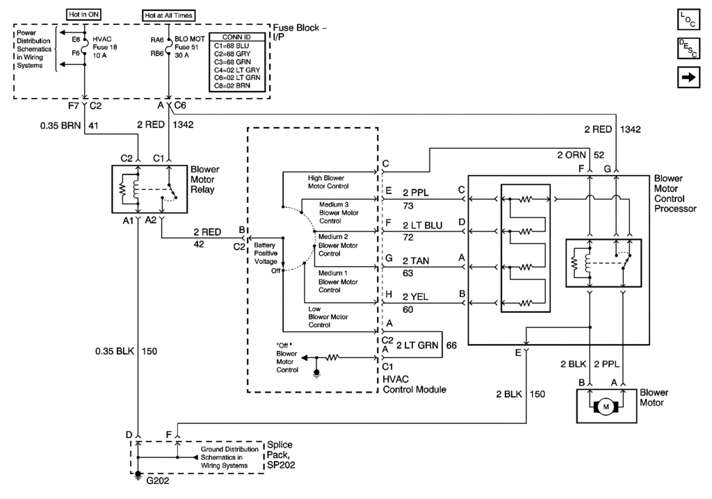
If I read Bill's wiring diagram correctly, the high speed fan control relay is supposed to be inside the blower motor control processor. However Cody mentions it sitting loose behind the BCM, apparently outside the blower motor control processor.
That relay box isn't just responsible for the 'high' setting of the blower, it also facilitates the other blower speed options. At 'high' setting, the coil in the relay will pull a switch so that current flows directly from the fuse block to the blower motor, through the red wire. At any other setting, the coil isn't energized and the current flows through one or more of the resistors in the blower motor control processor. Summarized, the relay box is always in use when the blower is not in 'off' position.
Apparently in the past someone has pulled that relay box out of the blower motor control processor. Probably not because it was working fine. I reckon you're not the first to try to tackle this problem.
And apparently someone found it necessary to replace some wires, because:
Originally Posted by 8VETTE7
(diagram shows BLK and PPL but the wires on the replacement Blower Motor Control Processor were BLK and RED.)
Regarding your processors, perhaps both of them are bad...
Cody,
1. Where did you get the 'new' blower motor control processor? Was it a spare part, an 'extra' to the car when you bought it? And what did the previous owner tell you about it? Did he reckon it'd be okay? Considering the fact that someone apparently already did some work on it, it could be that this new processor wasn't the answer the previous owner or his mechanic was looking for.
2. I assume that this uninstalled processor still has its 'high speed' relay inside?
3. Have you performed tests on both 'old' and 'new' relays?
4. Have you also checked the diameter of the new wires? Does it have size 2 as specified in the wiring diagram?
Last edited by Munckhof; 07-03-2015 at 09:32 PM. Reason: Clearer questions
07-03-2015, 09:31 PM
#86
Advanced
Thread Starter
It seems so.
If I read Bill's wiring diagram correctly, the high speed fan control relay is supposed to be inside the blower motor control processor. However Cody mentions it sitting loose behind the BCM, apparently outside the blower motor control processor.
That relay box isn't just responsible for the 'high' setting of the blower, it also facilitates the other blower speed options. At 'high' setting, the coil in the relay will pull a switch so that current flows directly from the fuse block to the blower motor, through the red wire. At any other setting, the coil isn't energized and the current flows through one or more of the resistors in the blower motor control processor. Summarized, the relay box is always in use when the blower is not in 'off' position.
Apparently in the past someone has pulled that relay box out of the blower motor control processor. Probably not because it was working fine. I reckon you're not the first to try to tackle this problem.
And apparently someone found it necessary to replace some wires, because:
and I recall having read somewhere in this thread that Cody also found some other wires to have unexpected coloring.
Perhaps both processors are bad... Cody,
1. where did you get the 'new' blower motor control processor?
2. I assume that this uninstalled processor still has its 'high speed' relay inside?
3. Have you performed tests on both 'old' and 'new' relays?
4. Have you also checked the diameter of the new wires? Does it have size 2 as specified in the wiring diagram?
I apologize to all of the interested parties and those who have offered to help. I truly do work 11-15 hours a day and, other than Sunday, I really have NO time for my car. It is ripping me apart at a molecular level because I have made (we have made) such progress that ALL I WANT IN THE WORLD is to bring this thing home and fix the last obstacle. But the fact remains that I leave at 5:45-6 a.m. and do not return home until 8:30 ++++. I hope no one thinks I gave up. I am just waiting for Sunday when I can attack it again.
I trusted the dealership to put my headlight gear in b/c I was covered up with work. $150!!!!!!!!!! just for a brass gear replacent. Well, they will not do another repair on my C5. I am on my own in a town that I just moved to and know not a soul. Corvette forum has saved my @$$ and I value you all!!!
07-03-2015, 09:51 PM
#87
I discovered the high speed fan control relay by searching for HVAC parts on Amazon looking for this specific component. It doesn't look like it was ever part of any other part and has its own individual part number from GM. Maybe I am just crazy(i.e. stupid) but it is not a part I would expect to have been pulled from any other component. Thoughts guys?
The relay having its individual part number makes sense because it's a separate part within the BMCP. In case of a failing relay, GM mechanics would (perhaps more cheaply) replace that relay rather than the whole BMCP.
ALL I WANT IN THE WORLD is to bring this thing home and fix the last obstacle.
As long as the car runs that's great. The more functions that work, the more bonus

I hope no one thinks I gave up.
07-03-2015, 11:25 PM
#88
Drifting
I'm not sure that the 'blower motor control processor' is a discrete piece of equipment in this schematic. I think it may be a term that GM is using to refer to the resistor block and the relay as a unit, but that the components are separate.
The only justification I have for this is that usually on these schematics, a single piece of equipment is indicated by a dashed line. See above at the fuse block, the 'HVAC Control Module,' the ground splice pack, etc. Those are all individual components and they all have dashed lines.
The BMCP is a solid line, and it certainly seems that at least in Cody's case, the parts are separate from each other. Hopefully Cody can get us a good picture of the relay and the broken wires at some point so we can see what's what.
07-04-2015, 07:40 AM
#89
Le Mans Master
The FSM shows the Processor has a single connector with 7 pins that match ALL the inputs. It should also have a Purple and Black pigtail out of it with a connector for the motor. That is all.
Therefore, based on the FSM, the processor high speed relay is INSIDE the Processor with the resistor, not external.
Figuring out why the bower motor does not run should a few minutes job. This is as simple a circuit as you can find in the C5. I wish I was closer I would just come over and do it.
OP, I would be glad to walk you through the diagnostics over the phone. You have my number and I have yours.
I can tell you exactly where to put the Red probe and where to put the Black probe.
There should be only about 6 individual checks to figure out where the problem is.
As I understand there has yet to be a test to see if the motor is good. A simple resistance check might just show it is bad (open circuit in the motor).
07-04-2015, 11:00 AM
#90
Le Mans Master
Thanks Chuck, good input. I will focus on that. It should be easy to find out where the voltage is dropping. We need to get full battery voltage to the motor connector Purple wire for high speed and then we'll worry about if the motor is bad.
I left him a message earlier to tell him I was available any time he was.
When you two did that was he testing voltage at the Purple wire using the Black wire at the connector as his ground or a separate known ground point?
I left him a message earlier to tell him I was available any time he was.
When you two did that was he testing voltage at the Purple wire using the Black wire at the connector as his ground or a separate known ground point?
07-04-2015, 12:00 PM
#91
Advanced
Thread Starter
I believe it was just across the two pins in the connector to the fan. He has a replacement resistor pack which has a black and a red wire and no longer the OEM purple color wire. I call it a resistor pack but the correct (GM)name is Blower Motor Control Processor.
We did verify battery voltage to both the red wire and orange wire ( fan in HIGH) (top of the diagram Bill C provided) by using another KNOWN ground. Don't think we did a known ground for the fan 2 wire connector. Also will mention that Cody did service ground 202 because his passenger window was not working and that ground was the cause. Could be one of the splice packs on that ground is still problematic....
We did verify battery voltage to both the red wire and orange wire ( fan in HIGH) (top of the diagram Bill C provided) by using another KNOWN ground. Don't think we did a known ground for the fan 2 wire connector. Also will mention that Cody did service ground 202 because his passenger window was not working and that ground was the cause. Could be one of the splice packs on that ground is still problematic....
07-14-2015, 03:35 PM
#92
Advanced
Thread Starter
Hello everyone, I apologize for falling off the world for a little bit. I had another manager on vacation and had to do his job AND mine. This resulted in several 14-15 hour days and no days off.
I still have no answer for the hvac situation. I have checked and re checked the connections and voltage to and from the resistor. I even replaced the blower motor (early, early, one morning) and still no luck.
Tomorrow I WILL have my day off. I am replacing the stock shifter so I will have the center console removed. If anyone knows of anything I will need to check while I have access please let me know. I will check back either today / tonight after work or in the morning when I get started.
Thanks again everyone who has helped me. Chuck, I pm'd you back the other day, thanks for your concern bud.


 07-29-2015, 10:57 PM
#94
Advanced
Thread Starter
112� heat index today then rain. Damn Alabama summer!!!!! I will be back soon I promise. Today is my day off and I only worked 3.25 hours but the heat is unbearable. I appreciate everyone and hope you can be patient with me. I got my headers and exhaust to be installed and tuned on the 15th next month. The forum lead me to a dyno tuner in north Alabama and I think it will work great!!. Hopefully by then I will have a/c to drive the 2 hours to his garage. Thanks again tho all who have helped!!!!!!!!!!! Maybe soon we will talk about this in past tense while I have my car up to snuff against all expectations. Thanks again and again and again for all of your efforts, please don't give up on me this close to the finish. Have a great night and I Weill keep you all posted.