
AC Vents only work intermittently - vacuum ok
 09-30-2015, 07:01 PM
#1
Heel & Toe

Thread Starter

Member Since: Jan 2007
Location: Odessa Florida
Posts: 17
Likes: 0
Received 0 Likes
on
0 Posts

2000 C5 with dual zone. No AC dtc codes. Checked vacuum lines. Have vacuum from manifold. The vent side held 20 inches for 5 minutes.
Most of the time the ac blows a little through all vents, mostly defrosters. Then it will blow through dash vents for several minutes. Then it will randomly go back to blowing through which ever vents it decides it likes at the moment. This cycle may or may not repeat itself several times during a drive.
Most of the time the ac blows a little through all vents, mostly defrosters. Then it will blow through dash vents for several minutes. Then it will randomly go back to blowing through which ever vents it decides it likes at the moment. This cycle may or may not repeat itself several times during a drive.


 10-01-2015, 06:12 PM
#4
Le Mans Master

 10-02-2015, 11:03 AM
#5
Heel & Toe
Thread Starter
Member Since: Jan 2007
Location: Odessa Florida
Posts: 17
Likes: 0
Received 0 Likes
on
0 Posts
Pulled vacuum readings at two different spots. 1) the manifold side of the canister in the rt front wheel well and 2) under the dash on the passenger side at the vacuum supply line to the hvac controls.
 10-04-2015, 07:51 AM
#9
Le Mans Master
Inches of Hg Vacuum
Altitude
Sea level-1000 ft. . . . . . .18-22
1000-2000 ft. . . . . . . . . .17-21
2000-3000 ft. . . . . . . . . .16-20
3000-4000 ft. . . . . . . . . .15-19
4000-5000 ft. . . . . . . . . .14-18
5000-6000 ft. . . . . . . . . .13-17
Mr. Sam
10-04-2015, 01:52 PM
#10
Tech Contributor


Member Since: Dec 1999
Location: Anthony TX
Posts: 32,736
Received 2,180 Likes
on
1,583 Posts
CI 6,7,8,9,11 Vet
St. Jude Donor '08

The system operates on any engine vacuum. The reserve canister stores that vacuum and can have MORE vacuum inside that canister than actual manifold vacuum. When the engine has a closed throttle and rpms go from high to low, the vacuum is MAX and pulls more vacuum inside the canister.
The HVAC Air box has a vacuum controller module that is controlled by the HVAC Controller. It has to have proper vacuum (from the reservoir) and control signals from the HVAC Control Head box.
Here is that vacuum routing controller and ALL its little vacuum lines attached to the vacuum servos:
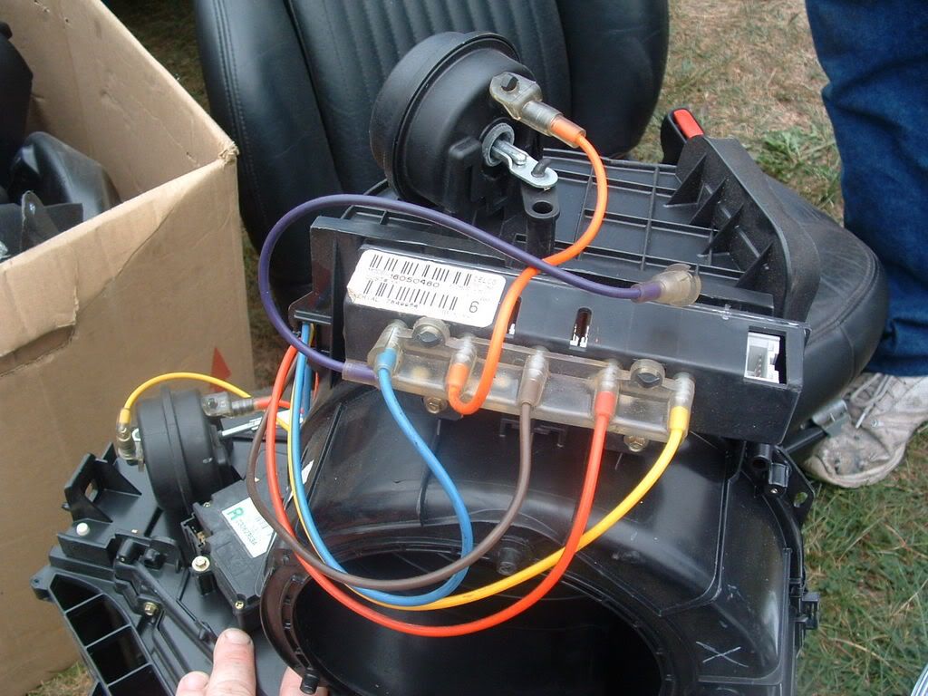
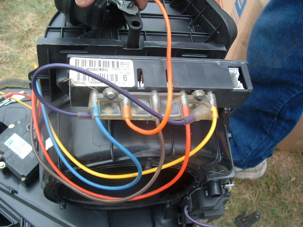
MAKE SURE that you have full VOLTAGE on the FUSE that supplies power to the HVAC Controller/Head Unit. Test it with a DC Volt Meter to chassis ground!
CLASSIC signs of under voltage to the head unit..
Bill
The HVAC Air box has a vacuum controller module that is controlled by the HVAC Controller. It has to have proper vacuum (from the reservoir) and control signals from the HVAC Control Head box.
Here is that vacuum routing controller and ALL its little vacuum lines attached to the vacuum servos:
MAKE SURE that you have full VOLTAGE on the FUSE that supplies power to the HVAC Controller/Head Unit. Test it with a DC Volt Meter to chassis ground!
CLASSIC signs of under voltage to the head unit..
Bill
Last edited by Bill Curlee; 10-04-2015 at 01:55 PM.
10-04-2015, 01:54 PM
#11
Heel & Toe
Thread Starter
Member Since: Jan 2007
Location: Odessa Florida
Posts: 17
Likes: 0
Received 0 Likes
on
0 Posts
No HVAC codes. I believe I was pulling 20 inches on the "supply side". That should eliminate any type of vacuum leak. However, I will check it again in the next couple of days. I would really like it to be a vacuum leak. I much prefer working on the engine to disassembling the dash.......
Thanks for the help, ideas, etc. I will update with the vacuum results in the next couple of days.
Thanks for the help, ideas, etc. I will update with the vacuum results in the next couple of days.
10-05-2015, 01:49 PM
#13
Heel & Toe
Thread Starter
Member Since: Jan 2007
Location: Odessa Florida
Posts: 17
Likes: 0
Received 0 Likes
on
0 Posts
Before taking the following readings the ac was blowing from all vents, floor, and defroster.
Vacuum was measured at the junction of the purple controller line and the black plastic line from the canister. At idle, it measured a constant 18 inches from the canister/manifold side (black plastic tube). The purple controller line will hold 25 inches until I disconnected the vacuum pump. This is what makes me believe there is no problem with vacuum leaks.
Voltages were taken from the controller connector disconnected from the controller. I used C1 as the ground. C5=14.1vdc, C10=12.3, C12=14.4
Thoughts??? Controller gone bad??
Last edited by hangerbum; 10-05-2015 at 06:40 PM.
10-06-2015, 01:41 PM
#14
Le Mans Master
Not at home to see the connector view to see if you got all the power feeds and grounds. However what you measured seemed OK to operate the Dual unit control.
Not sure why one if so low. Were these made with the engine running to get over 14 volts?
Mr. Sam
Not sure why one if so low. Were these made with the engine running to get over 14 volts?
Mr. Sam
10-07-2015, 06:42 AM
#16
Le Mans Master
Looked at the schematic. There is another Ground, D1. It is grounded at a different location than C1.
The Dual unit feeds a 5 Volt reference signal to the left and right Air Temp Actuators from C10. With the connector disconnected C10 on the connector should read 0 Volts.
If you don't have the schematic I will post it.
Mr. Sam
The Dual unit feeds a 5 Volt reference signal to the left and right Air Temp Actuators from C10. With the connector disconnected C10 on the connector should read 0 Volts.
If you don't have the schematic I will post it.
Mr. Sam
10-07-2015, 09:50 AM
#17
Heel & Toe
Thread Starter
Member Since: Jan 2007
Location: Odessa Florida
Posts: 17
Likes: 0
Received 0 Likes
on
0 Posts
Mr. Sam,
Using D1 I get 0vdc at C5, C10, and C12. I checked the connectivity between C1 and D1 and it ohms out at 1. Using C1 the readings are the same as previously noted.
The schematic would be helpful. Where is D1 grounded? Is it a straight ground or is it controlled?
Thanks for your help!
Using D1 I get 0vdc at C5, C10, and C12. I checked the connectivity between C1 and D1 and it ohms out at 1. Using C1 the readings are the same as previously noted.
The schematic would be helpful. Where is D1 grounded? Is it a straight ground or is it controlled?
Thanks for your help!
10-07-2015, 12:55 PM
#18
Le Mans Master
Not home but it is not controlled. In the interim just do a continuity from D1 to ground. 1 ohm from C1 to D1 is not bad, a little higher than expected but not sure of the accuracy of your meter.
Your reading of C1 to C10 is still a question to me.
Will get your the schematic.
Mr. Sam
Your reading of C1 to C10 is still a question to me.
Will get your the schematic.
Mr. Sam
10-07-2015, 05:32 PM
#19
Heel & Toe
Thread Starter
Member Since: Jan 2007
Location: Odessa Florida
Posts: 17
Likes: 0
Received 0 Likes
on
0 Posts
My answer was misleading re the connectivity between C1 & D1...... there is none. That is why I am asking about where D1 is grounded. Sorry about the miscommunication.
10-08-2015, 05:54 AM
#20
Le Mans Master
I was wrong. D1 is the ground for sensors and actuators. Sorry when I looked yesterday it was early.
Here is everything I think you need. I can provide the rest like Blower if you need it.
https://www.dropbox.com/sh/d3geon4av...GPNXv-x2a?dl=0
Mr. Sam
Here is everything I think you need. I can provide the rest like Blower if you need it.
https://www.dropbox.com/sh/d3geon4av...GPNXv-x2a?dl=0
Mr. Sam