When you click on links to various merchants on this site and make a purchase, this can result in this site earning a commission. Affiliate programs and affiliations include, but are not limited to, the eBay Partner Network.
Spal dual fan setup - installation issue - Dewitts radiator
Hi everyone. A year ago I replaced my original radiator with Dewitts and also changed to Spal dual fan setup. Then I had these issues.
Problem 1: · when fans kicked in, the battery voltage significantly drop, and the car wasn't idling normally Solution 1: · I replace my alternator with Mechman 250amp, and my voltage drop fixed as well as my car stereo system (a sub and 2 amp)
Problem 2:Couldn't fix it yet
The issue remained is that the Relays are kept burning out. At first couple days they get extremely hot, eventually, start buzzing and then break. The only relays last long were the original Spal relay, lasted for 6 months. All other relays from different brands only last for 1 week to 2 months.
I followed the Spal wiring diagram, also I
1- changed the dual fans with a new one (I thought maybe the fans are faulty and draw too much amp and cause the really to burn out) but that wasn’t the issue.
2- I replaced the entire wiring
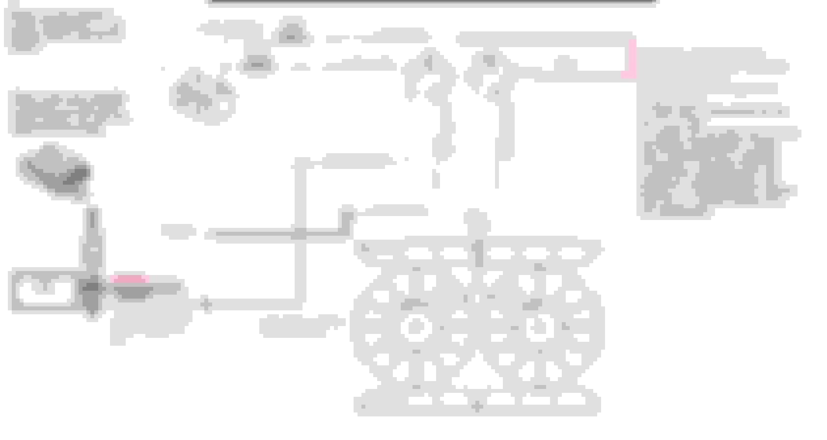
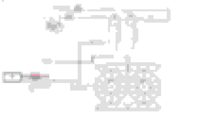
3- I attached a picture of my installation to this post.
4- Each fan draw 15amp when they start working. and each fan has 30 amp fuse.
Solution 2a (it is not a permanent solution)
When the relays are hot or buzzing, if I ground the green wire (sensor trigger), then the fans would work in full speed, and the relay buzzing will go away. Also if the relays get too hot and I ground the trigger wire (the green line), then the relays cool down quickly.
The issue with this solution is, If I use it for a long time (10 min) then it will throw a code
“P0480 – Powertrain Cooling Fan 1 control circuit “
Green wire characteristics
I don’t know precisely how this trigger wire works, and based on my research I learned it doesn’t have any voltage or current and when the car ECM sense the assigned temperature, it will ground the relay/circuit, and it is when the relay starts working.
But the green wire in my care has voltage even when the car is just startup/cold/ below the assigned temp. I connect the positive probe of the multimeter to the green wire, and a negative probe to the negative post of battery and I have a voltage reading of 5-13 volts! It fluctuates. When the temp reaches to 198F (that’s what my tuner setup), the fans kick in, and the voltage on this green wire drop to 6 volts and that’s when the relays get hot or buzzing.
I didn’t use the original fan module; please advise me if I should connect this dual fan straight to the module or how can I fix this issue.
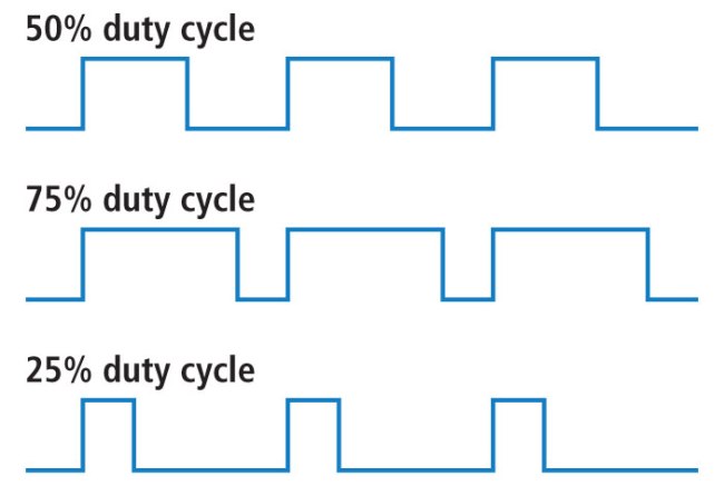
PWM signal looks like this on the negative side, and no way in hell that an anolog relay like the bosch relays is going to last that long with them cycled this much per second. Hence each time the relay is powered up to close the N.O. side, you get a touch of flash on the contacts and this repeat opening/closing of the relay contract will just burn them out, Hell, truth is, find it strange that the coil side controling the contactor set can even keep up with the pulse.
So have said that they are able to run 30amp through the oem PWM without burning it up, while my stance is not really since it only rated for 20 amps instead. If you want to run 30 amps through the OEM PWM then would go like this.
8 gauge wire across the board, with the exception of the ECM control wire and relay coil wires that can stay the same size smaller wires.
You need to go from ground to the PWM,then out of the PWM to the fan motors for the pair via black wires.
On the positive side with red wire, from the fuse box terminall with fuse 40 amp fuse in line, to a 12 volt 40 amp relay on the 30 leg, then on the 87 leg to the PWM input side.
On the relay, 85 will go to ground (does not have to be 8 gauge wire) and 86 will go your acc source to power up the coil when you start to car to allow power through the relay.
On the pwm, the M terminal are to the fans.
This will get enough power into the PWM that you don't have problems with the wires themselves, and the PWM will pulse the ground side of the fans to control them correctly.
As for how long the oem PWM lasts, as stated, it rated for 20 amp, and your pulsing 30 amps through it instead.
Or, if you want to wire the way you have it, you need 12 volt control, 20 amp load, solid state relays. Mousers sells them and they are about $20 each.
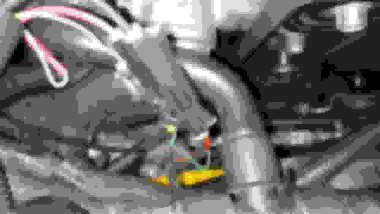
I guess you hard wired this (after looking more at post) so my wire comment is not applicable since you hard wired to battery. - I would also check the fan connector located near the top passenger side by radiator that has been know to have issues. It seems to melt and though it might be sort of working not an ideal contact and can heat things up. I see Dano523 has a nice photo of a melted connector in the background.
Last edited by double06; 04-10-2019 at 02:35 PM.
Reason: Correction
Your set up is different - I use a single 500 watt brushless fan. Here are the connectors I used on mine. I got them from Mauser they are rated at 60 amps. I used the factory wires on mine just replaced the connector. They / you need them to be sealed. You can see the difference between the factory one and the Mauser one. The contact area is about double (about size of house plug blade) so is the overall weight of connector.
Last edited by double06; 04-10-2019 at 02:56 PM.
Reason: editting
You missed the point ,and if you look at his diagram, he is using the PWM to pulse the analog relays many times a second, and this is what is burning the relay contact points out.
Sold state relays use a moffit switch design to do the switching in a DC control/DC output relay, and since they don't have metal to metal contacts that are being switched that many times a second, they will hold up much longer when being pulse driving.
Myself, would just go to a single 40 amp SPST relay to drive power to PWM that is rated at 40 amps, and let it do the pulse width modulation for the fans of the negitive side of the load isntead.
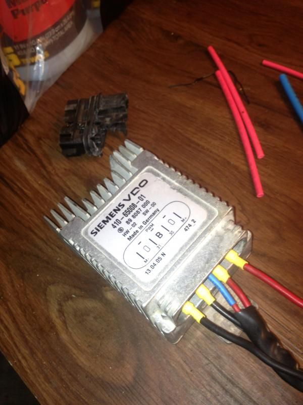
And just a FYI, but if you check out the below link, the black box that has the PWM sticker on it, it not a PWM in that sence, but just a solid state 12 volt control/50 amp solid state relay instead. Hence uses the signal from the ECM to pulse width the solid state relay that will switch that fast during the pulses per second of on and off, and will hold up long term since all the power to fans is driving through it. Hence standard solid state relay will switch off a 3 to 32 volt signal, and the ECM signal is more than enough to active the relay alone.
another cheap DC 40 amp solid state relay as well and would be dam sure to add the heat sink if you can bolt it to something that will draw the heat off them.
1. first of all sorry for my late reply, I was busy with my job and didn't have time to even go near my car. also for some reason I don't receive any notification when someone put a new comment to my post.
2. Thank you for the helpful information
3. Dano I purchased 2 solid state relay rated at 40amp each; the 25amp wasn’t available at the time I was about to buy. The 60amp was too expensive. I am going to use 30amp fuse for each relay.
4. I tried on one fan only and here is my setup. Unfortunately, the fans don’t work when the temperature reaches to 198F or above.
5. The problem is the coolant trigger wire. The voltage of that wire never exceeds above 40-60 millivolts. Therefore, the relay doesn’t activate. here is the setup.
6 - Questions I have for this section is,
A- is it normal that the original positive and negative wires for coolant fan have voltage all the time. whether the car is on or off? ( 2nd picture, look at the Notes at top of the picture)
B- is the voltage for coolant trigger wire normal? 40-60mV ( 2nd picture, Note2)
7- this trigger wire works normal and correct with my first setup. ( 2 mechanical relay, but the problem is the relay are kept burning out in short period )
When the ECU commands the fans to work, the relays either get hot or making a buzzing noise.
If I ground the sending unit, the relays cool down, buzzing noise goes away and fans work full speed.
8- I found another article online that was suggested to connect the ignition pin ( orange wire ) to the ECU sending unit. & ground the sending unit pin from the relay, but this setup doesn't work for me either. ( here is what I mean)
Please educate and help me how to solve this problem.
Thank you.
correct wiring, and the PWM is suppling the ground side on the different pulse widths to control the relay coils on the ground side of the control side. The output side of the SS relays are controling the motor power as they are being pulsed.
As for the Solid state relays you bought, there should have been a heat sinks that you could buy with them, and will need to use the heat sinks to keep the mosfit circuity from burning up.
Plus not a fan of the cheaper solid state relays, since they don't bleed off the circuitry heat as well, nor hold up as long as well. Hence there cheaper units are really more for just switch activations and holds, and not the cycling amount per second that you will be doing isntead.
So before with the mechanical relays, you where burning up the contact points, and now on the solid state, over heating the mosfit circuitry without heat sinks to pull the heat away, and now burning up the switching circuitry in the SS relay.
Hence this is the reason that you mount the SS relays directly to the metal of the radiator (metal to metal with Thermal paste between) so the radiator metal can become the heat sinks, and the thermal paste allows better heat transfer absorption.
Short of this, just pick up a PWM that will hold the 40 amps, or try to use the OEM PWM normal wiring since some have said they have luck with such instead.
Dano thank you for responding my posts quickly, but I think you didn't quite understand my question in the last post.
My setup with SSR didn't work. if you look at my first picture ( SSR diagram) that's how I did but there are no results. even swap the wiring for input side still no luck.
But if I connect the input side to a regular 3-volt battery or even to the car battery then the relay starts working. basically, the ECU wire cannot activate the SSR.
my second question is ( I think this is the main issue)
Did you connect your dual fans to the ECU or they operate separately? (either by switch or they are on when the car is on?)
Yesterday I was talking to two gentlemen from the forum, and they told me no matter I use Prospeed fan controller, (which is an SSR as you mention) or mechanical relay, I can not have the ECU to control the fans. because it draws too much amp or the signal stays open for a long time ( something like that) from signal wire which ends up getting the code
"P0480 Cooling Fan 1 Control Circuit" also the signal wire doesn't provide sufficient power to relay to activate.
The setup should be either :
1- manual, operate with a switch
2- the fans turn on as soon as the car start
Because in my setup if I want the ECU control the fans the relays (mechanical one) keep burning out, otherwise there is no issue. But it's annoying not having the ECU control the fans. Because either I should keep an eye on coolant temp to know when turning on the fans or if I wire them in a way to turn on when the car is on, it's overusing the fans and make the car to warm up slowly.
Note: I have a heat sink for the SSR, but I couldn't make them run my fans yet!
on the red line you have off the battery to the relay control side, disconnect that power wire from the relays control sides.
Out of the OEM PWM, see the two terminals marked M+ and M- that would normally go to the motor, this are the two wires/terminals out of the PWM that your going to be wiring to the control side of the SSD relays to pulse the relays.
If you are still getting a code with the PWM not seeing enough draw on the motor side of the PWM, then you can add in a resistor on the ground side with diode so the PWM is seeing more current draw on the PWM relay side like a fan was connected to it, but the relays will not see that path to ground to trigger the relays instead.
And again, PWM controls the pulse width via the M- ground side to the motor through the PWM. The B terminal is the wire from the ECM to the PWM to control it.
If you still need a diagram, will be a few days before I have time to draw one up, including adding a resitor with diode to ground on the M- to trick the PWM to think it has a fan (more current dray) connected to it.

 04-09-2019, 01:41 PM