


Pioneer AVIC RCA Fuse Fix Tutorial
Thread Starter
Drifting


Joined: Nov 2002
Posts: 1,455
Likes: 2
From: East TN
Well, after posting questions about why I was getting this terrible alternator whine and noise after a new system install I got a bunch of answers, from having wires too close together to running my amps ground wire back to the battery (and no that won't cause it). At first I blamed the defective Zapco amp, that was the most obvious source of the problem (it died after 30 minutes of play time). Also I did not use RCAs in this install, Zapcos use Symbilinks but they connect to the RCA outputs from my AVIC Z1. Someone mentioned to check the Pioneer AVIC Z1 head unit. Well, after some digging around on the internet I learned that some genius at Pioneer decided to use SMD Fuses on the board of AVIC radios. If this fuse blows your RCAs will not be grounded, it protects the main board of the AVIC from getting fried. If you send your unit in to Pioneer to replace the fuse the charge is $200, well maybe that guy wasn't too dumb that thought of this, its making Pioneer a lot of money. So if you chase every other problem, reroute your wires, and nothing works, check the fuse its not that hard. I repair amps for a hobby and decided to put my newly learned skills to use. Here is a tutorial that is from my AVIC Z1 but it should work with all the AVICs, I've seen pics of a D3 that looked almost identical but again I am not sure so if you don't have a Z series and you don't want to explore don't do it. Besides the noise and alternator whine I could no longer turn off the subwoofer from the deck, it would still play (these are common symptoms I have read other people have had also, if you know of more please post them).
Basically what I will be doing is taking the unit apart, removing the SMD mounted fuses and replacing them with an AG style fuse mounted to the back of the unit so you can replace the fuse if it blows without taking the unit apart again and messing with your soldering iron.
Basically what I will be doing is taking the unit apart, removing the SMD mounted fuses and replacing them with an AG style fuse mounted to the back of the unit so you can replace the fuse if it blows without taking the unit apart again and messing with your soldering iron.
Last edited by dan6712cc; Apr 17, 2009 at 08:28 AM.
Thread Starter
Drifting
Joined: Nov 2002
Posts: 1,455
Likes: 2
From: East TN
First, before you start I have read there is a way to check to see if your fuses are blown without taking the unit apart, the method I read about did not work for me, if you find a way that works please post it.
Before you start, make sure you open the face of the unit all the way, then turn off power to it, and remove all plugs and wires from the back.
The tools you will need are a good soldering iron, preferebly one with variable temperature, a size 8 torx screwdriver, and a phillips size 00, 0, and a size 1 screwdriver, a small flathead screwdriver, drill with appropriate sized drill bit, a voltmeter with diode/continuity check function (and a set of finely pointed probes or an SMD probe), solder, and a solder sucker might come in handy. You will also need a few 3-4 amp AG fuses and panel style fuse holders and some small gauge coated wire. If you have never soldered anything before don't try this, the SMD pieces are tiny, smaller than a pea. Also you are doing this at your own risk, you could easily turn that noisy Pioneer head unit into a very big paper weight.
Last edited by dan6712cc; Apr 17, 2009 at 04:44 PM.
Thread Starter
Drifting
Joined: Nov 2002
Posts: 1,455
Likes: 2
From: East TN
When you have the unit on your bench remove all the screws from the back plate, note which screws go where as some are different lengths. Be careful not to pull the back plate out too far as a cable attaches the fan to the board. Pop out the connector on the board from the fan and remove the plate.

Now you can remove the top plate, pull up and out and it should come out.


Looking at the unit from the top there are 4 black screws (only 2 are showing in the pic) that hold the CD/DVD playing mechanism in, remove those.

Be careful lifting this piece out as it has 2 ribbon cables and a wire attaching it to the main board.

There is a orange/brown ribbon cable and a white/silver one, I found it easiest to remove the white one from the CD/DVD playing mechanism and the orange one from the main unit that is attached right behind the hard drive. You remove the cables by pushing the flap where the cable enters up or down. The orange cable has a black flap and the white one has a brown flap. These may be difficult to open with your fingers, thats what I used the small flathead screwdriver for, after the flaps are open the ribbon comes out easily.


Now you can remove the top plate, pull up and out and it should come out.
Looking at the unit from the top there are 4 black screws (only 2 are showing in the pic) that hold the CD/DVD playing mechanism in, remove those.
Be careful lifting this piece out as it has 2 ribbon cables and a wire attaching it to the main board.
There is a orange/brown ribbon cable and a white/silver one, I found it easiest to remove the white one from the CD/DVD playing mechanism and the orange one from the main unit that is attached right behind the hard drive. You remove the cables by pushing the flap where the cable enters up or down. The orange cable has a black flap and the white one has a brown flap. These may be difficult to open with your fingers, thats what I used the small flathead screwdriver for, after the flaps are open the ribbon comes out easily.
Last edited by dan6712cc; Apr 17, 2009 at 04:54 AM.
Thread Starter
Drifting
Joined: Nov 2002
Posts: 1,455
Likes: 2
From: East TN
Now you can remove the wire that runs from the CD/DVD unit to the main unit, unplug it from the main unit.

The black trim that the face slides into is held on by some very small screws that have blue locktite on them, you need the 00 phillips screwdriver to remove them. There are two on each side of the unit and three on the front of the unit (one is hiding underneath the ribbon cable that goes from the face to the main unit). While you are looking at the face you can remove the one black screw underneath the HDD door, then remove the two torx screws from the HDD door with a size 8 torx driver. The HDD door will then come out (and the screws will stay attached to the door, don't worry about loosing them).


Now you can remove the hard drive by pulling the black plastic tab sticking out at you.

The black trim should now slide forward and give you access to ribbon cables you need to remove in order to separate the top from the bottom half of the main unit.

With the screen of the unit facing you and the trim pulled back you can see an orange/brown cable on the right and a white/silver cable on the left. I had to use the small flathead screwdriver on these to remove them. I opened up the flaps to them from where they enter the bottom of the unit, take your time these are not that easy to get to.


Now remove the screws from the side of the unit that I have marked in the pic and you can carefully lift the top half of the unit from the bottom half exposing the circuit board that has the SMD mounted fuses. Before lifting the top half off completely remove the plug that contains a bundle of wires connecting the top to bottom half of the unit.


The black trim that the face slides into is held on by some very small screws that have blue locktite on them, you need the 00 phillips screwdriver to remove them. There are two on each side of the unit and three on the front of the unit (one is hiding underneath the ribbon cable that goes from the face to the main unit). While you are looking at the face you can remove the one black screw underneath the HDD door, then remove the two torx screws from the HDD door with a size 8 torx driver. The HDD door will then come out (and the screws will stay attached to the door, don't worry about loosing them).
Now you can remove the hard drive by pulling the black plastic tab sticking out at you.
The black trim should now slide forward and give you access to ribbon cables you need to remove in order to separate the top from the bottom half of the main unit.
With the screen of the unit facing you and the trim pulled back you can see an orange/brown cable on the right and a white/silver cable on the left. I had to use the small flathead screwdriver on these to remove them. I opened up the flaps to them from where they enter the bottom of the unit, take your time these are not that easy to get to.
Now remove the screws from the side of the unit that I have marked in the pic and you can carefully lift the top half of the unit from the bottom half exposing the circuit board that has the SMD mounted fuses. Before lifting the top half off completely remove the plug that contains a bundle of wires connecting the top to bottom half of the unit.
Last edited by dan6712cc; Apr 17, 2009 at 08:33 AM.
Thread Starter
Drifting
Joined: Nov 2002
Posts: 1,455
Likes: 2
From: East TN
Now you can verify if and which fuses are actually blown with your DVM.


The fuses are white in color and are close to the connectors on the back of the unit, also they have a symbol next to them with an exclamation point inside a triangle. Two fuses say SOC 72V T 3.15A and one has a "P" on it. Fuse FU1204 says GNDV, FU1400 says GND_AUD, and FU1201, the one that was blown, says GND_AUD. I have found 3 of them, only one was blown. I'm going to replace them with a slow blow 3 amp AG fuse, actually I will use a 4 amp but if you want to be safer use a 3 amp. The fuses and fuse holders I got from parts express, the part numbers and prices are: 071-510 Littelfuse 3AG Panel Fuseholder $1.55, and 071-704 Littelfuse 4A 3AG Slow Blow Fuse 5 Pcs. $3.22.
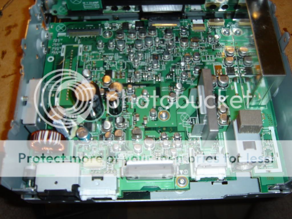


To verify if the fuses are blown set your DVM to diode/continuity check and place the probes on either side of the fuse right on top of the solder joints. If the fuse is good you will hear a beep or confirmation on your screen, the screen may change from 0L to some number then to .000 very quickly, if its bad you won't hear anything and the screen will not change from 0L. So if its bad the connection has broken and there is no continuity, if its good the circuit is intact.


The fuses are white in color and are close to the connectors on the back of the unit, also they have a symbol next to them with an exclamation point inside a triangle. Two fuses say SOC 72V T 3.15A and one has a "P" on it. Fuse FU1204 says GNDV, FU1400 says GND_AUD, and FU1201, the one that was blown, says GND_AUD. I have found 3 of them, only one was blown. I'm going to replace them with a slow blow 3 amp AG fuse, actually I will use a 4 amp but if you want to be safer use a 3 amp. The fuses and fuse holders I got from parts express, the part numbers and prices are: 071-510 Littelfuse 3AG Panel Fuseholder $1.55, and 071-704 Littelfuse 4A 3AG Slow Blow Fuse 5 Pcs. $3.22.
To verify if the fuses are blown set your DVM to diode/continuity check and place the probes on either side of the fuse right on top of the solder joints. If the fuse is good you will hear a beep or confirmation on your screen, the screen may change from 0L to some number then to .000 very quickly, if its bad you won't hear anything and the screen will not change from 0L. So if its bad the connection has broken and there is no continuity, if its good the circuit is intact.
Last edited by dan6712cc; Apr 17, 2009 at 04:41 AM.
Thread Starter
Drifting
Joined: Nov 2002
Posts: 1,455
Likes: 2
From: East TN
At this point you need to unsolder the offending fuse. I like to heat one joint then quickly move to the opposite side and using the tip of the iron push the fuse as the solder is being heated to remove the fuse.

Then strip some small gauge (I used 20) wire and tin the tips, make sure the tips are short.


Then strip some small gauge (I used 20) wire and tin the tips, make sure the tips are short.
Last edited by dan6712cc; Apr 22, 2009 at 08:49 PM.
Thread Starter
Drifting
Joined: Nov 2002
Posts: 1,455
Likes: 2
From: East TN
Then solder the tips to the board where the fuse was. I prefer placing the soldered ends of the wire on top of the joint then touching the iron tip to the wire which melts the tip solder and the joint solder .

At this point you should have something that looks like this.

Do this for as many fuses as are blown. Next you will assemble everything in the reverse of how it was opened, route the wires you just soldered to the hole in the bottom back right hand corner if the screen is facing away from you as shown in this following pic. You also have the option of drilling a hole in the back plate and mounting the fuse flush but this way everything can be put back to how it was originally if you want. Make a knot in the two wires right before they exit so if you tug on them they won't rip out of the board.

Place a heat shrink on the wires just bigger than the fuse holder and solder the fuse holder on the wires, heat the shrink wrap, install the fuse and you're done!


At this point you should have something that looks like this.
Do this for as many fuses as are blown. Next you will assemble everything in the reverse of how it was opened, route the wires you just soldered to the hole in the bottom back right hand corner if the screen is facing away from you as shown in this following pic. You also have the option of drilling a hole in the back plate and mounting the fuse flush but this way everything can be put back to how it was originally if you want. Make a knot in the two wires right before they exit so if you tug on them they won't rip out of the board.
Place a heat shrink on the wires just bigger than the fuse holder and solder the fuse holder on the wires, heat the shrink wrap, install the fuse and you're done!
Last edited by dan6712cc; Apr 23, 2009 at 05:32 PM.
Thread Starter
Drifting
Joined: Nov 2002
Posts: 1,455
Likes: 2
From: East TN
Also if anyone knows what the FU1400 fuse with a "P" on it is rated it would help if someone has blown one of those and needs a replacement AG style fuse.
Found it, the P fuse it rated at 3 amps, 32 volts, and 0.020 ohms cold.
If you have trouble putting the ribbon cables back in or even taking them out what you can do to slide the black trim back further, or in this case remove it completely is to remove the two silver screws that the screen tilts on. One screw with have a spring on it so be careful not to loose that, you can then remove the ribbon cable that is attached to the screen at the point where it attached to the main unit.
Last edited by dan6712cc; Apr 23, 2009 at 05:42 PM.
Corvette Stories
The Best of Corvette for Corvette Enthusiasts

How Much Horsepower Every Corvette Engine "LOST" in 1972
Joe Kucinski
Top 10 DOs and DON'Ts for Protecting Your Convertible Top!
Michael S. Palmer
Top 10 Most Explosive Corvettes Ever Made: Power-to-Weight Ratio Ranked!
Joe Kucinski
150 hp to 1,250 hp: Every Corvette Generation Compared by the Specs That Matter
Joe Kucinski
8 Coolest Corvette Pace Cars (and Replicas) of All Time
Verdad Gallardo
Top 10 Corvette Engines RANKED by Peak Torque (70+ Years of Muscle!)
Joe Kucinski
Corvette ZR1X Will Be Pacing the Indy 500, And Could Probably Race, Too!
Verdad Gallardo
Top 10 Corvettes Coming to Mecum Indy 2026!
Brett Foote
Top 10 C9 Corvette MUST-HAVES to Fix These C8 Generation Flaws!
Michael S. Palmer
Thread Starter
Drifting
Joined: Nov 2002
Posts: 1,455
Likes: 2
From: East TN
Straight from Perry Babins Tutorial on Amp Repair regarding grounding the RCA wires:
"The fuses are necessary to prevent a fire hazard. If you use an unfused wire and the owner of the vehicle allows the shields to short to the power wire again, the unfused jumper will violently burn open (lots of smoke and flames). If the problem is an amplifier with an intermittently shorted transformer, the fuses will likely prevent the power supply transistors from being destroyed."
Last edited by dan6712cc; Apr 17, 2009 at 10:05 AM.


Thread Starter
Drifting
Joined: Nov 2002
Posts: 1,455
Likes: 2
From: East TN
Yeah, it is a lot of work, pioneer should have done what I'm doing in this tutorial, if you do this though it will only take a few minutes to swap in a new fuse and you don't have to open up the unit. I still think it beats paying pioneer $200 to replace a fuse. The fuse can blow if you have a bad ground, or probably more commonly if you hot swap the RCAs (pull them out of the amp/head unit or switch them around when the system is on). It could also happen if you accidently touch the negative and positive wires from the head unit or to the amp, or if a 12 volt power source comes in contact with the shield..
Last edited by dan6712cc; Apr 17, 2009 at 10:28 AM.
Team Owner


Joined: Feb 2000
Posts: 51,504
Likes: 6
From: Sacramento CA
Thread Starter
Drifting
Joined: Nov 2002
Posts: 1,455
Likes: 2
From: East TN
Thread Starter
Drifting
Joined: Nov 2002
Posts: 1,455
Likes: 2
From: East TN
All done, if you find any mistakes or tips please let me know. Besides the alternator whine and noise with the car off that this problem caused, now I verified it also fixed the problem of not being able to turn off the subwoofer from the head unit.
Thread Starter
Drifting
Joined: Nov 2002
Posts: 1,455
Likes: 2
From: East TN
I can't say for sure but I would expect all the newer pioneer units to use the same SMD fuses. There is a way to test it without opening the unit up, maybe someone on here will have better luck with that method than I did and post how they did it.
Pro


Joined: Jan 2002
Posts: 741
Likes: 9
From: Rancho Cordova CA
I have been fighting a "ground loop issue" for a week when I decided to do a bit more research and found this post. I also read about the issue on AVC411.com. I was a bit concenred about ruining my $1500 head unit but went with it. Your instructions were clear and spot on. The only thing I had any problems on was the white ribbon cable on the DVD CD deck. It was tough to get back on. All else was fine. The unit is back in the car and the ****ty noise is now gone. I was not only getting alternator whine but also a clicking noise and then additional noise when my HIDs came on. Thanks again for the write up.


PS whole job took me about three hours due to my very gently handling of my head unit. If I did this on another car I am thinking two hours and then maybe 1.5. Just like anything else the first time is a tough.
PS whole job took me about three hours due to my very gently handling of my head unit. If I did this on another car I am thinking two hours and then maybe 1.5. Just like anything else the first time is a tough.
Last edited by Steve'01; Aug 20, 2009 at 07:11 PM.
Team Owner


Joined: Jan 2004
Posts: 23,220
Likes: 3
From: HOUSTON
St. Jude Donor '06 thru '15, '19
I think this is what happened to my D3 , ??? I had no whine , then messing with the amp I might have blown something and have a really nasty whine now ?????
Also will the ground loop isolator fix this or will I still have to tear it apart , I do not want to have to do it
Also will the ground loop isolator fix this or will I still have to tear it apart , I do not want to have to do it
Last edited by mojo1; Aug 26, 2009 at 12:40 PM.