M.A.D. Wiring making me Mad!
 07-03-2011, 08:00 PM
#1
Melting Slicks


Thread Starter

Im finally getting to this wiring mess on my 63. I have the new Lectric Limited stock harness. I also purchased the M.A.D. relay system because of the added electrical accessories I have.
I'm trying to figure out his voltage sensing hook up from the "lighting harness". The red power up wire and the "brown" wire that triggers the regulator.
1st problem is the "lighting" harness doesn't have a red power up wire. That wire is actually in the ignition harness, as Doc rebuilds schematics show it.
2nd Problem is I'm supposed to reroute the "small gauge brown" wire with the red power wire. Again the there is no brown wire in the "lighting Harness". And there is no brown wire in the ignition harness either.
So, you 63' guru's, which wire in the "ignition harness" would be the voltage regulator wire that might be the trigger wire? I've narrowed it down to the black/pink wire? I can't even find a brown wire, even in my old harness.
This setup is supposed to work with the new late model alternators with internal regulators.
I know some have done this conversion as I remember reading about it 3+ years ago.
Thanks, Mike S.
 07-04-2011, 01:00 AM
#2


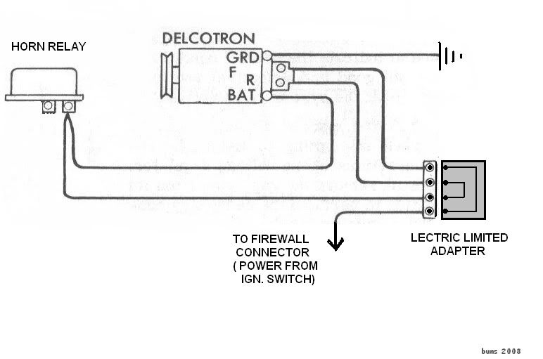
Also, for those that are interested in switching to an internally regulated alternator, here is a schematic of the adaptor that is available. As you can see it just reroutes the stock wiring so you could do it yourself if so inclined.

 07-04-2011, 11:49 AM
#4
Le Mans Master

Member Since: Nov 2000
Location: Going too fast over the hill. Iowa
Posts: 7,246
Likes: 0
Received 18 Likes
on
16 Posts

If the relay system is supposed to power additional accessories, it should obtain the power for the accessories from the "buss" screw terminals on the horn relay. If enough extra power is needed that the original alternator needs to be upgraded, I suggest that you add a 10ga red wire from the alternator output to the horn relay buss.
The power to trigger the relays should come from the brown wire that originates at the ignition switch acc(essory) terminal to power the gauges and wipers whenever the key switch is in the on or acc position.
Note that both red and brown are unfused lines.
The power to trigger the relays should come from the brown wire that originates at the ignition switch acc(essory) terminal to power the gauges and wipers whenever the key switch is in the on or acc position.
Note that both red and brown are unfused lines.
Last edited by magicv8; 07-04-2011 at 02:23 PM.
07-04-2011, 01:23 PM
#5
Melting Slicks
Thread Starter
Great drawing Buns! I am not using the external regulator. In fact what is creating alot of my confusion is where I've started and where I'm tring to get to.
I have replaced the old harnesses with all new stock harnesses and ordered the 3wire alternator system moved to the drivers side (Change one).
I've ordered the M.A.D. voltage sensing, relay kit(s), Alternator with 3-wire internal reg, and startum-up remote solenoid sarter kit (Changes 2a,b,c, and d).
The engine came with a 1-wire 100 amp Proform alternator but I am going to swap the internal regulator for a 3-wire to match the way I ordered the harness(change 3).
My starter is a mini sarter which throws another wrench into the mix as the the "S" and "R" terminals are wired differently through the remote solenoid (Change 4). (Though I think I have that one figured out).
I have routed the battery cables to the Z-bar through a battery disconnect switch and then to the remote solenoid (Change 5).
I'm beginning to get confused now This M.A.D. system looked easy and I spoke with the owner at length and he explaned it well. But somethings aren't adding up.
Magic metioned the brown wire from the Ign switch. But M.A.D. has me removing the black/pink wire and connecting it to the 12 GA red in the connector, which leaves the brown wire dead ended in the firewall connector???
This car hasn't been on the road since 1987 and the restore is 95% complete except for the seats and wiring. It looks like the wiring may be another 10 years in the making!
I have replaced the old harnesses with all new stock harnesses and ordered the 3wire alternator system moved to the drivers side (Change one).
I've ordered the M.A.D. voltage sensing, relay kit(s), Alternator with 3-wire internal reg, and startum-up remote solenoid sarter kit (Changes 2a,b,c, and d).
The engine came with a 1-wire 100 amp Proform alternator but I am going to swap the internal regulator for a 3-wire to match the way I ordered the harness(change 3).
My starter is a mini sarter which throws another wrench into the mix as the the "S" and "R" terminals are wired differently through the remote solenoid (Change 4). (Though I think I have that one figured out).
I have routed the battery cables to the Z-bar through a battery disconnect switch and then to the remote solenoid (Change 5).
I'm beginning to get confused now
This M.A.D. system looked easy and I spoke with the owner at length and he explaned it well. But somethings aren't adding up.Magic metioned the brown wire from the Ign switch. But M.A.D. has me removing the black/pink wire and connecting it to the 12 GA red in the connector, which leaves the brown wire dead ended in the firewall connector???
This car hasn't been on the road since 1987 and the restore is 95% complete except for the seats and wiring. It looks like the wiring may be another 10 years in the making!
07-04-2011, 02:02 PM
#6
Burning Brakes

Member Since: Jan 2005
Location: Leavenworth Washington
Posts: 768
Likes: 0
Received 0 Likes
on
0 Posts

While I didn't do the MAD thing to my Corvette, I did do it to my 70 El Camino and it is the bomb. My 3 wire alternator runs the system at 14.2V with the sense wire back on the firewall vice the horn relay, keeps my battery really happy, and just makes for an easier way to figure out what the hell is going on. I put in the Starter Relay system as well and understand the confusion with the Hi Torque starter. I had to actually wire in another relay because there was a concern if the permanent magnet starter didn't actually disengage, it would try to become a generator which would not be a good thing. When I was done I had added a couple relays so that I was not sourcing power to things like headlights through the bulkhead connectors. I am looking for my old MAD instructions to see if I can't figure out what is going on with your wires.
G
G
07-10-2011, 09:49 AM
#7
Melting Slicks
Thread Starter
Well I pretty much got the M.A.D. wiring installed and I think it's all according to his instructions.
I ran into one question though. When I rerouted the black/pink wire, I found out it is actually about a 20 gauge single strand rather than multi copper strand. Also it seems to go back toward the passenger side of the car but the schematics do not show a black/pink wire anywhere except the regulator connector to fuse block connector. ??? Is it possible the wire is just looped that direction and doubles back? I did order the harness with the alt/reg on the driverside.
I also no longer have a "Battery Gauge", I had it converted to a volt meter. Since that thing was in series in the circuit, did I interupt power to anything now that the gauge no longer exists?
07-10-2011, 01:09 PM
#9
Burning Brakes
Member Since: Jan 2005
Location: Leavenworth Washington
Posts: 768
Likes: 0
Received 0 Likes
on
0 Posts
Get rid of the solid strand wire. It gets brittle and will break off after a time of vibration. One of the major reasons we use stranded wire in aircraft.
07-10-2011, 04:15 PM
#10
I've never seen this mentioned before so I have no clue as to what it's supposed to accomplish.
07-11-2011, 06:52 PM
#11
Melting Slicks
Thread Starter
I still have to unwrap the harness going to the passenger side to verify that single strand wire just loops and comes back. I checked every black and pink wire with an ohmeter and none of them show continuity.
Anyway, thanks alot guys, I feel much more comfortable having run this by you before I started cutting into a brand new harness.