Help Wiring Engine Test Stand
 11-19-2011, 10:47 PM
#1
Burning Brakes

Thread Starter
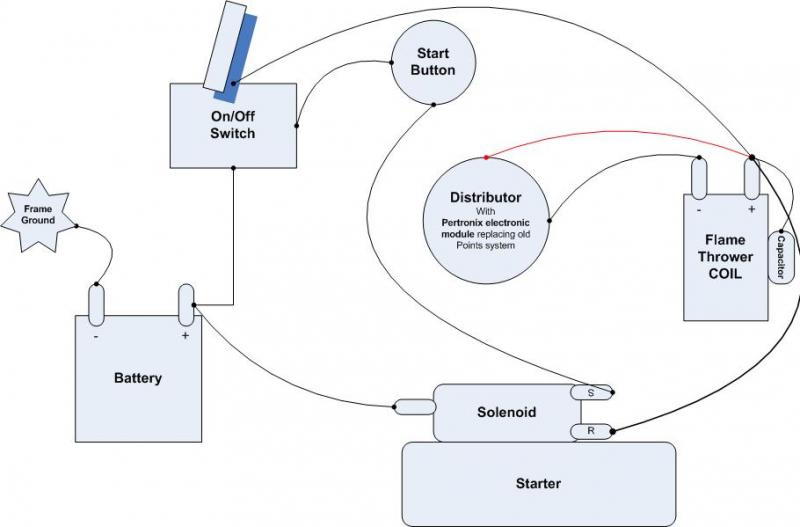
Wiring up my new test stand. See diagram below for accuracy.
Am I missing anything?
What gauge wire for the solenoid, coil, etc.? I got the gauge numbers in the pic from the AIM.
Is there a ground off the ignition switch? There is a center post on my switch that is not labeled.

Am I missing anything?
What gauge wire for the solenoid, coil, etc.? I got the gauge numbers in the pic from the AIM.
Is there a ground off the ignition switch? There is a center post on my switch that is not labeled.
 11-19-2011, 11:00 PM
#2
Drifting

You need to put a resistor in the 18 gauge pink wire from the ignition switch to the + side of the coil. An OEM style ballast resistor will do, or a coil with a built in resistor---either one will work.
RON
Last edited by rongold; 11-19-2011 at 11:02 PM.
11-19-2011, 11:56 PM
#3
Melting Slicks

You might consider losing the ignition switch and simply wiring in a starter button and a kill switch to the coil. Simpler and you can crank the motor over with the button with the kill switch cutting current to the coil. This is convenient if you need to bump the motor over for adjustments or build oil pressure prior to starting. 
11-20-2011, 12:02 AM
#4
Burning Brakes
Thread Starter
I'm running a flame thrower coil which I believe already has the resistor?
11-20-2011, 08:15 AM
#5
Race Director

Member Since: Feb 2007
Location: northern california
Posts: 13,613
Received 6,529 Likes
on
3,004 Posts
C2 of Year Finalist (track prepared) 2019

You definitely need either a ballast resistor or a coil that functions without one. Mount the resistor on a stand off, so it gets plenty of cooling air around it:
It may pay you to also go beyond the "get'er done" approach of just doing the minimum needed to make the engine run. What if something goes horribly wrong while your engine under test is running?
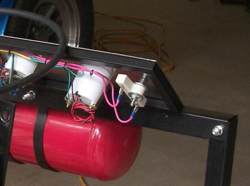
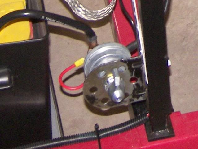
You'd want a kill switch for all the electric circuits. This needs to be right at the battery. If you have an alternator on the engine, the switch needs to be a two-pole, single throw type so you can interrupt not only the battery lead but also the alternator output:
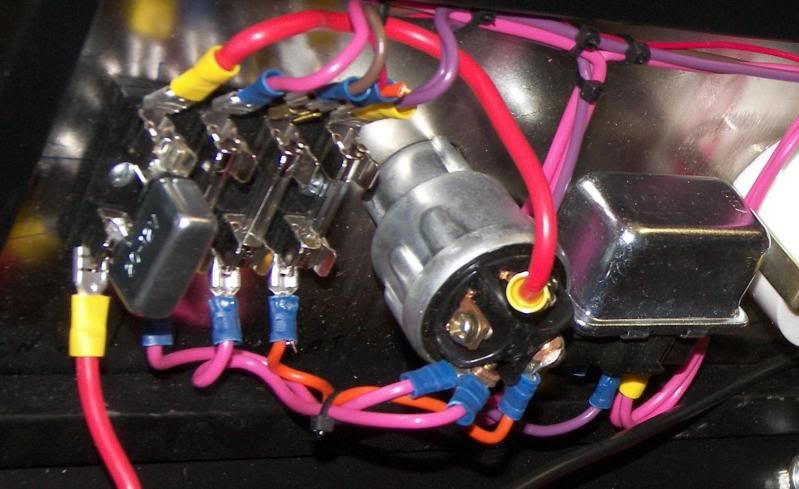
You should also consider adding a master circuit breaker (silver rectangle, left) and individual fuses for the various support circuits, like gauges, ignition, starter solenoid:
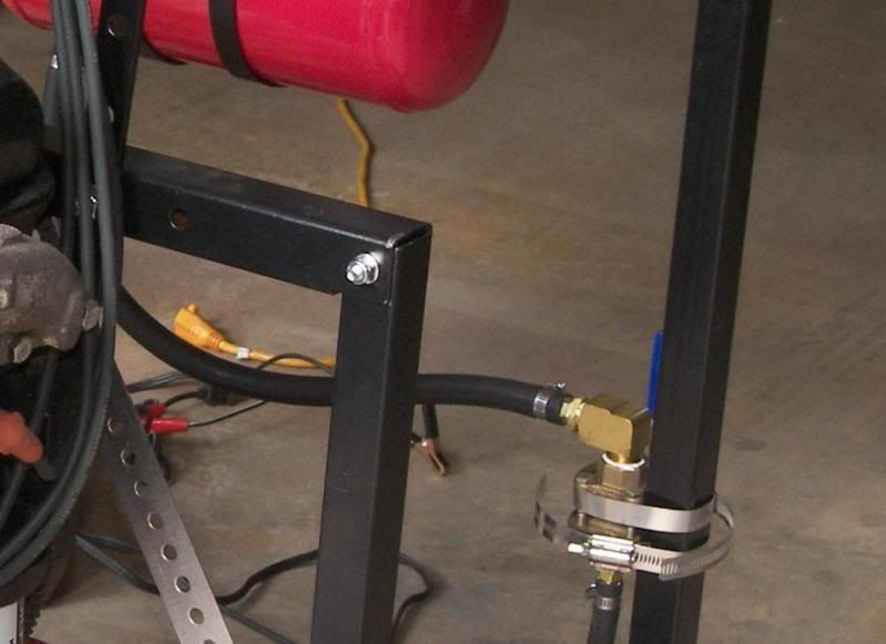
And, in my opinion, most importantly, always add a fuel cut off valve:
Go the extra distance to include these things and, if something goes really wrong, you've got a chance to do a safe shut down.

Jim
It may pay you to also go beyond the "get'er done" approach of just doing the minimum needed to make the engine run. What if something goes horribly wrong while your engine under test is running?
You'd want a kill switch for all the electric circuits. This needs to be right at the battery. If you have an alternator on the engine, the switch needs to be a two-pole, single throw type so you can interrupt not only the battery lead but also the alternator output:
You should also consider adding a master circuit breaker (silver rectangle, left) and individual fuses for the various support circuits, like gauges, ignition, starter solenoid:
And, in my opinion, most importantly, always add a fuel cut off valve:
Go the extra distance to include these things and, if something goes really wrong, you've got a chance to do a safe shut down.
Jim
 11-20-2011, 01:53 PM
#7
Race Director
Member Since: Feb 2007
Location: northern california
Posts: 13,613
Received 6,529 Likes
on
3,004 Posts
C2 of Year Finalist (track prepared) 2019
Thanks for the kind words. Yep, those detail shots are of the engine test stand I made for my own use.
Can't help thinking about "worst case" scenarios and trying to plan for them. I'm an engineer.... or was, back when I was a productive member of society.
Jim
Can't help thinking about "worst case" scenarios and trying to plan for them. I'm an engineer.... or was, back when I was a productive member of society.
Jim
11-20-2011, 02:03 PM
#8
Team Owner


Member Since: Oct 2000
Location: Washington Michigan
Posts: 38,899
Received 1,857 Likes
on
1,100 Posts

Not as classy as Jim's, but one of my older pre-run setups (on my Grand Sport chassis) is shown below - partial cluster and key components mounted on a 2x4 "dash" zip-tied on the frame.
First photo shows the engine side - the ballast resistor is on the left, then the Mallory coil, then two junction blocks - one +12V, and one for ground. Second photo shows the driver's view. I used a one-piece harness for the whole car - that's why you see all the un-used circuits coiled up. Neighbors weren't real excited about the open 4" sidepipes.
First photo shows the engine side - the ballast resistor is on the left, then the Mallory coil, then two junction blocks - one +12V, and one for ground. Second photo shows the driver's view. I used a one-piece harness for the whole car - that's why you see all the un-used circuits coiled up. Neighbors weren't real excited about the open 4" sidepipes.
06-08-2012, 02:05 PM
#9
Heel & Toe


Member Since: Sep 2010
Posts: 15
Likes: 0
Received 0 Likes
on
0 Posts

Hello,
Could someone help me understand what I might be doing wrong with the below wiring? I get the car to start but it imediately dies. I think somehow I lose spark. Can someone lead me in the right direction?
Thanks in advance for your help.
Bruce
Could someone help me understand what I might be doing wrong with the below wiring? I get the car to start but it imediately dies. I think somehow I lose spark. Can someone lead me in the right direction?
Thanks in advance for your help.
Bruce
Last edited by bowens24; 06-08-2012 at 10:52 PM.
06-08-2012, 02:28 PM
#10
Le Mans Master


Very nice Jim, how about a photo of the whole stand?
06-08-2012, 08:48 PM
#11
Team Owner
Member Since: Oct 2000
Location: Washington Michigan
Posts: 38,899
Received 1,857 Likes
on
1,100 Posts
Is the device on the side of the coil a "resistor", or a capacitor?
06-08-2012, 10:15 PM
#12
Heel & Toe
Member Since: Sep 2010
Posts: 15
Likes: 0
Received 0 Likes
on
0 Posts
06-09-2012, 11:14 AM
#13
Le Mans Master
Seems like that's what would happen if the coil wasn't correctly getting power from the on/off switch.
06-09-2012, 01:43 PM
#14
Team Owner
Member Since: Oct 2000
Location: Washington Michigan
Posts: 38,899
Received 1,857 Likes
on
1,100 Posts
 06-10-2012, 02:17 PM
#16
Heel & Toe
Member Since: Sep 2010
Posts: 15
Likes: 0
Received 0 Likes
on
0 Posts
that was my problem. Thank for the help. The switch has two ON's and if it is switched to one side only one side has power. I was using all three terminals, now I am using only 2 terminals. She starts and runs now.
Bruce
05-04-2013, 08:21 AM
#17
Drifting
How will the wiring diagram (from Bowens24 be changed if the generator is included in the cct (used to keep tension on the fan belt to run the water pump?
05-04-2013, 04:54 PM
#18
Team Owner
Member Since: Oct 2000
Location: Washington Michigan
Posts: 38,899
Received 1,857 Likes
on
1,100 Posts
 05-04-2013, 06:55 PM
#20
Team Owner

Here is a engine start box I built that is now mounted to a Start Stand I'm building.