Air Conditioning troubleshooting
 05-06-2012, 04:08 PM
#41
Race Director


After reading post #33, my gut told me that BOTH high and low side pressures seem too high............especially the high side! I looked at some online refrigeration charts for R134a and they confirm this gut feeling.
I have some experience with R12 and R22 systems, but none with R134a. I also have no experience with the ancient system found on midyear Corvettes. Do these early systems use a capillary tube, or an expansion valve to accomplish the isothermal expansion (throttling)? Was it necessary to use a different orifice size in the expansion valve, or a different ID cap tube when the conversion was done? Since you had nothing to do with the conversion, maybe you should look into this.
44 ounces of refrigerant sounds about right, so overcharging doesn't strike me as a possibility, but, you never know.
Conversion to 134a does not require a change to the expansion valve. However, it recommends a setting change to the STV or POA valve on the compressor suction to keep the evaporator from freezing at low AC loads.
The recommended charge for 134a refrigerant for a conversion is 80-90 percent of the R12 amount. The R12 capacity for this system is 3 lbs or 48 oz. That is why I recommended 3, 15 oz cans of 134a be used (45 oz total.....assuming that every bit of the 134a in the cans goes into the system....which is HIGHLY unlikely). Tim probably has a 85-90 percent charge.
Larry
Last edited by Powershift; 05-06-2012 at 04:32 PM.
 05-06-2012, 04:42 PM
#42
Racer

Thread Starter
Member Since: May 2006
Location: Fairfield County Connecticut
Posts: 364
Likes: 0
Received 0 Likes
on
0 Posts

I may not resume working on this project today as I have other commitments, but I will report back when I can in a few days. Going over your reply, I think the excess air is definitely a possibility.
Thanks
Tim
05-06-2012, 05:37 PM
#43
Racer
Thread Starter
Member Since: May 2006
Location: Fairfield County Connecticut
Posts: 364
Likes: 0
Received 0 Likes
on
0 Posts
Larry - another development - I had a few minutes before my company arrives to try your procedure of bleeding some air and checking the the hot water valve.
1 - the valve you refer to I assume has a vacuum tube hooked to it as well as a water hose coming from the top of the motor and then a short hose and pipe going through the firewall and then into the heater core - is that correct?
well, the short pipe that travels through the fire wall was hot - so I assume that valve is bad and and letting hot water into the heater core and thus fighting with the cold air the ac is trying to produce?
2 - I bled a small amount of air from both the high and low side - my high gauge no reads about 260, but I still have foam in the sight glass.
3 - this is a new development of greatest concern - There is (was) an inline fuseholder in the engine compartment hooked to a 3 prong connector that plugs into a small box on the outside of the heater box in the engine compartment. My doc rebuild wiring diagram calls this 3 prong connector an (AC RELAY). It started smoking while I was checking things so I immediately turned off the air, shut the motor off and disconnected the battery before any damage was done other than start to melt the fuseholder. My electrical backround tells me it was a weak connection between the fuseholder contact and the fuse. So I opened the fuseholder and kept it separated and taped and insulated each end until I can replace it. Everything seems to still be working - the ac clutch engages, but the blower motor of course no longer operates. My wiring diagram lists this as a 35 amp fuse - kind of big for just the blower motor - my non AC 64 has no such fuseholder. I'll go back and check my shop manual to further investigate what else this controls.
Here's my questions
1 - do you know what else this fuseholder controls?
2 - do I assume I need to replace the water valve or is there a repair procedure?
Thanks
Tim
05-06-2012, 06:06 PM
#44
Tech Contributor

1 - the valve you refer to I assume has a vacuum tube hooked to it as well as a water hose coming from the top of the motor and then a short hose and pipe going through the firewall and then into the heater core - is that correct?
well, the short pipe that travels through the fire wall was hot - so I assume that valve is bad and and letting hot water into the heater core and thus fighting with the cold air the ac is trying to produce?
well, the short pipe that travels through the fire wall was hot - so I assume that valve is bad and and letting hot water into the heater core and thus fighting with the cold air the ac is trying to produce?
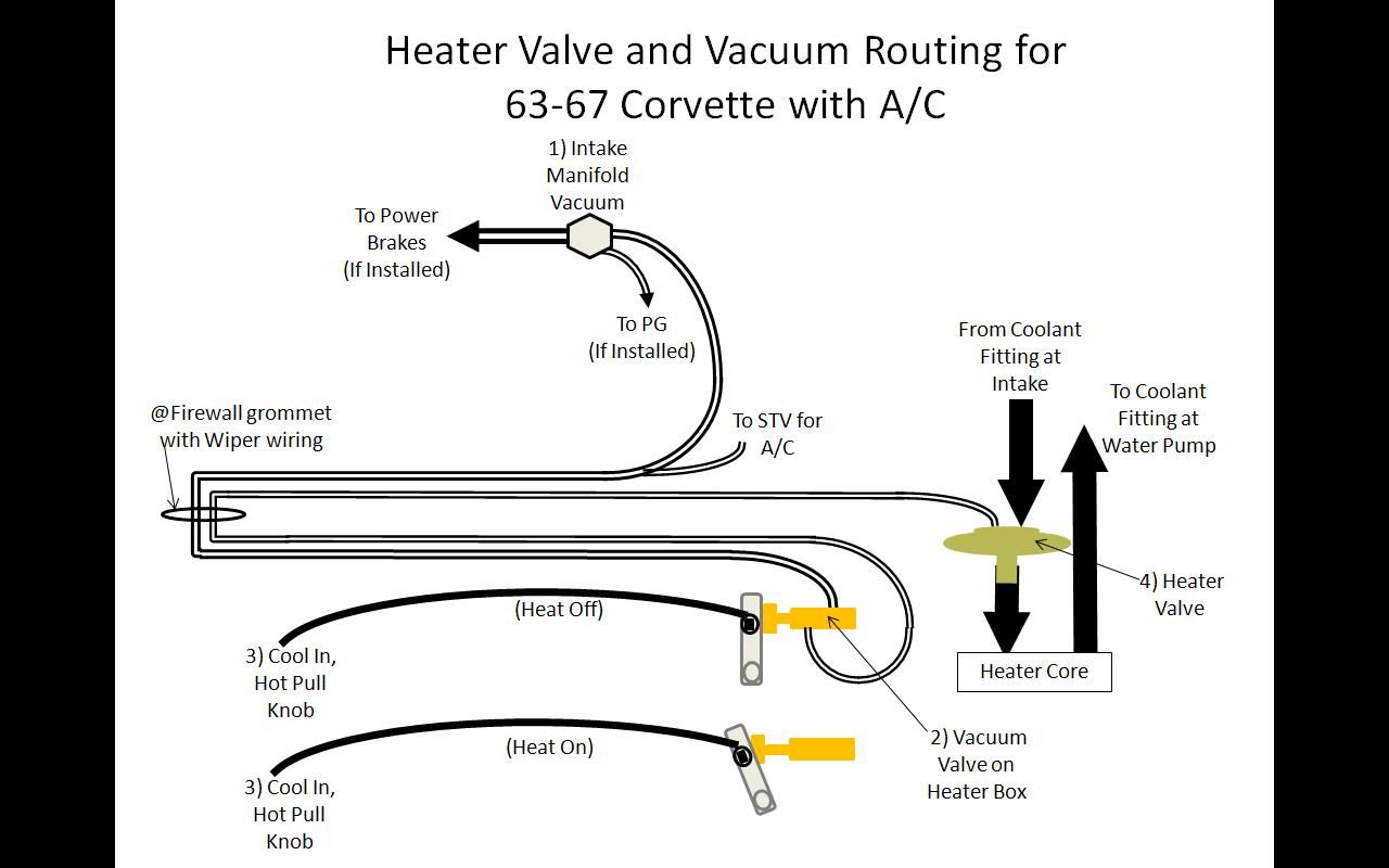
Here's the valve on the heater box, circled:
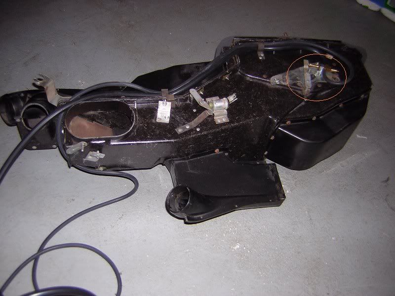
And here's the overall circuit. The large black arrows for the coolant indicate direction of flow.
 05-06-2012, 06:30 PM
#45
Race Director
Larry - another development - I had a few minutes before my company arrives to try your procedure of bleeding some air and checking the the hot water valve.
1 - the valve you refer to I assume has a vacuum tube hooked to it as well as a water hose coming from the top of the motor and then a short hose and pipe going through the firewall and then into the heater core - is that correct?
well, the short pipe that travels through the fire wall was hot - so I assume that valve is bad and and letting hot water into the heater core and thus fighting with the cold air the ac is trying to produce?
2 - I bled a small amount of air from both the high and low side - my high gauge no reads about 260, but I still have foam in the sight glass.
3 - this is a new development of greatest concern - There is (was) an inline fuseholder in the engine compartment hooked to a 3 prong connector that plugs into a small box on the outside of the heater box in the engine compartment. My doc rebuild wiring diagram calls this 3 prong connector an (AC RELAY). It started smoking while I was checking things so I immediately turned off the air, shut the motor off and disconnected the battery before any damage was done other than start to melt the fuseholder. My electrical backround tells me it was a weak connection between the fuseholder contact and the fuse. So I opened the fuseholder and kept it separated and taped and insulated each end until I can replace it. Everything seems to still be working - the ac clutch engages, but the blower motor of course no longer operates. My wiring diagram lists this as a 35 amp fuse - kind of big for just the blower motor - my non AC 64 has no such fuseholder. I'll go back and check my shop manual to further investigate what else this controls.
Here's my questions
1 - do you know what else this fuseholder controls?
2 - do I assume I need to replace the water valve or is there a repair procedure?
Thanks
Tim
1 - the valve you refer to I assume has a vacuum tube hooked to it as well as a water hose coming from the top of the motor and then a short hose and pipe going through the firewall and then into the heater core - is that correct?
well, the short pipe that travels through the fire wall was hot - so I assume that valve is bad and and letting hot water into the heater core and thus fighting with the cold air the ac is trying to produce?
2 - I bled a small amount of air from both the high and low side - my high gauge no reads about 260, but I still have foam in the sight glass.
3 - this is a new development of greatest concern - There is (was) an inline fuseholder in the engine compartment hooked to a 3 prong connector that plugs into a small box on the outside of the heater box in the engine compartment. My doc rebuild wiring diagram calls this 3 prong connector an (AC RELAY). It started smoking while I was checking things so I immediately turned off the air, shut the motor off and disconnected the battery before any damage was done other than start to melt the fuseholder. My electrical backround tells me it was a weak connection between the fuseholder contact and the fuse. So I opened the fuseholder and kept it separated and taped and insulated each end until I can replace it. Everything seems to still be working - the ac clutch engages, but the blower motor of course no longer operates. My wiring diagram lists this as a 35 amp fuse - kind of big for just the blower motor - my non AC 64 has no such fuseholder. I'll go back and check my shop manual to further investigate what else this controls.
Here's my questions
1 - do you know what else this fuseholder controls?
2 - do I assume I need to replace the water valve or is there a repair procedure?
Thanks
Tim
Make sure that your dash AC control cable is set at COOL (pushed in position). Then disconnect the vacuum tubing to the hot water valve. Check to see if there is vacuum or no vacuum at the end of the hose with the engine running. COOL position should have no vacuum and should close the hot water valve. HOT position will produce vacuum at the end of the hose which will open the hot water valve. Check this out, as you may have a vacuum switch problem (switch located under the pass dash on the heater box).......then REMOVE the hose from the hot water valve and plug it off. This should make the hot water valve stay closed. You need to check this to be certain the valve is closed and is not stuck open. Reproduction hot water valves are available, but cost about $100. Some folks install a manual shut-off valve instead, and don't worry about the heater until winter.
 The COOL and HOT cable also works the heater/AC diverter door in the heater box. Try to ensure that this door is moving.....but even then, the seal strips on the door are likely deteriorated and the door won't seal tight unless it is newly rebuilt.
Larry
05-06-2012, 07:24 PM
#46
Race Director
Larry - thanks for getting back to me. Your listing of the 3 problems I still have is spot on. However, I'm not sure I understand your quote above - could you please explain?
I may not resume working on this project today as I have other commitments, but I will report back when I can in a few days. Going over your reply, I think the excess air is definitely a possibility.
Thanks
Tim
I may not resume working on this project today as I have other commitments, but I will report back when I can in a few days. Going over your reply, I think the excess air is definitely a possibility.
Thanks
Tim
When changing cans, I close both red and blue manifold valves, remove the yellow hose and empty can, tap a new can, attach the yellow hose, and then open the can valve slightly to vent off any air. I reconnect the yellow hose with the second can (or third can) still venting a little bit to exclude any air.
This may sound a bit extreme, but it has always worked for me over the years. Nowadays they make the manifold hoses with special shut-off valves and seal connectors to reduce this refrigerant venting and yet prevent air intrusion. But I'm (to) old school.
Larry
Last edited by Powershift; 05-06-2012 at 08:02 PM.
05-06-2012, 07:25 PM
#47
Racer
Thread Starter
Member Since: May 2006
Location: Fairfield County Connecticut
Posts: 364
Likes: 0
Received 0 Likes
on
0 Posts
Thanks to both of you again - I'll keep you posted as I progress.
Tim
05-06-2012, 07:40 PM
#48
Tech Contributor
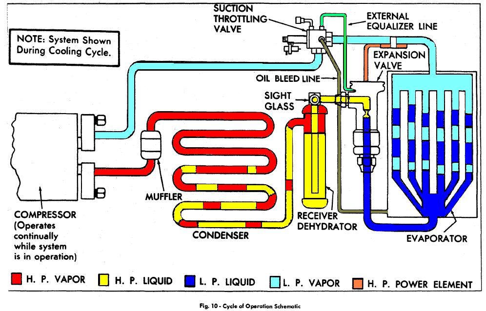
As a reference, here's the A/C system diagram from the 65 Corvette shop manual, which I colorized to help me better understand the details of the closed system. The "flow" of the system is counterclockwise.
05-07-2012, 01:34 PM
#49
Team Owner


Member Since: Oct 2000
Location: Washington Michigan
Posts: 38,899
Received 1,857 Likes
on
1,100 Posts

Thanks Larry and Jeff - The picture of how this all works is becoming clearer.I need to check the things you mentioned. Larry - concerning the fuse - I agree that the CSM is correct - I work in the electrical supply business and have never seen a small fuse of the size that would fit in the fuseholder that burned that was greater than 30 amps.
Thanks to both of you again - I'll keep you posted as I progress.
Tim
Thanks to both of you again - I'll keep you posted as I progress.
Tim
 05-10-2012, 06:26 PM
#50
Racer
Thread Starter
Member Since: May 2006
Location: Fairfield County Connecticut
Posts: 364
Likes: 0
Received 0 Likes
on
0 Posts
Thanks John and Jeff and Larry all all others who helped me understand the AC system. It has become clear to me that the only way to get this system working the way the General designed it is to remove the heater box and it's related components, test the vacuum switch and water valve and I believe I will probably find that the rubber weatherstripping on the various doors in the heater/ac box need replacing. As I now have another more pressing electrical project going on my other 64 that needs immediate attention, I do not want to have 2 cars off the road at the same time, so I will be suspending this project to complete the other. I will resurrect this thread at a later date - possibly not until the fall, when I won't mind having this car tied up.
Thanks again fellas and we'll pick this up soon.
Tim
Thanks again fellas and we'll pick this up soon.
Tim
05-10-2012, 06:35 PM
#51
Burning Brakes

 05-10-2012, 06:45 PM
#52
Tech Contributor
you do not need to remove the heater to test or replace the switch or valve.
05-11-2012, 09:33 AM
#54
Race Director
 Removing the heater box is not a job for the timid on these AC cars.........but if you do this job/rebuild, you should have a first class system for the rest of your driving days.
 Recommend DR REBUILD for your gasket/rebuild kit.
Larry