When you click on links to various merchants on this site and make a purchase, this can result in this site earning a commission. Affiliate programs and affiliations include, but are not limited to, the eBay Partner Network.
The seller Corvette-Stop is very negotiable; especially if you're a repeat customer. I never offer them more than 2/3 of what they ask and sometimes that does it and sometimes there is a bit more negotiation. I've never paid a BIN to them for a part.
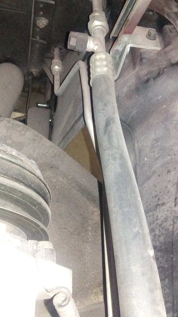
Do I have this drier plumbed correctly? The VA schematic seems to clearly show the IN side of the drier (right side in the picture with IN embossed) routing to the bottom of the condenser and the out side running along the inner fender to the evaporator. A friend sent me a picture of his installation that has been in operation for a year with the IN side pointing left and going to the evaporator.
The safety switch for the drier can be mounted from either side
Looks correct. Remove the masking tape thats covering the sight glass window on the top. Bill
Thanks Bill. One change from my last post. There is a plug in the drier on both sides so the safety switch can be mounted no matter which direction the dried is turned.
Thanks Bill. One change from my last post. There is a plug in the drier on both sides so the safety switch can be mounted no matter which direction the dried is turned.
You're dryer is correct. Flows high pressure from compressor into top of condenser and out the bottom, thru the dryer and then to the evaporator. Bill
I've had the condenser in and out four times today trying to get the two refrigerant line to clear the hood and hood prop. I've moved it left, right, up, down and repositioned the drier. My fear is that one or the other is going to get crushed when the hood closes. There is lots of adjustment but I just haven't hit the correct combination. It certainly wasn't the one called out in the instructions. Could someone(s) post pictures in that area so I can see what other installations look like
I've had the condenser in and out four times today trying to get the two refrigerant line to clear the hood and hood prop. I've moved it left, right, up, down and repositioned the drier. My fear is that one or the other is going to get crushed when the hood closes. There is lots of adjustment but I just haven't hit the correct combination. It certainly wasn't the one called out in the instructions. Could someone(s) post pictures in that area so I can see what other installations look like
You have them in the correct location. One line hugs the inner fender lip and the larger line routes to the engine side of the hood hinge. That is exactly how mine are routed. There is enough room, you won't crush them. I'll take some pics of mine a little later if you still need them.
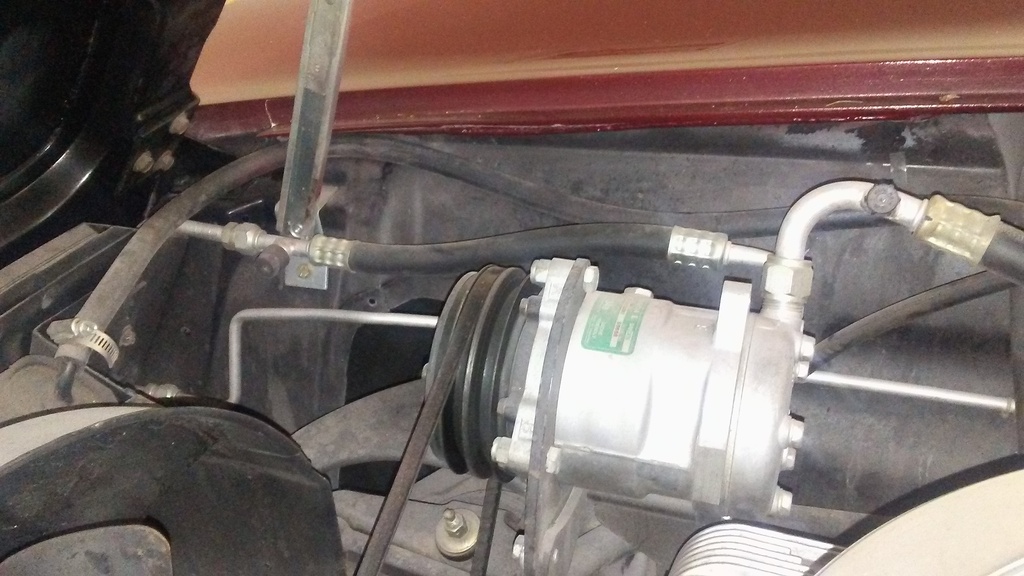
I believe that my VA system in my '66 may be the older version (one of the lines are a flexible type) but this may give you an idea on routing. The hood support does not experience any interference.
Ray (I will clean that ratty engine compartment next weekend, I swear)
Question 1: my heater hose from the water pump is 3/4" and the hose from the intake manifold is 5/8". The VA evaporator has two 5/8" heater fittings. How do I step down from 3/4" to 5/8"?
Question 2: In the instructions for installing the firewall cover plate it states, "use seam sealer to fill gap between cover & lip in firewall before painting". What is seam sealer?
Bonus question 3: Am I suppose to be painting all these covers and compressor brackets (which I have not been doing)?
You have to replace the 3/4" fitting with a 5/8", any auto store has it. I didn't paint my brackets but, I think it will look better. After a while, those raw steel brackets will rust.
1. The options (a Gates special hose or a reducer) are cited in the instructions (attached)...
2. The instructions say silicone sealer, a black RTV is fine.
3. My brackets were black when I got them IIRC, but paint them IMO.
NOTE: I eventually ordered the brackets for a regular, factory A/C alternator setup. They aren't so 'shade tree mechanic' looking...
Seam sealer can be purchased in a standard caulking tube from most parts stores. Just fill the gap and smooth it out with your finger and paint after it dries.
All of the Brackets should be painted to prevent rust.
Mark
Thanks to all for the advice. This is going painfully slow. Not because It's difficult but because I'm not able to work on it often. I'm about to get to the hard part
Would anyone share pictures of how you ran the lower heater hose from the firewall to the intake manifold. Especially where you placed the Gen IV heater control valve. I'm contemplating mounting the valve parallel to the firewall and then have a 90 degree elbow going around the corner of the battery then to the intake. I've read that the control valve tends to melt (or at least malfunction if it get close to the exhaust manifold. I'm nervous about cutting the hose (you can never make it longer) until I am certain of the route and control valve location
The heater control valve doesn't melt because of the heat from the manifold. It's a flawed design. I'm on my 4th one. You probably have the new and improved version. Two of my failures were that design.
So, put it somewhere that you can get to easily. If/when it fails, just give VA a call. They'll replace it with no questions asked.
After a short hiatus I am trying to finish this install up and the wiring is killin' me. First wiring question;
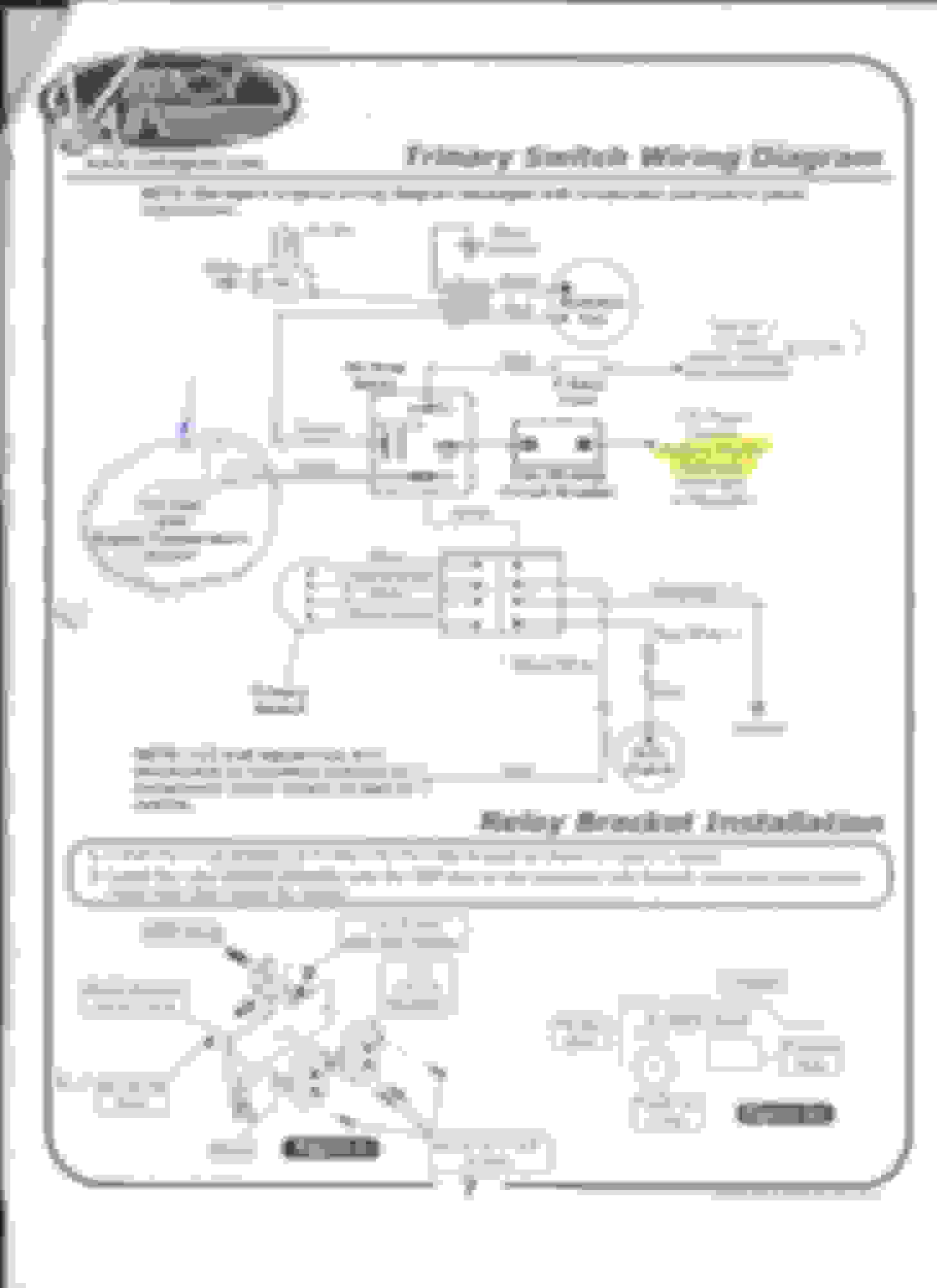
I have a Vintage Air auxiliary fan with a trinary switch. The wiring diagram for this switch calls for the white wire from the 30A relay to go to the "engine temperature sensor". Is that my temperature sending unit on the intake manifold? If so, how does the fan interpret the analog signal to know when to turn the fan on and off? If not, what and where is the "engine temperature sensor"?
I started the car tonight for the first time since I started this project and tested out the heater. The fan works as it should and I can redirect the air flow to whichever vent I choose. There is no refrigerant in the system and no belt on the compressor. The auxiliary fan did not operate when the engine came up to normal temperature, which I would think is correct without the AC running. I cut the engine off and everything stopped as it should. Then I turned the key to the accessory position and the auxiliary fan started running and continued running until I turned the key off. I am using the brown wire from the wiper motor as the "key on" power source in the trinary switch wiring diagram below. What do I have wired wrong?
UPDATE: I just ordered an "engine temperature sensor" from Vintage Air designed to come on at 190 degrees (I would have thought this would come in the package with the fan). Any recommendations on where to mount this second temperature probe?
 06-28-2017, 08:35 PM