Cam centerline question
 12-04-2017, 11:14 PM
#1
Drifting

Thread Starter


There are 2 ways to measure this. (maybe a third) I can go by I & E opening and closing points, then find the two centers, subtract and divide by 2 - OR I can find the I & E points of max lift, subtract and divide by 2.
My cam has very gentle opening and closing ramps (especially the closing side) so the opening and closing points get stretched out a lot. I'm afraid that won't be a "real life" centerline if calculated that way. Due to the late closing, I get 16deg retarded on the cam centerline.
IF I use the max lift points, I get 5deg retarded. OR............I could use opening and closing at say, .050" lobe lift.
Which would be the best "real world" way to know how to predict what rpm the cam makes its torque? Do the beginning of the ramps really have that much to do with it? I think their purpose is to just take the shock out of the lifter acceleration.
Thanks
Verne
notice the slow ramps.
Crower_Cam profile.pdf
 12-05-2017, 11:32 AM
#2
Race Director


Member Since: May 2000
Location: Redondo Beach USA
Posts: 12,487
Received 1,974 Likes
on
1,188 Posts

I don't understand what you're trying to do... measure lobe separation angle? Inlet Point of maximum lift, which defines how the cam is indexed to the crank?
Many cam lobes are asymmetrical, but it's tough to know how much, which can make measuring indexing tricky because it must be done on the portion of the lobe that is symmetrical.
LSA is fixed, should be stated on the cam card, and cannot be changed.
Indexing may be changed relative to how the cam is ground by using an adjustable timing set.
Advance and retard has to be stated relative to some reference point and that is the as ground inlet point of maximum lift. "Centerline" is a misused term because if the lobe is asymmetrical, the "centerline" of the lobe does not correspond to the POML.
For example, if the inlet POML is speced at 110 deg. ATC, then advancing, say, four degrees means you move it to 106 deg. ATC and retarding the same amount moves the POML to 114 deg. ATC.
If the lobe is asymmetrical you can usually get an accurate indexing POML by recording the crank angle at about .100" below max lobe lift on both the inlet and closing flanks, then compute the average, which is the POML. The most asymmetrical OE lobe is the one used on SHP big blocks and the inlet side of the LT-1 cam. Gross lobe lift is .306" and it's asymmetric below about .166" lobe lift, so the average of the crank angles at .200" lift on the opening and closing flanks should give you an accurate POML.
LSA, IPOML, and EPOML have a simple relationship.
LSA = (IPOML, deg. ATC +EPOML, deg. BTC)/2
So once you know any two of the parameters, you can compute the third.
Maximum torque and power engine speeds depend on a lot more than valve timing, and the only way to get a reasonable estimate is to use a simulation program with an accurate model of the engine configuration.
It's tough to see at a glance the true dynamics of this cam. The GM drawings list lobe lift, in inches, to five decimal places every cam degree, and I set up an Excel program to compute velocity, acceleration, and jerk using the drawing data.
The graph you posted appears to be mechanical lifter cam, but it's not sufficiently granular to tell for sure. If so, the portions that you call "slow" are the constant velocity clearance ramps. For reference, the velocity of the clearance ramps for the GM lobe I referenced above is .000400 inches per cam degree on the opening side and .000340 inches per cam degree on the closing side.
Duke
Last edited by SWCDuke; 12-05-2017 at 11:38 AM.
12-05-2017, 01:42 PM
#3
Drifting
Thread Starter
I was just looking for the most accurate way of finding where the cam is in relation to the crank; if its advanced or retarded. There are several lobe lift points where crank degrees can be measured and I was looking for the best way to do it so the result will mean something I can rely on when making the decision where I want to index the cam.
The actual lobe centerlines are waaaay off from the points of max lift due to the soft ramps.
I've been advised to use .050" lobe lift (opening & closing) for both I & E, and then compute the centers relative to the crank at zero. I have the lift data, so I can compare that to the 5deg retard I got using the max lift points.
This is a solid lifter cam that appears to have a 5deg retard built into it. Right now I have the crank gear in the 5deg advanced slot and it appears to be straight up. The cam card is from 1965 and doesn't have much information on it. Lord knows what lobe lift they used to compute duration (which is spec'd at 310deg); probably around .006"
Verne
Last edited by W Guy; 12-05-2017 at 01:43 PM.
12-05-2017, 04:01 PM
#4
Team Owner

Member Since: Nov 2005
Location: Beach & High Desert Southern California
Posts: 25,498
Received 2,339 Likes
on
890 Posts

I was just looking for the most accurate way of finding where the cam is in relation to the crank; if its advanced or retarded. There are several lobe lift points where crank degrees can be measured and I was looking for the best way to do it so the result will mean something I can rely on when making the decision where I want to index the cam.
The actual lobe centerlines are waaaay off from the points of max lift due to the soft ramps.
I've been advised to use .050" lobe lift (opening & closing) for both I & E, and then compute the centers relative to the crank at zero. I have the lift data, so I can compare that to the 5deg retard I got using the max lift points.
This is a solid lifter cam that appears to have a 5deg retard built into it. Right now I have the crank gear in the 5deg advanced slot and it appears to be straight up. The cam card is from 1965 and doesn't have much information on it. Lord knows what lobe lift they used to compute duration (which is spec'd at 310deg); probably around .006"
Verne
The actual lobe centerlines are waaaay off from the points of max lift due to the soft ramps.
I've been advised to use .050" lobe lift (opening & closing) for both I & E, and then compute the centers relative to the crank at zero. I have the lift data, so I can compare that to the 5deg retard I got using the max lift points.
This is a solid lifter cam that appears to have a 5deg retard built into it. Right now I have the crank gear in the 5deg advanced slot and it appears to be straight up. The cam card is from 1965 and doesn't have much information on it. Lord knows what lobe lift they used to compute duration (which is spec'd at 310deg); probably around .006"
Verne
Use .050" lobe lift at the opening point for the intake valve, and compare it to the Crower cam card specification for 0.050" lifter rise (or pushrod rise).
If the card says the Intake lifter 0.050" rise is at 15 deg BTDC, and you measure 10 deg BTDC with the timing marks at zero advance, then you can consider the cam keyway to be cut 5 deg retarded (or the timing gear keyway is offset cut).
You may measure the Exhaust lifter rise at 0.050" to verify the I/E lobe center angle.
You have to trust the cam grinder set the balance of the lobe & lift ramps based on the lifter rise lobe profile at 0.050".
Grinders use lifter rise profile at 0.050 for a reference because the lifter acceleration and resulting lifter/lobe contact force is a targeted value to balance performance and wear, and is predictable and deterministic on the typical constant velocity lobe profile. The lifter fall profile is where some cam grinders get creative with different spring and valve train mass recommendations to prevent valve float at higher rpm.
The summary point is to trust the lifter rise ramp measurements (valve opening position) over the lifter fall ramp measurements (valve close measurements).

The following users liked this post:
W Guy (12-05-2017)
12-07-2017, 11:15 PM
#5
Le Mans Master

Member Since: Oct 2002
Location: Las Vegas - Just stop perpetuating myths please.
Posts: 7,098
Received 373 Likes
on
356 Posts
Well I tried to answer this last night but my WIFI/router quit just as I hit the post button. Hope this is not to late to help but I'll try again.
I read of owners having problems with this measurement quite a bit. Maybe its a practice from the days of all symmetric lobe cams. Or maybe there are plenty enough cam cards that reflect the lobe center as at the halfway distance in degrees between open and closed specs or maybe 0.050" lift points. Who knows but it gets used a lot that way.
When I look for max/peak lift of the lobe I use a point/distance down from the max lift on each side - usually 0.050". I see SWD mentioned using 0.100" down from the max lift and I doubt anyone would measure 1 degree difference in accuracy between them. I maybe guessing here but I will say the difference at the top of the lobe whether symmetric or asymmetric would be un-measurable. And since you can already measure accurately the distance in degrees from the 0.050" lift points then measuring down the cam lobe will be much easier since your only looking at something like 10 degrees or less and this should reduce your error greatly. You could easily measure the max lift at both 0.050" and 0.100" down from max lift and compare them for your own reinforcement.
Yeh, so what I'm saying is to measure max lift of a lobe set your dial indicator up such that you read the degree wheel at the same point on both sides of max lift. You don't have to zero the dial indicator at max lift at all! You only have to watch for the same 0.050" change on both side of max lift and note the degree wheel readings (or use 0.100" or whatever but keep it small.).
Hope this helps.
12-08-2017, 10:26 AM
#6
Race Director
Member Since: May 2000
Location: Redondo Beach USA
Posts: 12,487
Received 1,974 Likes
on
1,188 Posts
You'll get better accuracy if you measure on a part of the lobe that is both symmetrical and high velocity. That's why I recommend .100" below max lift because velocity is higher than at .050" below max lift, and most asymmetrical lobes will still be on the symmetrical portion at .100" below max lift.
As with any procedure, measuring POML requires a little experience to get the most accurate results, so for the novice it might be a good idea to use both .050" and .100" below max lift and compare the results for consistency.
Duke
As with any procedure, measuring POML requires a little experience to get the most accurate results, so for the novice it might be a good idea to use both .050" and .100" below max lift and compare the results for consistency.
Duke
12-08-2017, 10:27 AM
#7
Drifting
Thread Starter
Thanks. That all makes sense. It seems the lobe centerline is almost a meaningless spec since it is based on the actual two points off the base circle which are spread out a lot and vary on both sides depending on the cam grinder's decision about lifter acceleration.
Thanks for taking the time to repost. I appreciate it.
Verne
Thanks for taking the time to repost. I appreciate it.
Verne
12-08-2017, 10:38 AM
#8
Drifting
Thread Starter
You'll get better accuracy if you measure on a part of the lobe that is both symmetrical and high velocity. That's why I recommend .100" below max lift because velocity is higher than at .050" below max lift, and most asymmetrical lobes will still be on the symmetrical portion at .100" below max lift.
As with any procedure, measuring POML requires a little experience to get the most accurate results, so for the novice it might be a good idea to use both .050" and .100" below max lift and compare the results for consistency.
Duke
As with any procedure, measuring POML requires a little experience to get the most accurate results, so for the novice it might be a good idea to use both .050" and .100" below max lift and compare the results for consistency.
Duke
After I get another issue cleared up with the timing gears, I'll set it up again and check it at both .050" and .100" and compare.
Verne
12-08-2017, 02:30 PM
#9
Race Director
Member Since: May 2000
Location: Redondo Beach USA
Posts: 12,487
Received 1,974 Likes
on
1,188 Posts
That's why I don't use the term "centerline", but Point of Maximum Lift, and you want to determine where it is relative to TDC. All this hotrod cam lingo like "centerline" and "straight up" that's been around since the dawn of aftermarket hot rod industry is vague and confusing, and maybe that's the way they want it.
A few years ago when I was working on cam designs I visited a small cam grinder in Southern California whose name I'm sure many of you would recognize. He had a couple of lobes that were in the ballpark in terms of duration, so I asked him if he could grind a cam using lobe "A" for the inlet side with the POML indexed at xxx degrees ATC, and lobe "B" on the exhaust side with a LSA of YYY.
He said he could not determine the "centerline" and I would have to "degree it in". He had no documentation other than the duration and max lift written on the lobe masters and could not tell me anything about the dynamics. I thanked him for his time and left the shop shaking my head and wondering how they had managed to stayed in business for so many decades.
I finally ended up using OE lobes because I wanted to maintain OE dynamics so OE valve springs could be used with confidence. I contacted Crane and found out they had the OE lobe masters I wanted and could grind the cam to my specified inlet POML and LSA. No problem, they understood exactly what I was saying and wanted. The new Parkerized cams were in the hands of the owners who were rebuilding their engines within a couple of weeks of ordering them, and the IPOML and LSA measured within a degree of spec.
It's not clear to me if it's clear to you that in order to determine the POML you record the crank angle at, say, .050" or .100" BELOW maximum lobe lift on both the opening and closing flank, not above the base circle, and the halfway point between the two crank angles you measure is the POML.
When measuring POML you don't need any data from the cam card other than to verify the POML you measure with an standard timing set is the same as what they probably list as "centerline" or to verify that the installed POML with and adjustable timing set is where you want it relative to the as-ground POML.
If you want to verify .050" inch duration, record crank angle at .050" above the base circle and compare to the cam card.
Duke
Last edited by SWCDuke; 12-08-2017 at 02:43 PM.
12-08-2017, 05:34 PM
#10
Drifting
Thread Starter
That's why I don't use the term "centerline", but Point of Maximum Lift, and you want to determine where it is relative to TDC. All this hotrod cam lingo like "centerline" and "straight up" that's been around since the dawn of aftermarket hot rod industry is vague and confusing, and maybe that's the way they want it.
A few years ago when I was working on cam designs I visited a small cam grinder in Southern California whose name I'm sure many of you would recognize. He had a couple of lobes that were in the ballpark in terms of duration, so I asked him if he could grind a cam using lobe "A" for the inlet side with the POML indexed at xxx degrees ATC, and lobe "B" on the exhaust side with a LSA of YYY.
He said he could not determine the "centerline" and I would have to "degree it in". He had no documentation other than the duration and max lift written on the lobe masters and could not tell me anything about the dynamics. I thanked him for his time and left the shop shaking my head and wondering how they had managed to stayed in business for so many decades.
I finally ended up using OE lobes because I wanted to maintain OE dynamics so OE valve springs could be used with confidence. I contacted Crane and found out they had the OE lobe masters I wanted and could grind the cam to my specified inlet POML and LSA. No problem, they understood exactly what I was saying and wanted. The new Parkerized cams were in the hands of the owners who were rebuilding their engines within a couple of weeks of ordering them, and the IPOML and LSA measured within a degree of spec.
It's not clear to me if it's clear to you that in order to determine the POML you record the crank angle at, say, .050" or .100" BELOW maximum lobe lift on both the opening and closing flank, not above the base circle, and the halfway point between the two crank angles you measure is the POML.
When measuring POML you don't need any data from the cam card other than to verify the POML you measure with an standard timing set is the same as what they probably list as "centerline" or to verify that the installed POML with and adjustable timing set is where you want it relative to the as-ground POML.
If you want to verify .050" inch duration, record crank angle at .050" above the base circle and compare to the cam card.
Duke
A few years ago when I was working on cam designs I visited a small cam grinder in Southern California whose name I'm sure many of you would recognize. He had a couple of lobes that were in the ballpark in terms of duration, so I asked him if he could grind a cam using lobe "A" for the inlet side with the POML indexed at xxx degrees ATC, and lobe "B" on the exhaust side with a LSA of YYY.
He said he could not determine the "centerline" and I would have to "degree it in". He had no documentation other than the duration and max lift written on the lobe masters and could not tell me anything about the dynamics. I thanked him for his time and left the shop shaking my head and wondering how they had managed to stayed in business for so many decades.
I finally ended up using OE lobes because I wanted to maintain OE dynamics so OE valve springs could be used with confidence. I contacted Crane and found out they had the OE lobe masters I wanted and could grind the cam to my specified inlet POML and LSA. No problem, they understood exactly what I was saying and wanted. The new Parkerized cams were in the hands of the owners who were rebuilding their engines within a couple of weeks of ordering them, and the IPOML and LSA measured within a degree of spec.
It's not clear to me if it's clear to you that in order to determine the POML you record the crank angle at, say, .050" or .100" BELOW maximum lobe lift on both the opening and closing flank, not above the base circle, and the halfway point between the two crank angles you measure is the POML.
When measuring POML you don't need any data from the cam card other than to verify the POML you measure with an standard timing set is the same as what they probably list as "centerline" or to verify that the installed POML with and adjustable timing set is where you want it relative to the as-ground POML.
If you want to verify .050" inch duration, record crank angle at .050" above the base circle and compare to the cam card.
Duke
Verne
12-08-2017, 06:59 PM
#11
Safety Car


Find TDC of #1 using a positive stop. Rotate both directions to the stop 1/2 way between is true TDC. Then find .050" before and after max lift one #1 intake lobe, count the degrees between the 2 points and divide. The distance in degrees from pistol TDC to intake lobe max lift is your number.
The following users liked this post:
W Guy (12-08-2017)
12-08-2017, 11:29 PM
#12
Safety Car
Lobe centerline really is not a useless term. often times cam grinders don't use the dowel as a datum point. They bump both sides of the rough lobe and start from there. So even though tons have put their cams in straight out of the box they have no idea where it is installed. You could buy 2 cams from the same place and they could vary 6 degrees easily. Most would never notice the difference. You would in a race engine and it changes piston to valve clearance. 6 degrees + would take .042" out of the intake clearance and add that much to the exhaust. So it does matter.
12-09-2017, 01:57 PM
#13
Drifting
Thread Starter
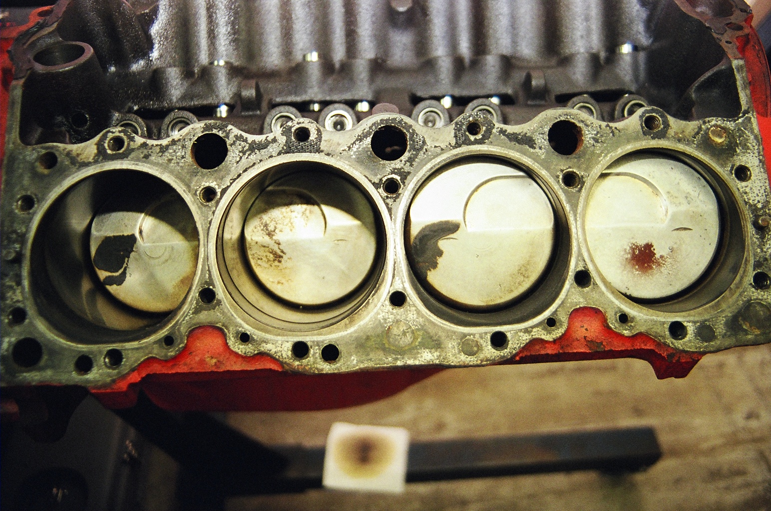
Understood. Here is evidence of a cam that was installed without checking it (before I bought the car). Notice the handshaking between the pistons and the exhaust valves.
Verne
Verne
12-09-2017, 06:26 PM
#14
Team Owner
Member Since: Nov 2005
Location: Beach & High Desert Southern California
Posts: 25,498
Received 2,339 Likes
on
890 Posts
Understood. Here is evidence of a cam that was installed without checking it (before I bought the car). Notice the handshaking between the pistons and the exhaust valves.
Verne
Attachment 48233551
Verne
Attachment 48233551
You need to know the piston crown to deck height (define it, and machine it into the design).
My 357 has flattop piston crowns 0.007 above the deck, with 0.045 head gaskets for a 0.038 quench. With 0.528 valve lift and 246 duration at 0.050 there is more than 0.060 clearance at 4 degrees cam advance or retard from the keyway cut. If I want to rock the torque peak up ~400 rpm I can retard the cam 4 degrees and swap the installed C3BX dual plane manifold for a Victor Jr single plane (both manifolds were port matched to the heads). The result should be about an 5% gain in peak torque and 8% in peak hp, but with the potential loss of the current Duntov 097' style cam feel and behaved off idle drive comfort (something if I reinstall the original RE 340hp/327 engine, and find a lighter car for the 357 to trap my son into a life of vehicle modification distraction).
Check the POML index point at the centerline from 0.050 on both sides of the POML, if you wish. Clay check for valve to piston interference advanced and retarded, if you have time and think you might change the cam indexing down the road and want assurance you do not create a problem.
12-09-2017, 10:38 PM
#15
Drifting
Thread Starter
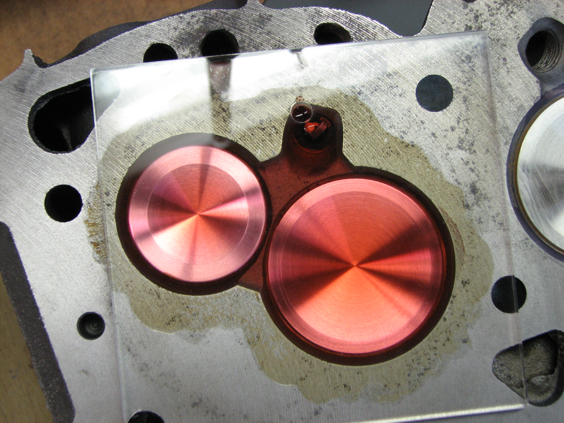
I do plan to use clay to check the clearance to the piston. One deck has been milled due to a sleeve that had to be installed, so I have different deck clearances which will require different thickness head gaskets. I have 4 to choose from and will select each one after calculating my desired compression ratio. I intend to use each gasket under each head with clay and check #1 & #2 once the gears are fixed and installed.
My pistons are in the hole because there is no combustion chamber in the head. (409). Only 13cc in the depressions around the valve heads and for the spark plug.
Verne
My pistons are in the hole because there is no combustion chamber in the head. (409). Only 13cc in the depressions around the valve heads and for the spark plug.
Verne
12-09-2017, 11:06 PM
#16
Le Mans Master
Member Since: Oct 2002
Location: Las Vegas - Just stop perpetuating myths please.
Posts: 7,098
Received 373 Likes
on
356 Posts
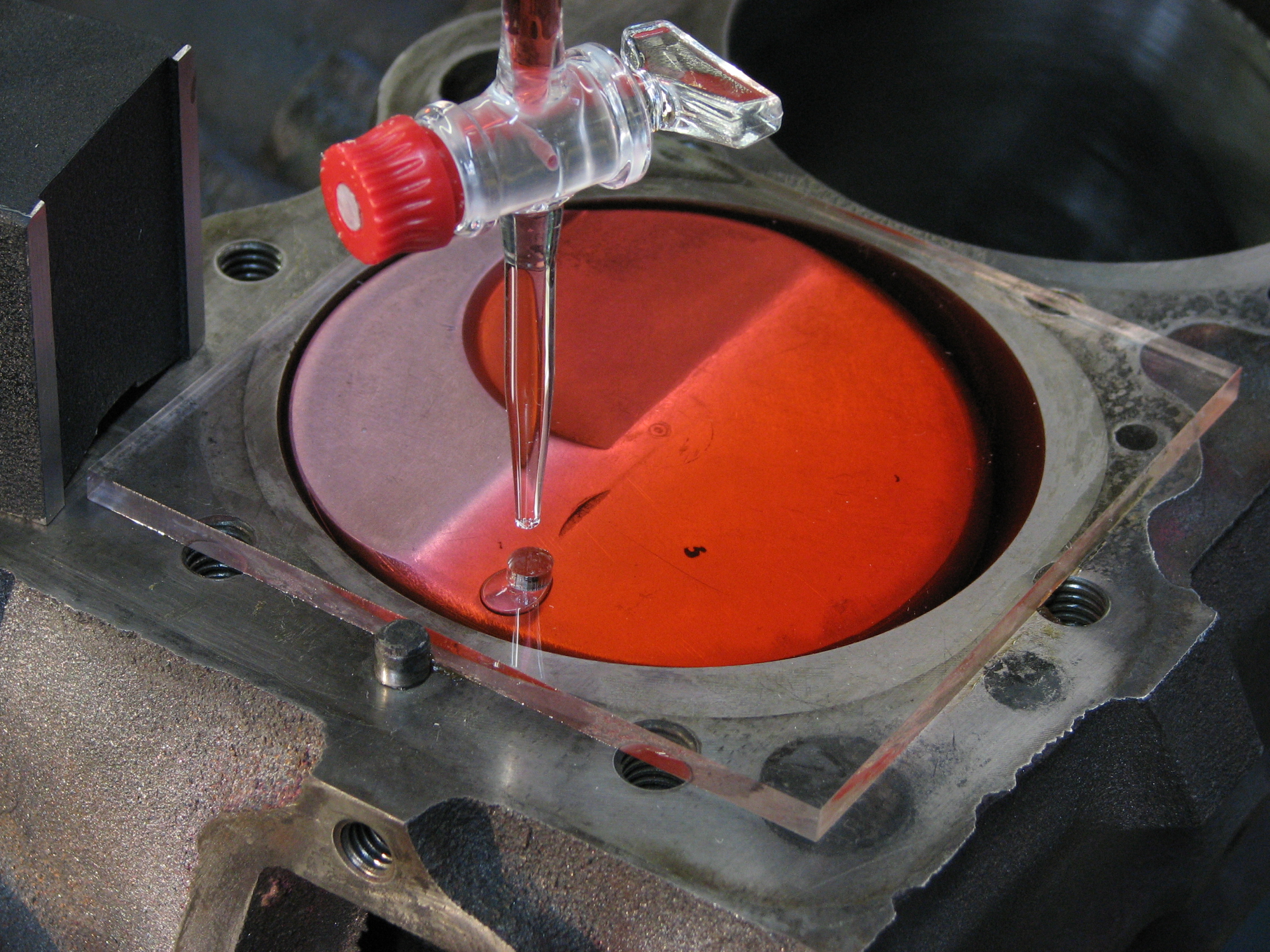
Nice work. It's cool to know what a 409 W motor head chamber volume really is. I'll bet countless owners call it zero volume.
I seem to have trouble with the last little bubble but have come to assume its less than 1cc. I just use a graduated cylinder rather than a burret and can't really measure less than 1cc (maybe 1/2cc but really a guess I think).
Thx for sharing and I hope you post your ICL results using the measure down method.
12-09-2017, 11:41 PM
#17
Melting Slicks

I do plan to use clay to check the clearance to the piston. One deck has been milled due to a sleeve that had to be installed, so I have different deck clearances which will require different thickness head gaskets. I have 4 to choose from and will select each one after calculating my desired compression ratio. I intend to use each gasket under each head with clay and check #1 & #2 once the gears are fixed and installed.
My pistons are in the hole because there is no combustion chamber in the head. (409). Only 13cc in the depressions around the valve heads and for the spark plug.
Verne
Attachment 48233715
Attachment 48233716
My pistons are in the hole because there is no combustion chamber in the head. (409). Only 13cc in the depressions around the valve heads and for the spark plug.
Verne
Attachment 48233715
Attachment 48233716
The following users liked this post:
W Guy (12-10-2017)
12-10-2017, 03:17 PM
#18
Drifting
Thread Starter
Nice work. It's cool to know what a 409 W motor head chamber volume really is. I'll bet countless owners call it zero volume.
I seem to have trouble with the last little bubble but have come to assume its less than 1cc. I just use a graduated cylinder rather than a burret and can't really measure less than 1cc (maybe 1/2cc but really a guess I think).
Thx for sharing and I hope you post your ICL results using the measure down method.
I seem to have trouble with the last little bubble but have come to assume its less than 1cc. I just use a graduated cylinder rather than a burret and can't really measure less than 1cc (maybe 1/2cc but really a guess I think).
Thx for sharing and I hope you post your ICL results using the measure down method.
I'll try to remember to report the final readings. Right now I'm waiting for a piston swap and rebalance, along with some needed machining on the back of the cam gear (which is another long story I won't bother to get into). If anyone here ever intends to use a double roller gear set up on a 409, please contact me for some needed guidance.
409s also present another issue when calculating compression. All the formulas assume a round head gasket.
Verne
 12-10-2017, 04:01 PM
#19
Melting Slicks
Don't worry about the bubble in my photo. When it was full I recorded the reading. By the time I got the camera, a tiny bit had leaked by the ring.
I'll try to remember to report the final readings. Right now I'm waiting for a piston swap and rebalance, along with some needed machining on the back of the cam gear (which is another long story I won't bother to get into). If anyone here ever intends to use a double roller gear set up on a 409, please contact me for some needed guidance.
409s also present another issue when calculating compression. All the formulas assume a round head gasket.
Verne
Attachment 48233924
That may be difficult on a 409 motor though.
Last edited by Critter1; 12-10-2017 at 04:02 PM.
12-10-2017, 08:03 PM
#20
Team Owner
Member Since: Nov 2005
Location: Beach & High Desert Southern California
Posts: 25,498
Received 2,339 Likes
on
890 Posts
Excellent photos of the 409 piston and chamber (or lack of chamber).
Few people take the time and effort to make the W-series engines run their best.
Post updates on the project so we may follow along.
Few people take the time and effort to make the W-series engines run their best.
Post updates on the project so we may follow along.
The following users liked this post:
W Guy (12-10-2017)