C1 & C2 Corvettes General C1 Corvette & C2 Corvette Discussion, Technical Info, Performance Upgrades, Project Builds, Restorations

[C2] Passenger Side Dash Pad

Thread Tools
 
Search this Thread
 
Old 03-17-2019, 04:52 PM
  #41  
MOXIE62
Safety Car
 
MOXIE62's Avatar
 
Member Since: Aug 2011
Posts: 3,573
Received 333 Likes on 276 Posts

Default

Don't know if you are going for show or street but this is a perfect time to clean all that dust, glue insulation or replace. You are breathing all that when driving close car. Also remove heater box, clean paint and check heater coil and install new gaskets. The flapper door inside heater box is the first to go and that is what seals out heat from coil heat. There is no seal at outlet.
The following users liked this post:
59BlueSilver (03-17-2019)
Old 03-18-2019, 09:04 PM
  #42  
59BlueSilver
Safety Car

Thread Starter
 
59BlueSilver's Avatar
 
Member Since: Apr 2013
Location: Arlington TX
Posts: 4,833
Received 931 Likes on 533 Posts
2023 Restomod of the Year Finalist
2023 C1 of the Year Finalist - Unmodified

Default

Originally Posted by Frankie the Fink
Yes you could lube the wiper arm pivots and as I stated check your clutch pedal's side to side movement to see if there is a broken weld....perfect time to install LED dash bulbs ...if not at least swap in all new incandescent bulbs.

Add a bullet crimp connector on that dangerous, "always hot" orange glove box wire (female connector on the power/fuse side of course). Lube tach/speedo cable. If your windshield leaks - a good time to shoot a little sealant in the corners.. Make sure your wiring harness is good and fuse box is fine...

Check if the nylon bushing in your pedal support bracket are installed and in good shape, adjust your brake light switch if needed.. Make sure heater box sliders and fresh air vents operate easily. Make sure firewall insulation is good and tight to the bulkhead.

I don't know about yout heater/defroster question as I have Vintage Air A/C-heater-defroster.
Thanks for pointing out those things, Frankie. I checked the clutch/brake pedal, no broken welds. I need to squirt some oil on the nylon bushing but all looks okay. Need to bond insulation.
When I took out the glove box but couldn’t figure out how to take out the glove light, so I just cut the wire. What do you mean when you say add a “crimp connector”? Do you mean so it can be disconnected & reconnected?

Old 03-18-2019, 09:27 PM
  #43  
Frankie the Fink
Team Owner

 
Frankie the Fink's Avatar
 
Member Since: Aug 2007
Posts: 58,062
Received 7,082 Likes on 4,736 Posts
Army

Default

Originally Posted by 59BlueSilver
Thanks for pointing out those things, Frankie. I checked the clutch/brake pedal, no broken welds. I need to squirt some oil on the nylon bushing but all looks okay. Need to bond insulation.
When I took out the glove box but couldn’t figure out how to take out the glove light, so I just cut the wire. What do you mean when you say add a “crimp connector”? Do you mean so it can be disconnected & reconnected?
Yes, so you don't have a bare "hot" terminal hanging down and you don't have to mess with the fragile glove box light every time you work in that area..


The following users liked this post:
59BlueSilver (03-18-2019)
Old 03-19-2019, 02:06 PM
  #44  
59BlueSilver
Safety Car

Thread Starter
 
59BlueSilver's Avatar
 
Member Since: Apr 2013
Location: Arlington TX
Posts: 4,833
Received 931 Likes on 533 Posts
2023 Restomod of the Year Finalist
2023 C1 of the Year Finalist - Unmodified

Default

Now the radio panels. These panels only had one screw in front holding them in. I see a fastening point in the rear of the console which looks like it coordinates with the holes in the panels. I ordered radio panel support clips. Where and how do they attach? Don’t find them in the assy manual. Also, there is a square hole in the L/H panel that looks like something goes there, what please?


Old 03-19-2019, 02:36 PM
  #45  
Godholio
Melting Slicks
 
Godholio's Avatar
 
Member Since: Jun 2008
Location: Columbia, SC
Posts: 2,102
Received 25 Likes on 23 Posts

Default

That hole is for the power antenna switch. Not sure about the other question, I didn't notice anything like that (or at least I don't remember it) when I had these panels to rebuild my clock a few years back.
The following users liked this post:
59BlueSilver (03-19-2019)
Old 03-19-2019, 02:38 PM
  #46  
MOXIE62
Safety Car
 
MOXIE62's Avatar
 
Member Since: Aug 2011
Posts: 3,573
Received 333 Likes on 276 Posts

Default

Don't know what year car you have but a 63 has 2 holes in the front, as shown in picture and 1 hole in rear that fastens to the heater output. There are no holes in bottom as the horse shoe molding holds

bottom in place.
Old 03-19-2019, 08:18 PM
  #47  
59BlueSilver
Safety Car

Thread Starter
 
59BlueSilver's Avatar
 
Member Since: Apr 2013
Location: Arlington TX
Posts: 4,833
Received 931 Likes on 533 Posts
2023 Restomod of the Year Finalist
2023 C1 of the Year Finalist - Unmodified

Default

It’s a 65. Here is a pic of the panel support clips I ordered. Where do they go, or do they go?

Old 03-19-2019, 11:24 PM
  #48  
MOXIE62
Safety Car
 
MOXIE62's Avatar
 
Member Since: Aug 2011
Posts: 3,573
Received 333 Likes on 276 Posts

Default

If you are talking about panel clips, there are none for 63. If you are talking about clock, I do not know. Never had my clock out.
Old 03-19-2019, 11:37 PM
  #49  
buns
Safety Car
 
buns's Avatar
 
Member Since: Feb 2006
Posts: 4,142
Received 690 Likes on 537 Posts

Default

Radio side panel support clip at arrow.


The following users liked this post:
59BlueSilver (03-20-2019)
Old 03-19-2019, 11:40 PM
  #50  
59BlueSilver
Safety Car

Thread Starter
 
59BlueSilver's Avatar
 
Member Since: Apr 2013
Location: Arlington TX
Posts: 4,833
Received 931 Likes on 533 Posts
2023 Restomod of the Year Finalist
2023 C1 of the Year Finalist - Unmodified

Default

Originally Posted by MOXIE62
If you are talking about panel clips, there are none for 63. If you are talking about clock, I do not know. Never had my clock out.
No, it’s not the clock clips. All the suppliers list them as radio panel support clips and they only show them for 1964-67.
Old 03-20-2019, 04:47 AM
  #51  
Frankie the Fink
Team Owner

 
Frankie the Fink's Avatar
 
Member Since: Aug 2007
Posts: 58,062
Received 7,082 Likes on 4,736 Posts
Army

Default

Those are riveted in for 63 as part of the plate that also includes the threaded flat piece that secures the shifter console extensions...

The following users liked this post:
59BlueSilver (03-20-2019)
Old 03-20-2019, 06:55 PM
  #52  
59BlueSilver
Safety Car

Thread Starter
 
59BlueSilver's Avatar
 
Member Since: Apr 2013
Location: Arlington TX
Posts: 4,833
Received 931 Likes on 533 Posts
2023 Restomod of the Year Finalist
2023 C1 of the Year Finalist - Unmodified

Default

Today I worked on the steering rag joint while I'm waiting for parts. I replaced the parts based on photos from other cars, so I'm looking for verification that I've assembled this correctly. Also, does anyone know the torque valves of the bolts?

Before


After

Old 03-20-2019, 07:57 PM
  #53  
Frankie the Fink
Team Owner

 
Frankie the Fink's Avatar
 
Member Since: Aug 2007
Posts: 58,062
Received 7,082 Likes on 4,736 Posts
Army

Default

That’s not how you want the coupler positioned when the steering is centered.

The lower section saw cut should face straight up.

Last edited by Frankie the Fink; 03-20-2019 at 08:03 PM.
The following users liked this post:
59BlueSilver (03-20-2019)
Old 03-22-2019, 09:43 PM
  #54  
JohnZ
Team Owner

Support Corvetteforum!
 
JohnZ's Avatar
 
Member Since: Oct 2000
Location: Washington Michigan
Posts: 38,899
Received 1,857 Likes on 1,100 Posts

Default

Originally Posted by 59BlueSilver
Also, is there any kind of a seal between the defroster duct and heater? Big gap on mine.

NOPE. That gap is there by design intent; if the bottom of the duct is attached to (or just touching) the heater case, heater noise (vibration, "coolant gurgling", etc.) will be transmitted by the duct to the fiberglass instrument panel and amplified, and it can get really loud. Standard Chevy design practice has always been to isolate the defroster duct by not attaching it to the top of the heater case.
Old 03-22-2019, 11:47 PM
  #55  
59BlueSilver
Safety Car

Thread Starter
 
59BlueSilver's Avatar
 
Member Since: Apr 2013
Location: Arlington TX
Posts: 4,833
Received 931 Likes on 533 Posts
2023 Restomod of the Year Finalist
2023 C1 of the Year Finalist - Unmodified

Default

Originally Posted by JohnZ
NOPE. That gap is there by design intent; if the bottom of the duct is attached to (or just touching) the heater case, heater noise (vibration, "coolant gurgling", etc.) will be transmitted by the duct to the fiberglass instrument panel and amplified, and it can get really loud. Standard Chevy design practice has always been to isolate the defroster duct by not attaching it to the top of the heater case.
Good to know, makes sense. Thanks for the explanation, John!
Old 03-25-2019, 11:28 PM
  #56  
59BlueSilver
Safety Car

Thread Starter
 
59BlueSilver's Avatar
 
Member Since: Apr 2013
Location: Arlington TX
Posts: 4,833
Received 931 Likes on 533 Posts
2023 Restomod of the Year Finalist
2023 C1 of the Year Finalist - Unmodified

Default

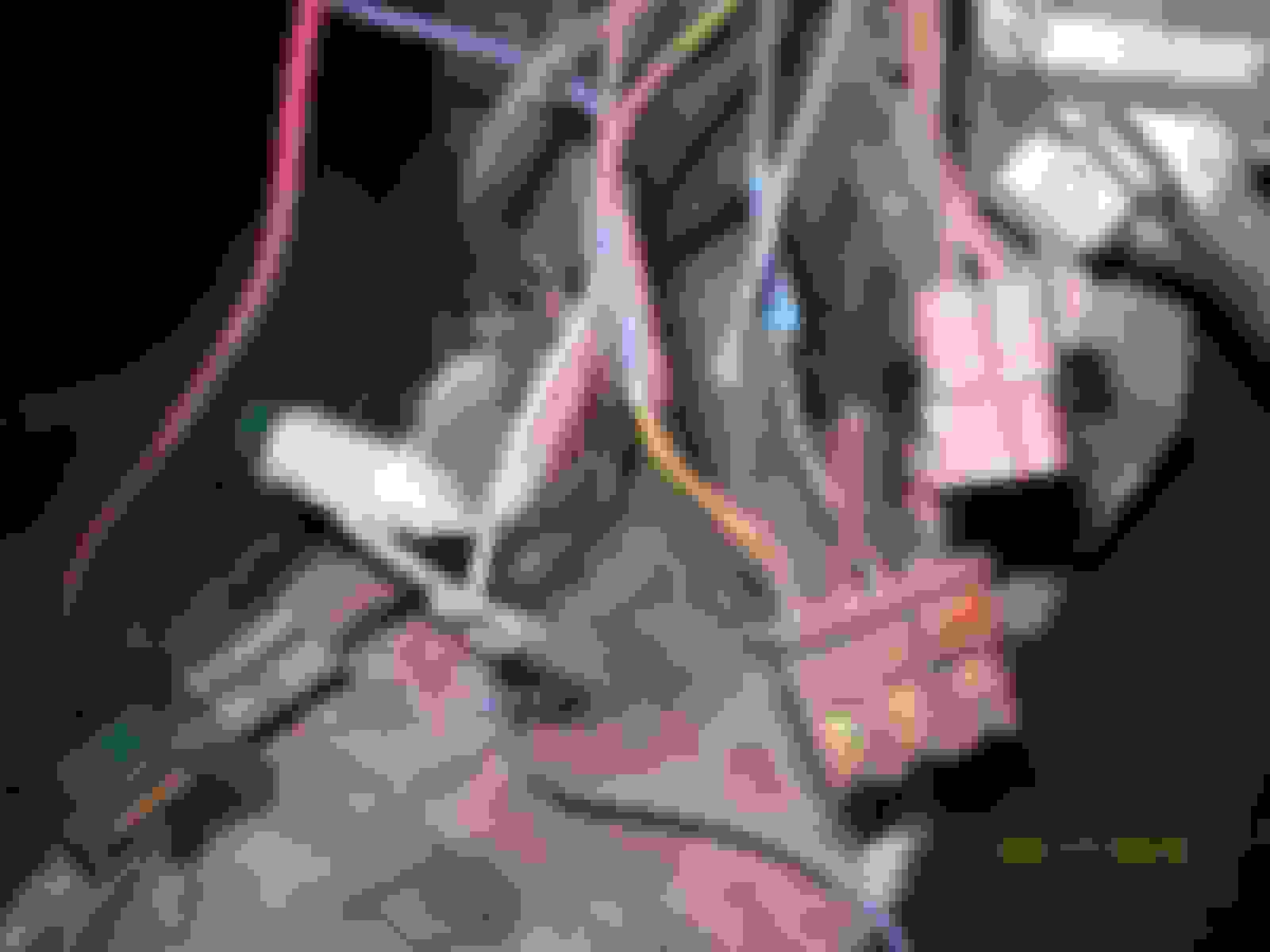
The bulk of my parts should arrive tomorrow, I hope, then I’ll start assembling everything. Behind the radio I came up with some wires I’m not sure about.

1. What does the green bulb with a clip do and where does it go?
2. The 3 or 4 connector with red overspray has some clipped wires. Is this for the radio? Are any of these wires speaker wires?
3. And the connector right above it?

Old 03-26-2019, 06:13 AM
  #57  
Frankie the Fink
Team Owner

 
Frankie the Fink's Avatar
 
Member Since: Aug 2007
Posts: 58,062
Received 7,082 Likes on 4,736 Posts
Army

Default

1. Radio bulb
2. Radio connector
3. Could be the speaker, I'd have to see a better picture...

I'd say that at some point somebody stuck in an aftermarket radio and just clipped the original ground/power wires off the connector shown and used them to power the new radio...

Get notified of new replies

To Passenger Side Dash Pad

Old 03-26-2019, 07:26 AM
  #58  
59BlueSilver
Safety Car

Thread Starter
 
59BlueSilver's Avatar
 
Member Since: Apr 2013
Location: Arlington TX
Posts: 4,833
Received 931 Likes on 533 Posts
2023 Restomod of the Year Finalist
2023 C1 of the Year Finalist - Unmodified

Default

Originally Posted by Frankie the Fink
1. Radio bulb
2. Radio connector
3. Could be the speaker, I'd have to see a better picture...

I'd say that at some point somebody stuck in an aftermarket radio and just clipped the original ground/power wires off the connector shown and used them to power the new radio...
Great, thanks Frankie, that’s exactly what happened. I intend to use the existing Retrosound radio but fix the wiring, kind of a mess. I’ll have to trace down the power & “memory” wires and then run my own speaker wires.
Old 03-26-2019, 09:23 PM
  #59  
buns
Safety Car
 
buns's Avatar
 
Member Since: Feb 2006
Posts: 4,142
Received 690 Likes on 537 Posts

Default

Actually, #1 is used to illuminate the heater control bezels. It mounts on the clock.
#3 is the connector for the power antenna.


The following users liked this post:
59BlueSilver (03-26-2019)
Old 03-26-2019, 10:03 PM
  #60  
Frankie the Fink
Team Owner

 
Frankie the Fink's Avatar
 
Member Since: Aug 2007
Posts: 58,062
Received 7,082 Likes on 4,736 Posts
Army

Default

OK then - my 63 doesn't have lighted heater controls, so my bad...


Quick Reply: [C2] Passenger Side Dash Pad


All times are GMT -4. The time now is 01:12 PM.