When you click on links to various merchants on this site and make a purchase, this can result in this site earning a commission. Affiliate programs and affiliations include, but are not limited to, the eBay Partner Network.
1966 Corvette smallblock
I realize that this is beating a dead horse but I found conflicting information regarding this.
I have a new Power Master 19100 Starter with only one wire on the solenoid.
This car has a ballast resistor.
I am going to install a diode between the engine side +12V large post to the wire that originally went to the "R" terminal.
So far so good.
1) One source says to put the diode band toward the starter post.
2) One source says to put the diode band toward the "R" wire that back feeds to the coil.
3) One source says to use a 3A 400V diode.
4) One source says to use a 10A 250V diode.
Please pick only two numbers from the above list.
Thank You
LOL
You want the banded end of the diode connected to the wire going to the coil (+) terminal.
I'd connect the non-banded end of the diode to the "S" terminal of the starter.
As to which diode, more current capability is better. However so is greater reverse bias Voltage capability. Of the two diodes you list, I'd go with the 3A, 450 V device.
Jim
Last edited by jim lockwood; Apr 12, 2019 at 10:28 AM.
You definitely want the banded end of the diode pointing at the coil.
Here's a simple explanation of current flow through a diode. An easy way to remember is the diode symbol, current flows with the arrow and not against the bar. The bar is the banded side.
You definitely want the banded end of the diode pointing at the coil.
Here's a simple explanation of current flow through a diode. An easy way to remember is the diode symbol, current flows with the arrow and not against the bar. The bar is the banded side.
I completely agree with Jim, including the third option that you omitted (what starter terminal do I connect the diode to).
In the old days, we talked about either electron flow or hole flow. This had to do with the direction of current flow. Today, the standard is electron flow meaning that current flows from - to +. The schematic symbol for a diode is an arrow with a line drawn across the tip. The band on the physical diode represents the line. Consider the arrow pointing towards the line to indicate the direction that current will not flow. By placing the band towards the - or non + side, current will flow when +12v is applied to the opposite side of the band. I’m sure this is more info than you wanted, so I will continue!
By placing the diode connected to the large +12v post on the starter, you will have +12v to the diode at all times. Not an issue if your points happen to be open when the engine stops turning. However, if the points are closed current will continue to flow draining your battery and perhaps damaging your coil. By using the S terminal, +12v will only be applied when the key is in the START position effectively bypassing the ballast resistor during cranking.
You definitely want the banded end of the diode pointing at the coil.
Here's a simple explanation of current flow through a diode. An easy way to remember is the diode symbol, current flows with the arrow and not against the bar. The bar is the banded side.
I don't disagree with the direction of the band, but current (electrons) flow against the arrow. DC current flow is negative to positive as the negatively charged electrons are moved toward the positive.
Semiconductor diode schematic symbol: Arrows indicate the direction of electron current flow.
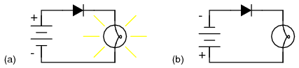
When placed in a simple battery-lamp circuit, the diode will either allow or prevent current through the lamp, depending on the polarity of the applied voltage. (Figure below)
Diode operation: (a) Current flow is permitted; the diode is forward biased. (b) Current flow is prohibited; the diode is reversed biased.
When the polarity of the battery is such that electrons are allowed to flow through the diode, the diode is said to be forward-biased. Conversely, when the battery is �backward� and the diode blocks current, the diode is said to be reverse-biased. A diode may be thought of as like a switch: �closed� when forward-biased and �open� when reverse-biased.
Oddly enough, the direction of the diode symbol�s �arrowhead� points against the direction of electron flow. This is because the diode symbol was invented by engineers, who predominantly use conventional flownotation in their schematics, showing current as a flow of charge from the positive (+) side of the voltage source to the negative (-). This convention holds true for all semiconductor symbols possessing �arrowheads:� the arrow points in the permitted direction of conventional flow, and against the permitted direction of electron flow.
Hey, remind me to tell you kids about the time we were able to electronically steer a radar lobe through a series of splitters and frequency phase shifters eliminating the need for any kind of mechanical rotation or fixed waveguide emitter positioning. It’s a hoot!
And then GG had to go and bring in PN junction theory!
I had to. My electronics training with schematics wouldn't stop poking at me when I read "current flows with the arrow". If you're following a diagram, you could end up with no current flow in your circuit. You guys are the experts on which way the band faces in this case, I've never connected a diode to a car starter.
Hey, remind me to tell you kids about the time we were able to electronically steer a radar lobe through a series of splitters and frequency phase shifters eliminating the need for any kind of mechanical rotation or fixed waveguide emitter positioning. It�s a hoot!
Hey, remind me to tell you kids about the time we were able to electronically steer a radar lobe through a series of splitters and frequency phase shifters eliminating the need for any kind of mechanical rotation or fixed waveguide emitter positioning. It�s a hoot!
From: Las Vegas - Just stop perpetuating myths please.
That wire with the diode to the coil boosts spark energy only for starting. With a more efficient starter that spins the motor faster the OP may not need that diode/wire/voltage boost. Even more so if the ignition has been upgraded.
Hey, remind me to tell you kids about the time we were able to electronically steer a radar lobe through a series of splitters and frequency phase shifters eliminating the need for any kind of mechanical rotation or fixed waveguide emitter positioning. It�s a hoot!
Sorry, it�s a slow day here at the ranch.
Then I won�t tell you about tracking Russian missile shots in Turkey in the 70s and when the computer lost lock I�d have to use a joystick to �paint� the sky trying to find it. If you slammed that 20� radar dish into the mechanical stops too hard the whole array could tumble down the mountain into the Black Sea. Those were the days.
Last edited by Frankie the Fink; Apr 12, 2019 at 12:31 PM.
From: Las Vegas - Just stop perpetuating myths please.
Yes it stops current flow in the wrong direction when the ignition key is not in start. But when the key is in start and the starter solenoid has picked up it passes current - and full battery voltage - in the correct direction to the coil bypassing the "ballast resistor" and it voltage drop.
Yes it stops current flow in the wrong direction when the ignition key is not in start. But when the key is in start and the starter solenoid has picked up it passes current - and full battery voltage - in the correct direction to the coil bypassing the "ballast resistor" and it voltage drop.
What did you think the wire/diode was for?
I know the theory, but I wouldn�t call that �boost�.
Heat is the enemy of all electronics. Diodes don't get a free pass. Use them in an environment which gets too hot and they will fail. Diodes rated for commercial use are specified for temperatures no higher than 70 C (about 158 F). An engine compartment can easily get this hot.
I would NOT mount the diode on the starter or, for that matter, anywhere in the engine bay.
My suggestion is that the OP install the diode in the passenger compartment and run wires from the diode, through the firewall, to the coil (+) terminal and to the starter "S" terminal.
Extra credit will be given if the OP splices into these two circuits at points behind the instrument cluster, thereby avoiding unsightly extra wires in the engine bay.
Designer Imagines A Corvette That Looks More Like a Corvette Than the Corvette
Slideshow: A Jaguar designer's personal project imagines what a modern front-engined Corvette might look like if Chevrolet revisited the golden age of the Stingray.