When you click on links to various merchants on this site and make a purchase, this can result in this site earning a commission. Affiliate programs and affiliations include, but are not limited to, the eBay Partner Network.
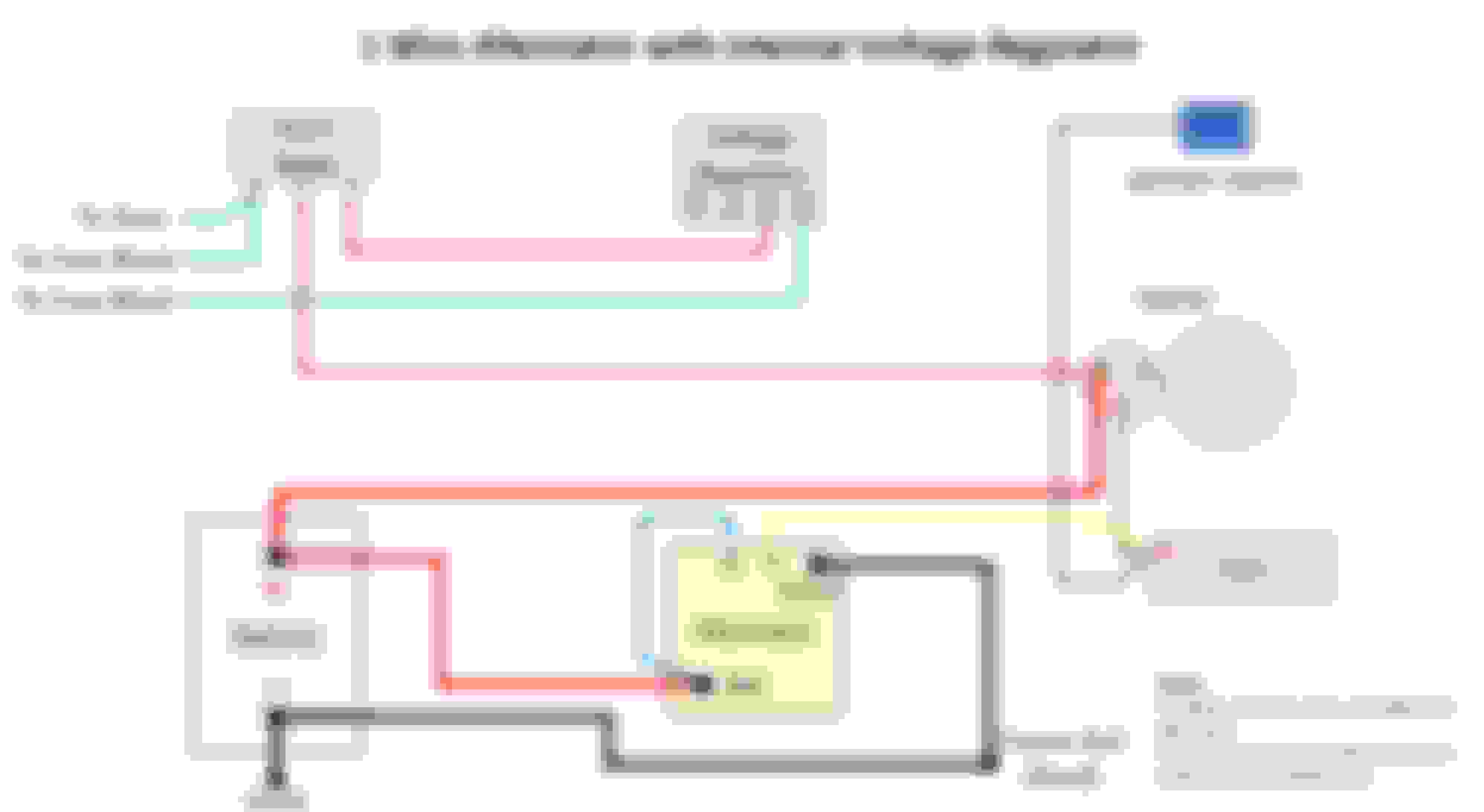
I am installing a Mechman alternator on my 64 coupe with a small block. The unit has an internal voltage regulator. The diagram below shows how the new alternator bypasses the voltage regulator. My problem is that lead 3 goes to the horn relay and lead 4 goes to the fuse block that powers the temperature sender, heater blower, and another lead goes to the battery terminal of the starter motor. What is the correct wiring for this new alternator, has anyone else done this conversion? This is a one wire but is ignition excited not self-excited, and should perform in the same fashion as a traditional 3-wire unit.
The diagram says "One Wire" but then shows a normal internally regulated alternator set up. A true "one wire" literally only has one wire, the heavy red wire that goes to the battery. The field trips when engine speed reaches 1200-1500 rpm. Your diagram is usually referred to as a "three wire" internally regulated alternator. To answer your question, if you want to avoid trying to remove wires from your harness just unplug the VR as Hemi said above.
The diagram says "One Wire" but then shows a normal internally regulated alternator set up. A true "one wire" literally only has one wire, the heavy red wire that goes to the battery. The field trips when engine speed reaches 1200-1500 rpm. Your diagram is usually referred to as a "three wire" internally regulated alternator. To answer your question, if you want to avoid trying to remove wires from your harness just unplug the VR as Hemi said above.
You're correct, it's a normal internally regulated alternator.
That diagram is not very helpful. Where's your ballast resistor? Where's the wire going from the starter up to the plus on the coil when you're in the start position? Also the horn wire isn't fused on a C2. does it say what kind of car that diagram is supposed to be for?
That diagram is not very helpful. Where's your ballast resistor? Where's the wire going from the starter up to the plus on the coil when you're in the start position? Also the horn wire isn't fused on a C2. does it say what kind of car that diagram is supposed to be for?
I did this drawing so it may not be complete. Ballast resistor was bypassed as I am using Pertronix ignition and it requires full 12V. Starter to coil positive is shown as purple wire going from R terminal of starter. I should have labeled the horn relay wire as going to a terminal block, I may be using the wrong terminology.
You're correct, it's a normal internally regulated alternator.
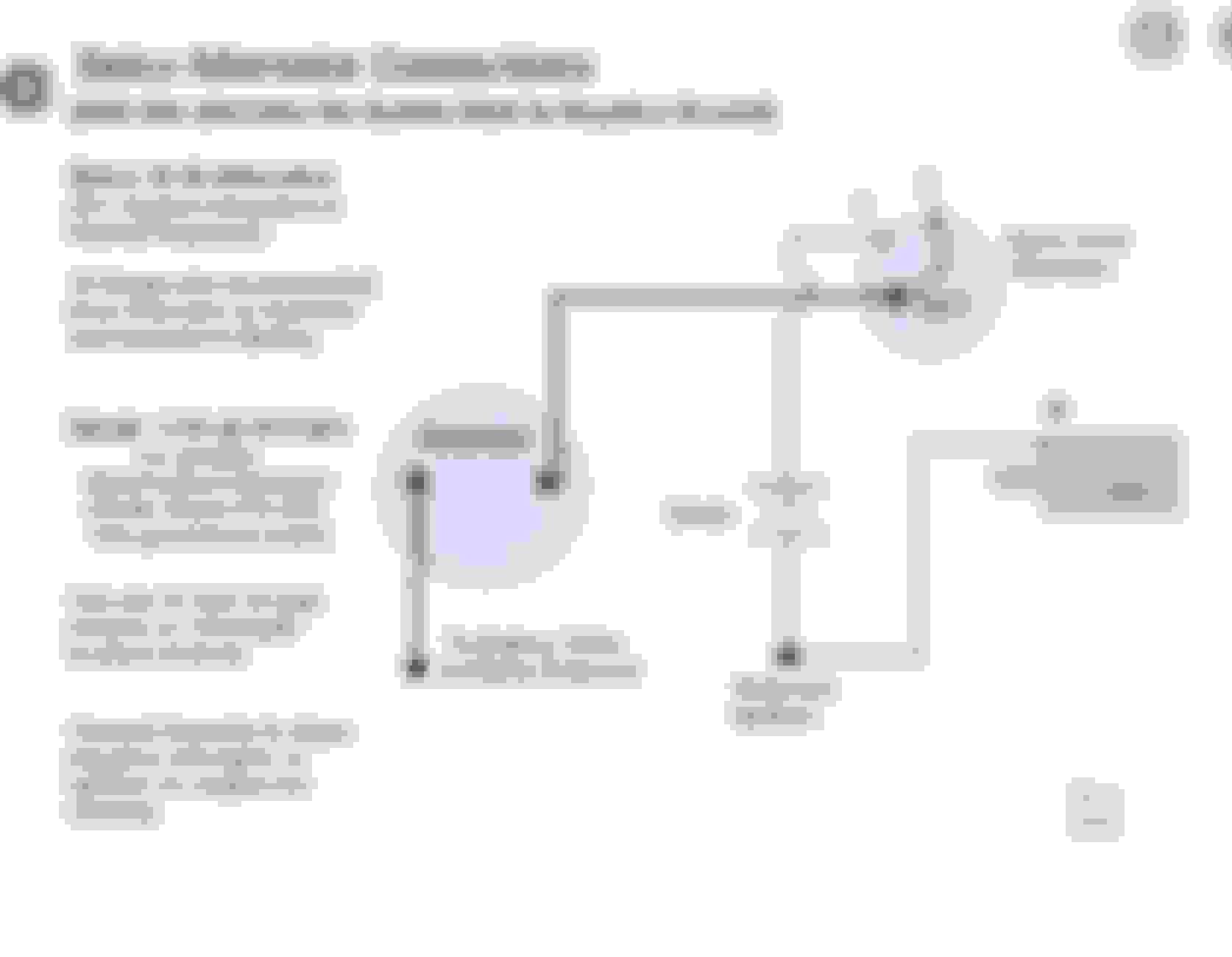
If that's the case (and you wire it like your schematic) then when shut off the alternator will back feed the coil and the engine won't shut off. You need a bulb, diode or resistor between ignition hot and terminal #1. Here is a good schematic to follow:
Edit: The wire going to #4 terminal on the regulator has an integrated resistor wire in the harness. That would be the one to use for the internal reg alternator #1 terminal.
Mike I was looking into this company also I liked the look & most of all everything I read on their product seemed positive are you getting the chrome or polished unit?
I�m curious do you or are you planning to run a/c?
Try & post a pic of your install would love to see it I�ve collecting brackets, ARP bolts & such for my future a/c install & thought this unit would look great with a polished a/c compressor on the opposing side of the engine.
Good Luck
Chalie
Just saw your post, sorry for the delay. I got the natural finish but will definitely post a pic of the install when done. Mechman's tech support says it's a simple install, I only need to connect to an ignition-switched 12V power source. I will confirm with Mechman to be sure but I assume that this unit may have an internal diode to shut it off when the ignition is switched off. Since the accessories will run without the regulator, I will just eliminate this from the circuit.
If that's the case (and you wire it like your schematic) then when shut off the alternator will back feed the coil and the engine won't shut off. You need a bulb, diode or resistor between ignition hot and terminal #1. Here is a good schematic to follow:
Edit: The wire going to #4 terminal on the regulator has an integrated resistor wire in the harness. That would be the one to use for the internal reg alternator #1 terminal.
I see. If I connect #1 alt. terminal where #4 voltage regulator currently goes, then I can eliminate the voltage regulator and the connection between #3 terminal of voltage regulator and the horn relay?
I see. If I connect #1 alt. terminal where #4 voltage regulator currently goes, then I can eliminate the voltage regulator and the connection between #3 terminal of voltage regulator and the horn relay?
For sure, that way you'll take advantage of the resistor wire of the #4.
Here is an update on the alternator installation. Output to battery still not connected pending finalization of other refurbishments, but the pictures show the general arrangement, based on 426Hemi's suggestion. Thank you! This is a shot of the alternator. It is a Mechman 170amp internally regulated unit. The output line is 4AWG fused going directly to the battery positive. Yellow wire is 12V input which previously went to terminal 4 of the voltage regulator. This shows a closeup of the 12V input to the alternator coming from terminal 4 of the connector to the voltage regulator, which was removed.
Slick upgrade.. You mentioned a FUSED output to the battery, I’m curious how you fused it could you share more on that. Thanks again for your follow up on this upgrade,
Chalie
I can’t tell in the picture, but you should run a heavy gauge ground to the alternator case when running a higher power alternator in a fiberglass bodied can.
Slick upgrade.. You mentioned a FUSED output to the battery, I�m curious how you fused it could you share more on that. Thanks again for your follow up on this upgrade,
Chalie
Yes, I bought an alternator installation kit from CE Auto Electric Supply (link below). They provide high end automotive electronics. This kit comes with the heavy gauge output wire that includes an integrated fuse holder. Very nice for the upgrade. The higher capacity alternator will be the basis for an overall wiring upgrade to support EFI and a new ignition system. I'm not a big stereo guy but I may update that as well.
Good looking alternator. I thought you were dealing with a Delco internal regulator alternator (Delco 10 & 12SI). The terminal 4 should still work though.
Side note, with the alternator connected directly to the battery, the stock "battery" gauge isn't going to show a charge. The alternator output wire (the big red one) would have to be hooked up to the horn relay for that to work.
 06-24-2020, 12:02 PM