When you click on links to various merchants on this site and make a purchase, this can result in this site earning a commission. Affiliate programs and affiliations include, but are not limited to, the eBay Partner Network.
The distributor is firing well now on manifold vacuum
I let it idle/revved it in the garage.....NO PROBLEMS....
I drove around the neighborhood 20mph NO PROBLEMS
I drove on the Blvd 30 mph..................NO PROBLEMS
I took it onto the highway....................
SPIT..........SPUTTER.........BACKFIRE THROUGH EXHAUST.....WILL NOT GO FASTER THAN 45 MPH
It limped back home
The FIRST thing that I noticed in the garage......the side pipe exhaust were SOLID BLACK WITH SOOT
I'm jussssssssssssssst about ready to slap a new Edelbrock carb (I have no idea how old this one is) on the engine since that's what the adapter on the quadrajet intake is set up for.
Before I do-dat.............anybody got any suggestions??????????
Are secondaries opening fully? Throttle blades slipping on shaft?
Don't know if this would cause backfire.
Tranny shifting o.k. .
Just for fun try a test run with no intake or air filters, sounds like it's starving for o2
Last edited by Calo69; 09-05-2015 at 11:10 PM.
Reason: Add
DoorGunner, I have used Hollies Spread Bore carbs and they are wonderful. The one on my 327 was about 35 years old! The new one on my ZZ4 has an electric choke.
The Edelbrock is a copy of an ancient Carter carb and people have trouble with them.
Lou.
Are secondaries opening fully? Throttle blades slipping on shaft?
Don't know if this would cause backfire.
Tranny shifting o.k. .
Just for fun try a test run with no intake or air filters, sounds like it's starving for o2
The primary and secondary throttle plates are tight on the shafts. The TH400 shifts fine, but will not downshift because of the sputtering @ 45 mph. I'll drive it tomorrow a mile or two with no air filters.
Originally Posted by loup68
DoorGunner, I have used Hollies Spread Bore carbs and they are wonderful. The one on my 327 was about 35 years old! The new one on my ZZ4 has an electric choke.
The Edelbrock is a copy of an ancient Carter carb and people have trouble with them.
Lou.
It's after midnight and I just made a new airhorn gasket because the original was falling apart. I'll start/adjust it in the morning.
I have a Holley 1850 (I added a spare electric choke to it) on my '34 street truck stock 350 cu.in. 700R4 drivetrain.
You are right about it being easy to install...I bolted it to the intake with an adapter plate/connected the fuel line, the 12v. wire to the choke, the throttle cable/started the truck and drove for about an hour......not ONE "hiccup"!
I have a 1980 carburetor that was rebuilt about 6 months ago. If you want it is yours just pay shipping. Maybe it'll help you out. I put a new 383 stroker with Edelbrock carburetor is the only reason I'm not using the Quadrajet.
I have a 1980 carburetor that was rebuilt about 6 months ago. If you want it is yours just pay shipping. Maybe it'll help you out. I put a new 383 stroker with Edelbrock carburetor is the only reason I'm not using the Quadrajet.
Thanks havesometo......I'm not giving up on this Edelbrock yet.
The new gasket helped with the idle air screw adjustment.....the engine never killed while turning either screw all the way in....now both screws are affecting the idle/engine-running with adjust ment.
Now for the highway news................
I reversed the problem..............yesterday the car wouldn't go faster than 45 mph without popping/sputtering through the exhaust.
TODAY...........the engine sputters and pops until it gets to 45.....
Yep.......about every six months it goes bizerk! I gutted it last winter/cleaned EVERY orifice forward and backwards/put a rebuild kit in it/it did great----------NOW BACK TO ZERO!
The dinky little Holley 600cfm on my '34 truck hasn't been touched in 8 years.....that 350 runs "like a scalded ape!"
I'm going to leave it alone a few days and do some other things to the car.
Sounds like you need to get rid of that Edelbrock, I had one on my 76 for about a week, took it off and sold the damn thing, just wasn't happy with it. I took a $50 loss on it but you live and learn, never again will I buy an Edelbrock carb...
Was looking into one awhile ago, found out they were one of the trickiest to tune.
Some advice I remember was to tune it like a 1405 more performance oriented set up.
Sounds like you need to get rid of that Edelbrock, I had one on my 76 for about a week, took it off and sold the damn thing, just wasn't happy with it. I took a $50 loss on it but you live and learn, never again will I buy an Edelbrock carb...
Originally Posted by Calo69
Was looking into one awhile ago, found out they were one of the trickiest to tune.
Some advice I remember was to tune it like a 1405 more performance oriented set up.
When it "feels like it" the carb makes the engine scream
When it doesn't "feel like it"......I'm the one screaming
What is aggravating....I could have restored the '76 "nose"/grill area of the car back to '68 looks with the week I've spent dealing with/thinking about/re-doing everything that I "re-did" !
Ohhhhhhh well......it's "all in fun"
92190
Last edited by doorgunner; 09-07-2015 at 12:37 AM.
PLEASE LOOK THROUGH THE COMPLETE POST IF YOU ARE CONSIDERING THIS MODIFICATION------I HAD TO MAKE A CHANGE TO MY PLANS MID-WAY WHEN IT CAME TIME TO FIT THE CHROME BUMPER AS IT CAME FROM THE FACTORY....I EITHER HAD TO MODIFY THE CHROME BUMPER OR GREATLY MODIFY THE NOSE OF THE CAR
***********SAMPLE REFERENCE PICS PROVIDED BY FORUM MEMBERS ARE INSERTED BETWEEN MY PICS*********
*****I am combining all future work on the grill area into this ONE POST so that it will be easy to see the steps and progression*****
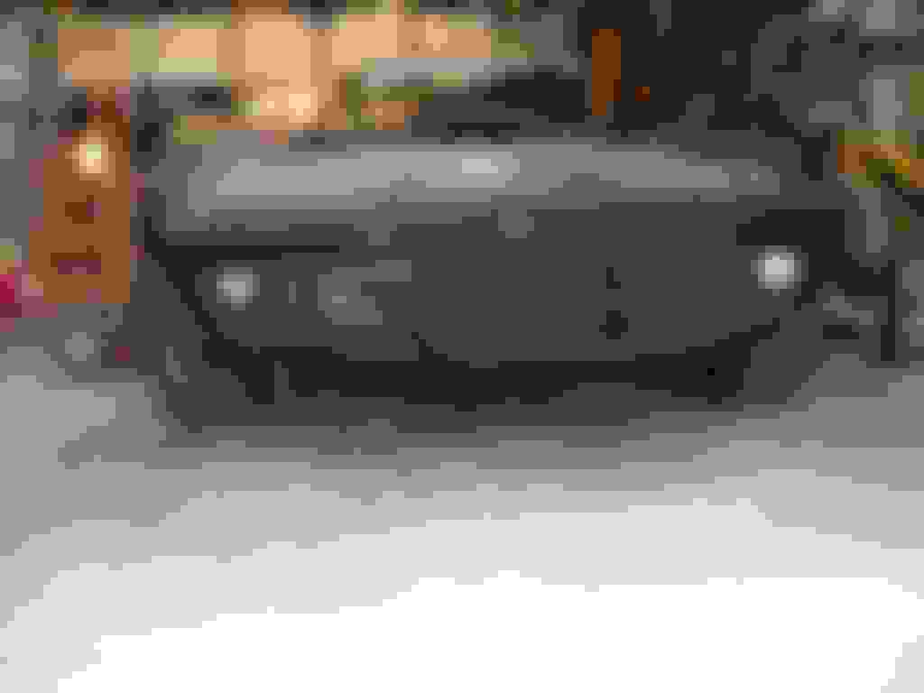
THIS IS THE LOOK I WILL TRY TO IMITATE................................. .........
Brace yourself.......it's scary..............
Here's the pricelist for the Conversion" (parts are not NOS/parts were bought "on sale"/it's a costly conversion, but necessary to me))
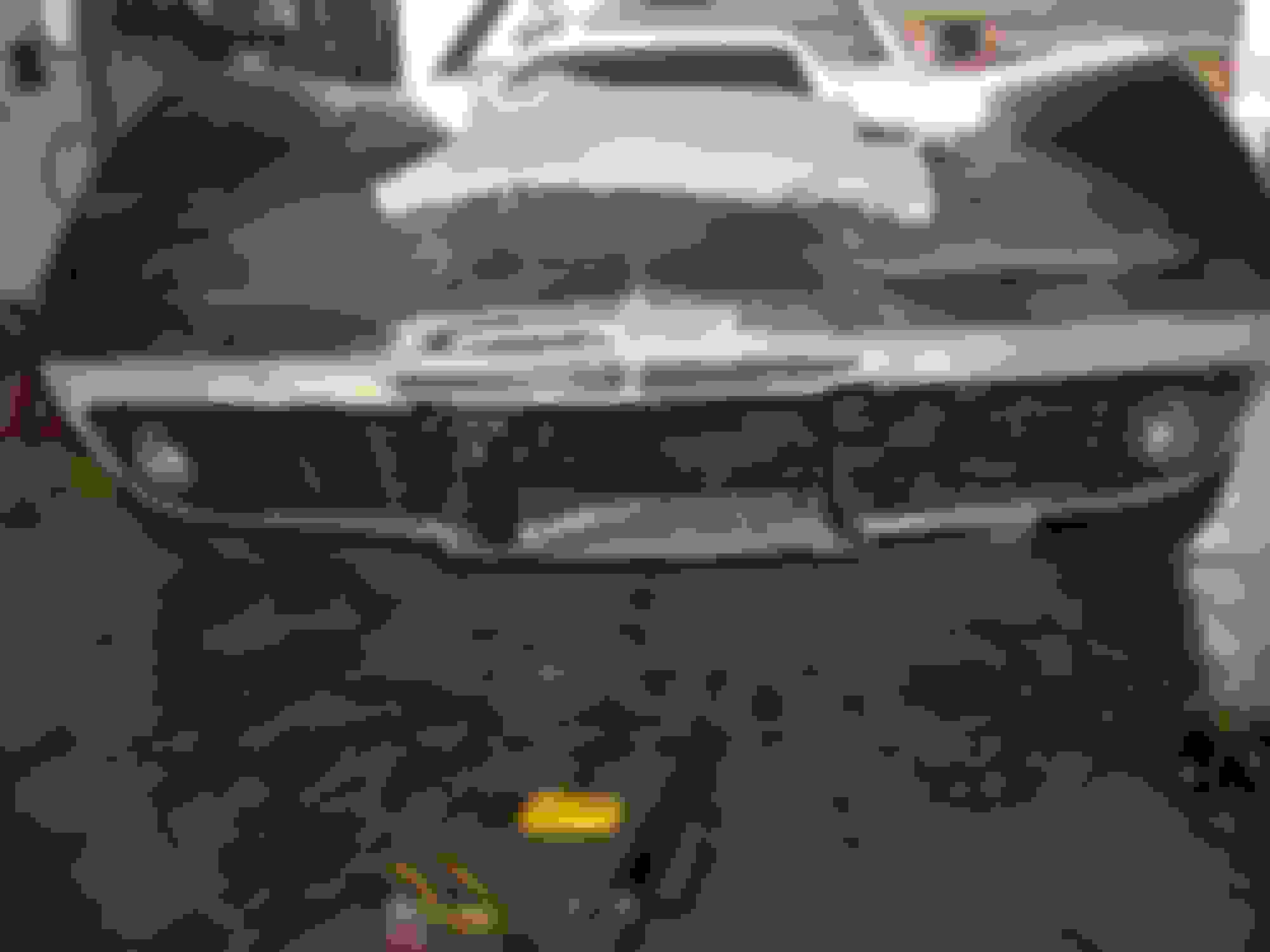
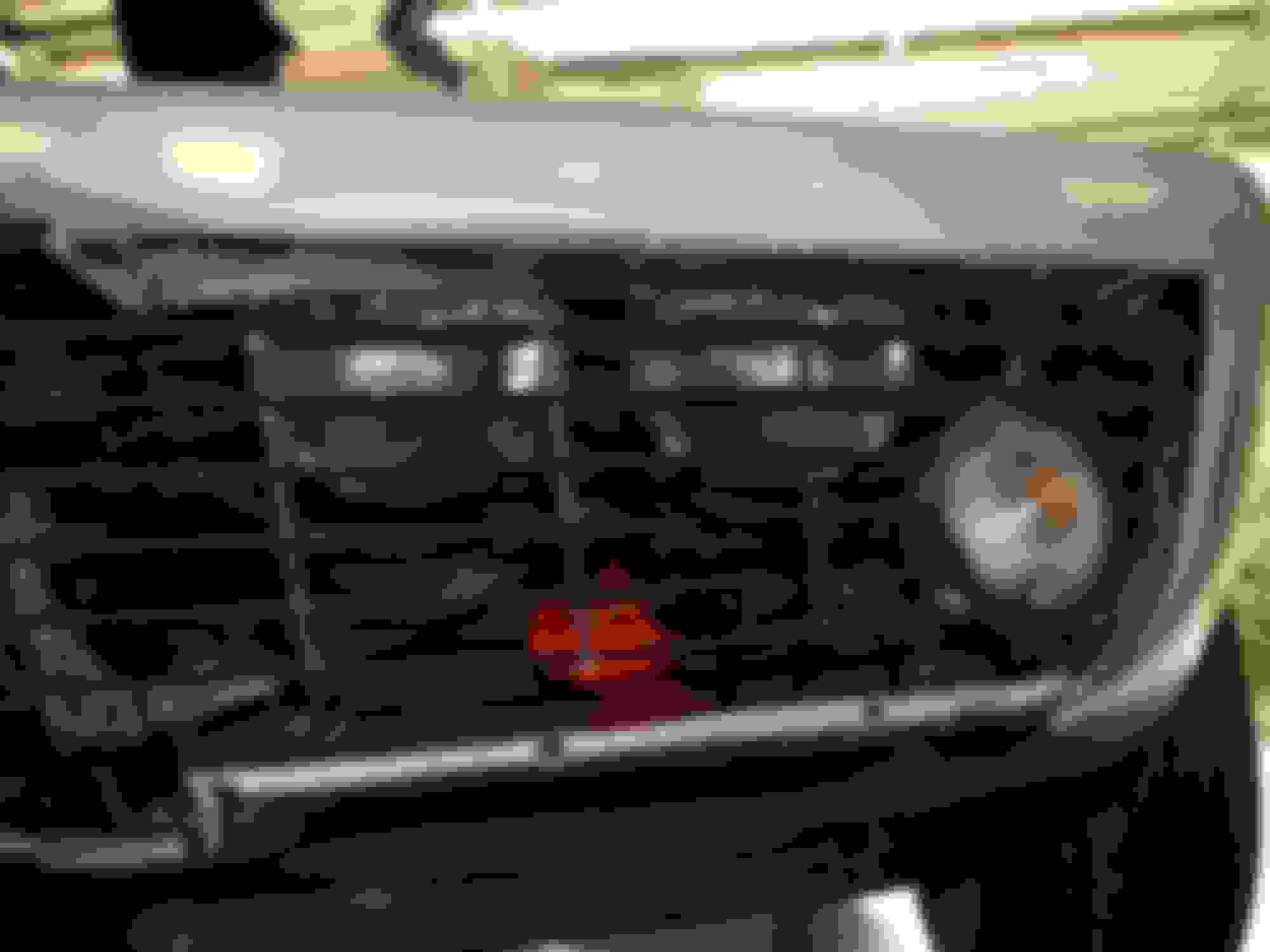
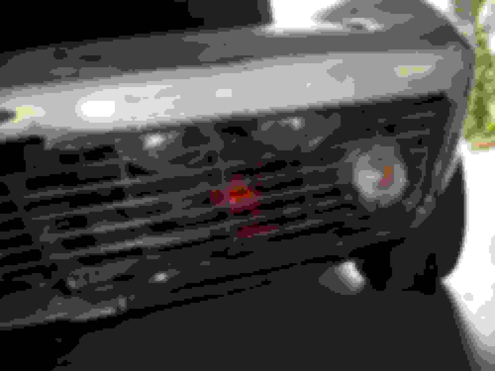
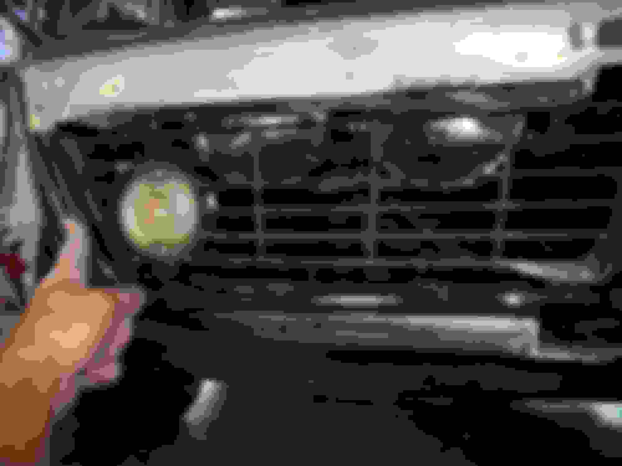
My '68 aftermarket grills are temporarily installed street-legal/turn signals by drilling small holes into the fiberglass lip and zip-tying the grills in place/this way I can test-drive the car and de-bug the drive-train while making the modification at the same time.........
(Sample reference pics are included)
Now for some cutting/zip-tying/ black marker outlining................
Following Members good advice (after trying my method ) I assembled the 3 piece grill..........................
I tried to fit it in place..........but it wasn't going to happen because the assembly was too wide for the '76 opening.........
So I removed the brackets and temporarily zip-tied the three pieces together.....then I zip-tied them to the outside of the opening to see exactly what was interfering with the assembly........
Ahaaaa....the openings need to be widened 5/8" on each end and slightly re-shaped to allow the assembly room to fit in............
Sample pics provided by JC68.................................... .....
Now to find a marking pen and outline the outer edges of the grill assembly/then put a fresh blade in the jig saw.
The two lower grill trim pieces should arrive this afternoon which will be a big help in the fitting process.
The opening is marked on each end for the cut.........passenger side shown.............................
The rough cut is made/fiberglassing comes later...................
The driver-side cut is made......................
The corner pieces are saved for future re-fitting/fiberglassing...........
Zip-ties hold it in place for a test fit..............................
The outboard grill pieces will be bolted to the brackets and then mounted in the opening..........then the center grill can be set deeper into the opening/attached to the inboard brackets/then the lower valence can be cut/notched so that the two chrome bumper guards can be bolted in the location where the two previous "rubber" bumper guards existed.
The pic exaggerates the way the grills fit................
Back to the garage!
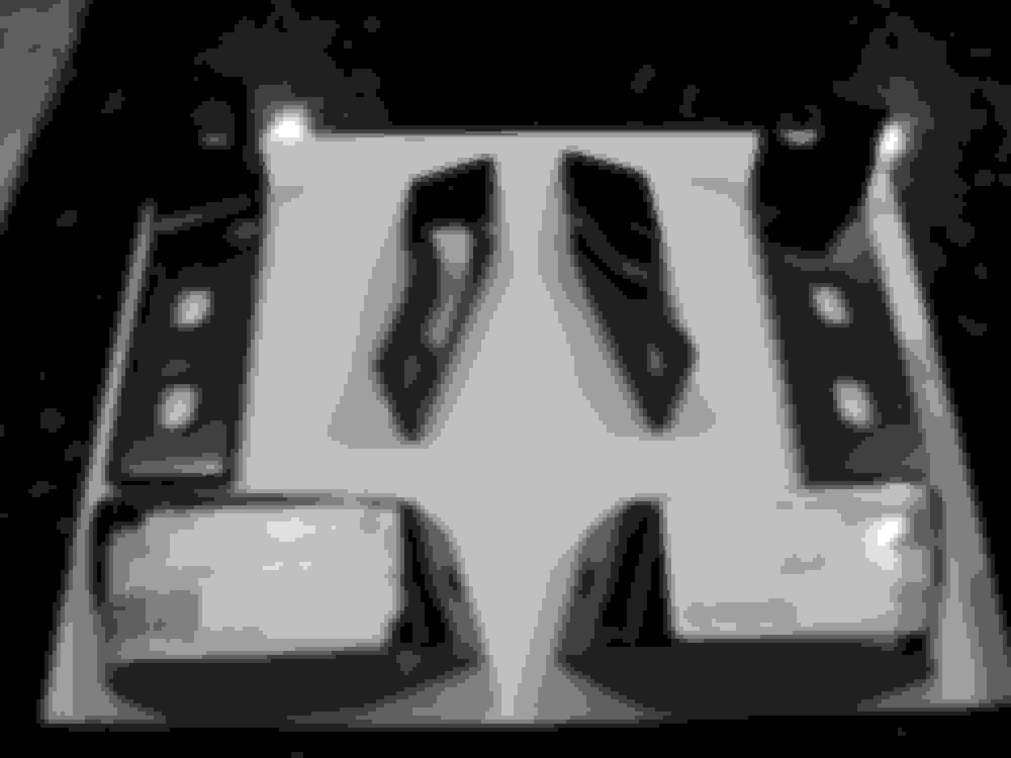
The four grill brackets are laid out for installation..........
Another half- hour's work has the driver side brackets installed on the grill.....I had to "adjust" the angled mounts on the bottom of both several times to fit the inside of the '76 clip/nose.............
The assembly is rough-fit flush with the opening for now until I can look at the sample pics closer to get an idea of how much inset is needed......................
More grill work today............................
The center grill will not go into place even though I have widened the opening the correct amount/plus 1/4"...........
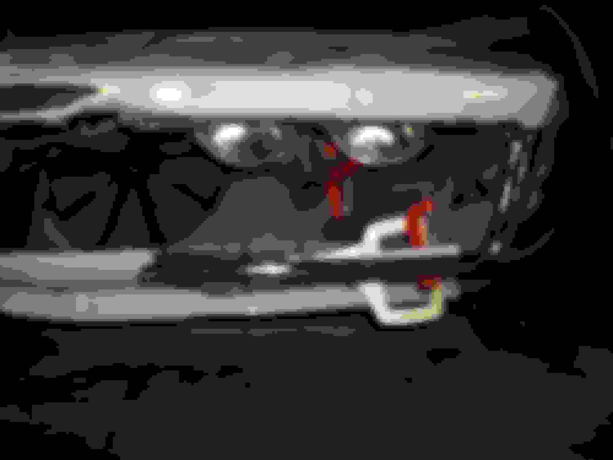
The main bend/angle of the brackets is facing the wrong way (weird!) causing the bad fit.........the two pics below show wrong angles on two brackets.........
The inner and outer ends of the grills fit decently after I straightened the 4 brackets using a plastic-tipped hammer and the vice to hold the brackets steady.........................
The assembly fits well on the ends/the center grill brackets need to be positioned---holes drilled in the lower valence to mount the brackets so the center grill will be "square" with the radiator.
The center of the valence needs to be notched after the center grill is squared up/then the entire opening needs to be re-fiberglassed in order to have the correct clearance.
NOTE: The width from the CENTER of the Center Grill to the outside edge of the widened opening is 24"......Total width is 48"......This may be different on another car/depending on the Year/Model of the front clip........
MORE MEASUREMENTS WITH '68 AND '76 COMPARISON PICS...............................
'76
YES.....IT'S TRUE........THE '68 NOSE/BUMPER AREA IS WIDER THAN THE '76 AREA!
It's time to move the trim pieces to the garage....................
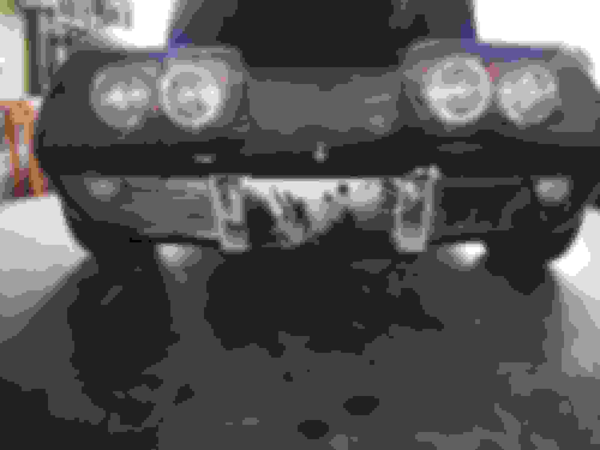
Ignore the red airhorns and loose wiring/vacuum hoses/LOL/that will be re-done before the final grill mounting takes place.
While I'm waiting on the lower valence to arrive this afternoon (which I need in order to locate the chrome trim and chrome bumper guards).....I may as well practice drilling some mounting holes in the '76 valence.........After I drilled the holes measuring downward from the top of the opening I saw that the '76 valence had been installed 3/4" too low........which left very little fiberglass support for the mounting holes (NO problem....I will make sure to install the new valence with the correct gap from top to bottom of the opening...........
I had to widen the edge gap another 1/4" between the fender and the edge of the grill so the chrome trim would have room to pop into place.
The chrome trim is actually parallel with the top of the opening/I will have to "adjust" the metal grill brackets later so that the grill will be parallel with the chrome trim..........
Back to the garage to mock up the passenger-side chrome trim.
More work.....this time on the passenger-side grill opening.....I measured from the top opening and sketched a line with my marking pen along the lower lip of the opening/then sawed the excess off/I also had to widen the outer edge 1/4" for the chrome trim to fit between the fender and the grill edge/I then held the chrome trim in place and parallel to the upper opening and traced under the trim piece where extra fiberglass was in the way.........
I smoothed the jagged edges a little/held the trim in place again and marked the stud holes for drilling/I then drilled the holes--same problem as the other side--no big deal---this valence is the "Practice Valence"...................
The trim piece is fitted/a little trimming here and there/then the trim is popped into place/this side took less than an hour to fit........
It is easy to see the sag in the valence at the inboard end of the chrome trim.
The '68 valence waiting it's turn.....................
I held the '68 valence under the '76 valence and scribed an outline into the paint.....then I made a cut leaving 2" all the way around the Inside of the scribe line so I would have a temporary area to clamp the new valence to.................
Next I clamped the new '68 valence in place to see if I was going in the right direction..............
May as well zip-tie some chrome to it........................
Some trimming needs to be done before I add a couple layers of fiberglass to the inside of the new valence.
Remember.......my goal is to make this as painless as possible while making the '76 clip look similar to a '68 clip/if I can get very close using your ideas I won't bother looking for a '68 clip later on......
BUT.......
I'm also going slowly to see how your molds turn out so I might be able to incorporate your ideas while using my $160 new valence in the process......I guess I COULD return the new valence if need be (I'll check Eckler's return policy on "sale items"/I could certainly use a REAL RADIATOR SUPPORT!).....
(Also.......there is some "Heavy Duty Creative Brace and Bracket Work" in the nose of the car which I would rather not cut aloose........"What happens in Las Nose stays in Las Nose!)
CHANGE OF PLANS......I WILL REMOVE PART OF THE NOSE SO THE CHROME BUMPER WILL FIT. (IF I DO NOT REMOVE PART OF THE NOSE..........MY ONLY CHOICE IS TO CUT 2 & 1/2" FROM THE MIDDLE OF THE CHROME BUMPER---THEN REWELD THE BUMPER HALVES TOGETHER/HAVE THE REWELDED AREA OF THE BUMPER GROUND SMOOTH AND RECHROMED SO THAT THE WELD WILL NOT BE EVIDENT---WHICH WOULD BE THE EASY WAY TO FINISH THE CONVERSION AND WOULD COST THE SAME AS MODIFYING THE '76 FIBERGLASS TO LOOK LIKE A 1968-69 NOSE FROM THE FACTORY)
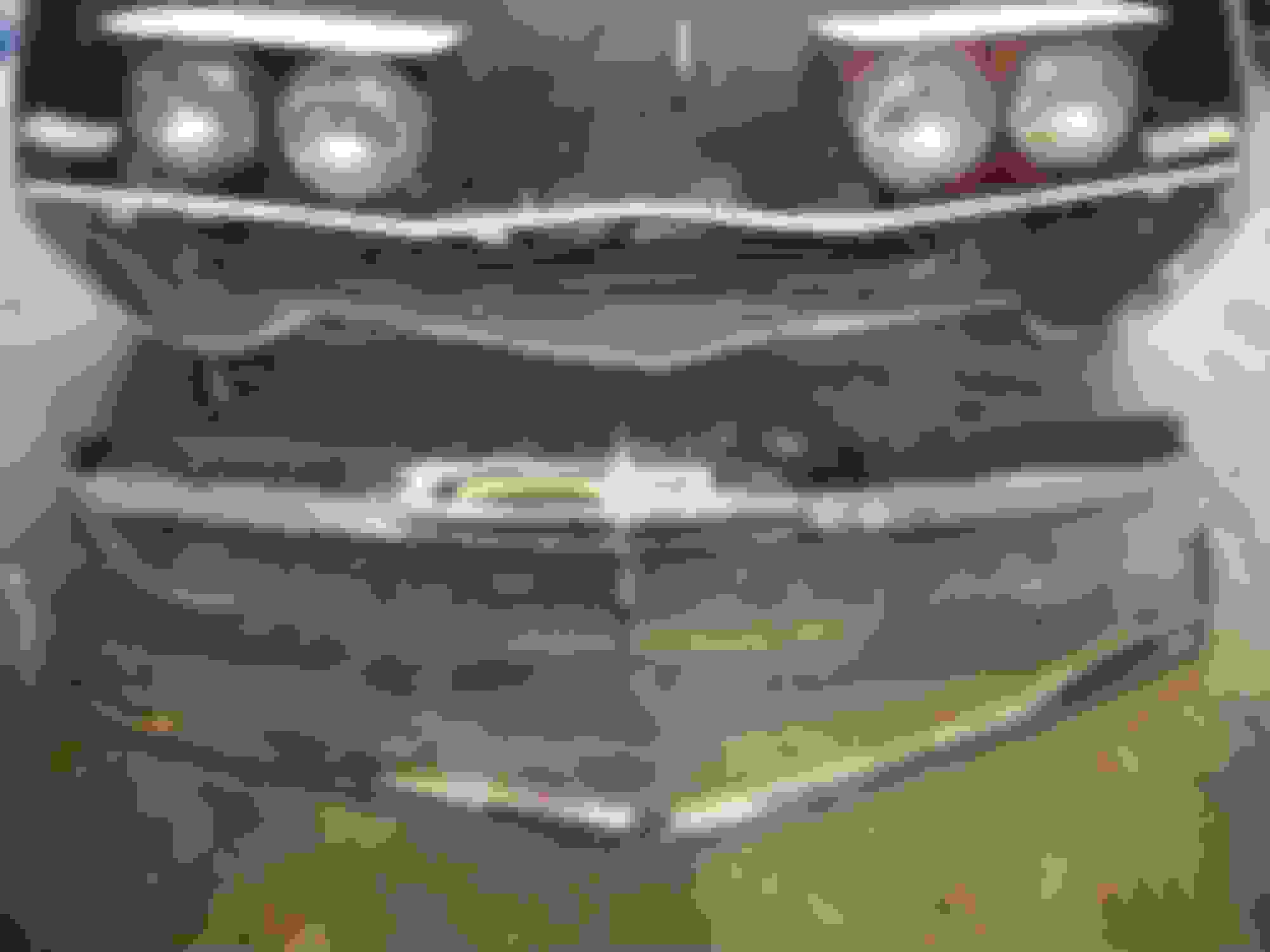
The first two pics show the problem with the chrome bumper/fiberglass gap that must be corrected..........All measurements are rough/approximate
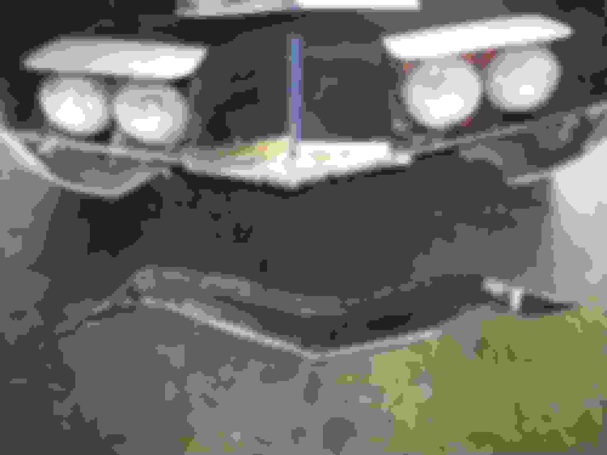
This shows the extra length of the '76 nose.....................
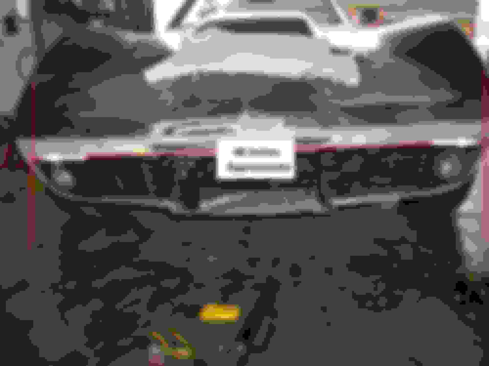
This shows the chrome bumper mocked-up acros the nose of the '76 clip..............
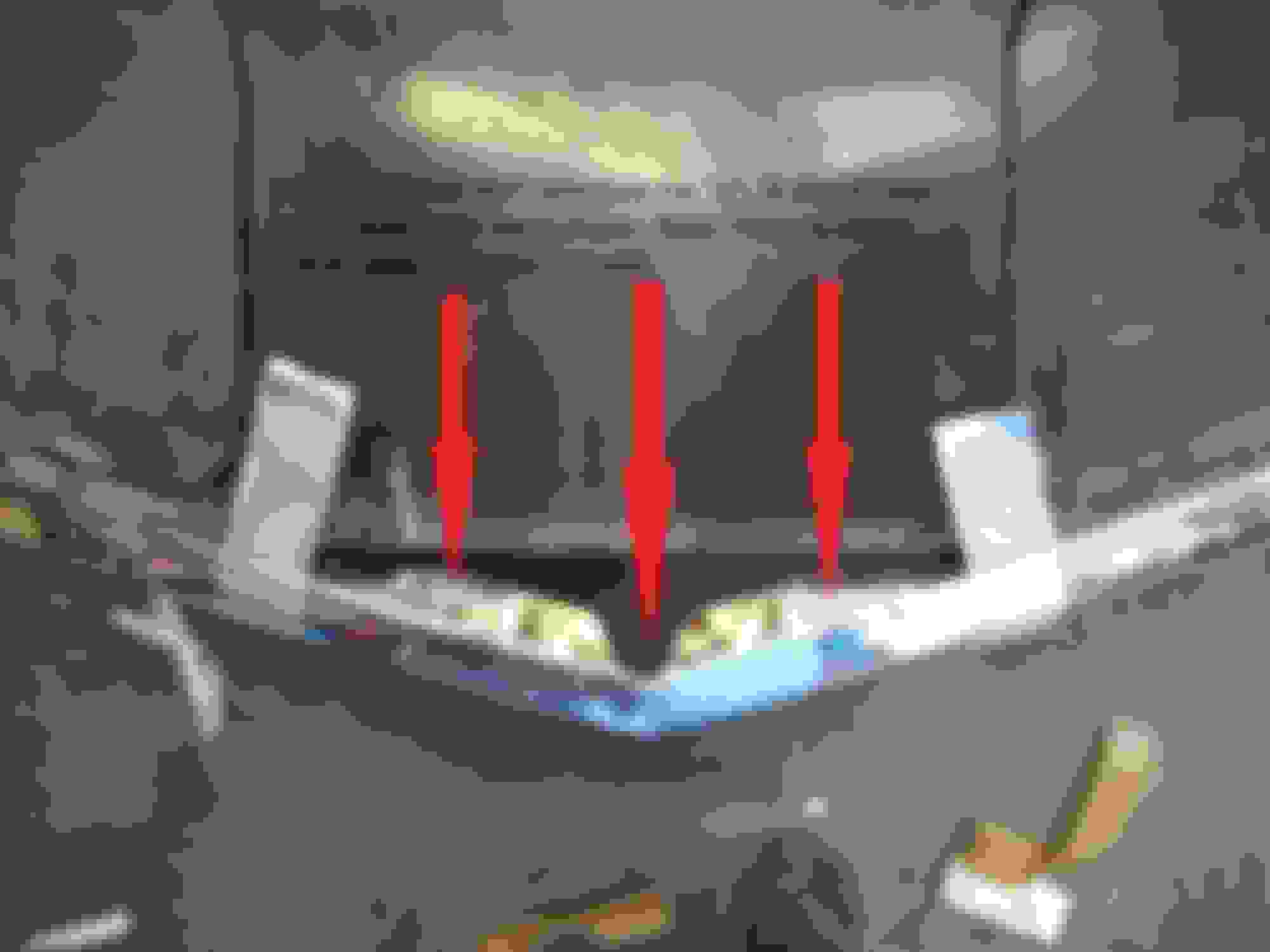
This shows the TOP TRAILING EDGE of the bumper about 5/8" from the headlight opening............
Doing the math/(.625"/area between headlight opening and bumper trailing edge + .625"/fiberglass "lip" that chrome bumper covers-fits over) - 3.750"/total flat area = 2.500" of extra flat area that must be remove so the leading edge of the fiberglass can be "moved rearward" the correct amount for the chrome bumper to be the correct distance from the headlight opening........
This shows the leading edge of the nose in front of the chrome bumper that needs to be re-attached to the clip after the extra flat area is removed............
First....I used 1/2" wide tape to layout the 1/2" flat area between the headlight openings and the "bumper notch" in the fiberglass.............................. ......
Then I made notes on the tape to keep everything in order.........
Then I laid the chrome bumper along the tape.............................
Since I only have pics to work from I laid the chrome bumper across the nose and taped it onto the car approximately where it should fit once the cutting is done (the camera angle distorts the distance from the chrome bumper to the leading edge of the nose)............
The center section of the white tape is run straight across between the headlights/rather than then V-shape I started with.........
NOTE: I SHOULD HAVE CUT ALONG THE ANGLED "V" (you can see the thin scribed "V" mark) RATHER THAN CUTTING STRAIGHT ACROSS BETWEEN THE HEADLIGHTS/THIS WOULD HAVE SAVED HAVING TO MAKE A PATCH-PIECE LATER ON!
I used an air grinder with a 1/8" thick cut-off wheel at 100 p.s.i. .......
I held the nose in place with aluminum duct tape (strong stuff) to keep it from binding on the cutting wheel.........
It took me 30 minutes of nervous cutting to keep the cut-off wheel under control.....once the nose was loose I propped it up in front of the car with a tool.....then laid the chrome bumper in front to get a pic of everything..........
More fiberglass cutting and fitting/getting closer to a final fit before filling in with fiberglass....................
I taped the bumper to the shortened cap as close as it would allow......
The gaps have been reduced from 1 & 1/4" down to 1/2" on each bumper corner..............
Areas are marked for more trimming along the top and side of each fenders.......the half-round white marks are to allow clearance for the bumper corner-mounting brackets/they will be filled in so the bracket will sit flush/then bolt holes will be drilled........
The cuts are made on both fenders................................. .
This is all I can remove without ruining the factory-designed 1/2" wide flat area between the headlight openings and the chrome bumper.........
The gaps between the bumper corners and the fenders is reduced down to 1/4"....................... ......................
WHEW! Time for a lunch break and let the nervousness settle down some before I make another trip to the garage.
I did a little more fitting this afternoon.......I took the fiberglass nose-piece that I cut off the car.............................
and cut a patch-panel out of the center............................
It's about 16 & 1/2" across and 3" deep by 1 & 1/2" high when on a workbench......I'll make a drawing of it once it's trimmed to size..........
It ALMOST fits/a little more trimming should let it pop into place....................
These are some measurements and angles I didn't realize that I needed......thanks to everyone who provided pics and info........the modification is getting closer to completion..........
More fiberglass cutting and fitting using newly acquired dimensions.....
Taping pics with dimensions in an easy-to-read location.........
Covering the car to keep fiberglass dust out of interior and masking off first cut on lower front of driver's fender.............
Un-needed fiberglass is removed........................
Checking angle of cut................................
Repeating process on the passenger side fender.......................
Removing remnant of '76 lower valence............................
Mocking up new lower valence and checking dimensions...........
SPECIAL NOTE: THIS IS THE POINT AT WHICH I COULD HAVE FIBERGLASSED A FLAT VERTICAL PIECE ACROSS THE LEADING EDGE OF THE NOSE FOR THE BUMPER TO "SIT" AGAINST.....THIS WOULD HAVE MADE THE CONVERSION MUCH EASIER AND LESS COSTLY. HOWEVER......DEREKDEREK MADE A SPECIAL "NOSE INSERT" FOR ME TO TRY ON MY CAR....THE INSERT WOULD GIVE THE NOSE A FACTORY LOOK....SO I GRATEFULLY ACCEPTED HIS OFFER.
Derek put all the dimensions/pics together and fabricated an experimental "nose/bumper section" for me to try on my project...He left enough extra material so that I can trim the pieces to fit...(I will not need the two small triangular fill-in pieces for the nose because derek incorporated enough extra fiberglass onto the insert to fill in the gap.....see pics below)
He even made the corners for the grill openings...............
derekderek will get a kick out of the experimental "nose insert" that he made/I will notch the '76 front end to fit the insert........you can see how much the fiberglass "straightened out" during shipment..................
I used painter's tape to gradually pull the piece against the back of the bumper.....................
The rear view of the insert...................
The fiberglass insert needed heating with the gun in several places/then C-clamping to hold the insert in place while it cooled off....
A little more progress on the front bumper conversion..........
NOTE: THIS IS THE POINT AT WHICH I CAUSED MYSELF 3 TIMES THE WORK NECESSARY TO COMPLETE THE FRONT BUMPER MODIFICATION.
IF I WOULD NOT HAVE CUT NOTCHES TO GRAFT IN "ORIGINAL-LOOKING" FENDER-TO-BUMPER FIBERGLASS SUPPORTS THE PROJECT WOULD HAVE BEEN FINISHED 70% SOONER!
The passenger side fender is scribed and notched for the fiberglass insert......
The insert wrap-around is test fitted to the fender............
The insert piece is taped inside the chrome bumper and also test fitted to the fender..............
The long section of the insert is rough-trimmed and test fitted........
***********THIS IS AS FAR AS I HAVE GOTTEN......I WILL ADD MORE PICS AS THE MODIFICATION CONTINUES**********
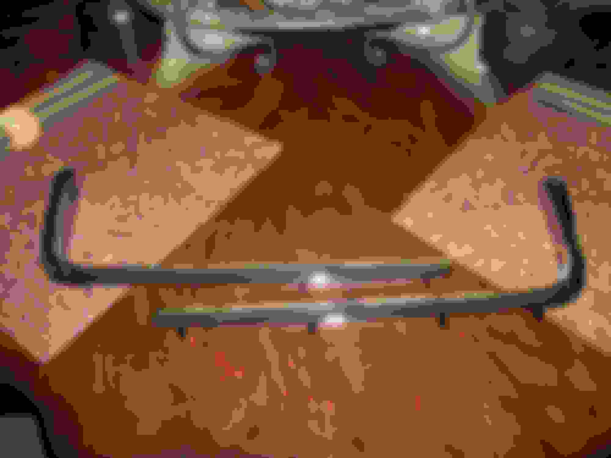
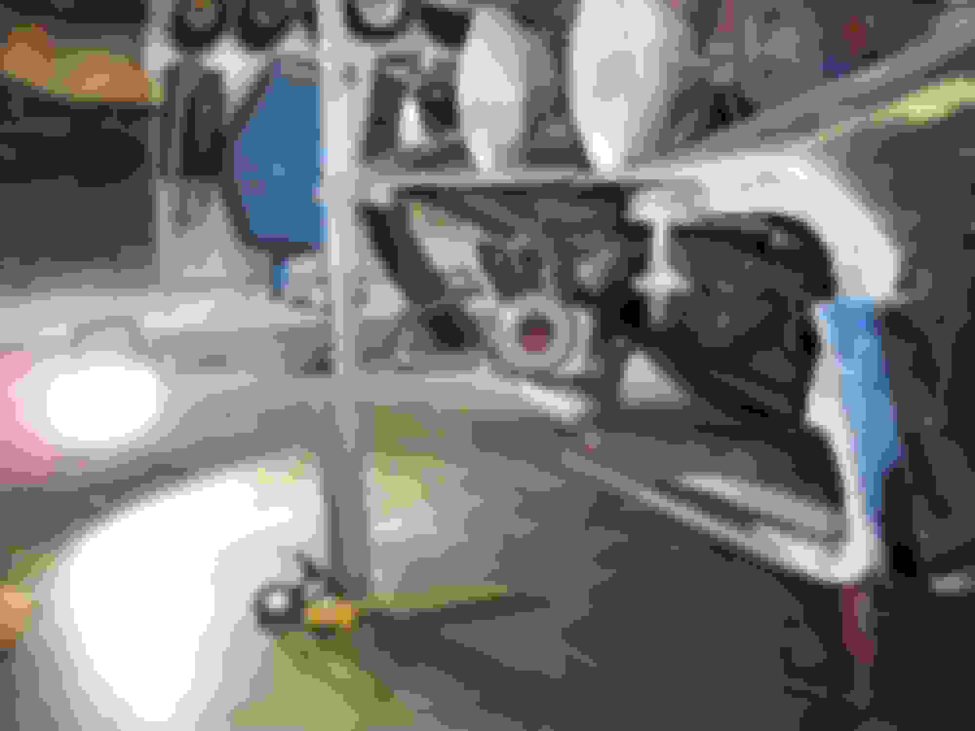
Time to remove the "custom" front lower crossmember..................
I THINK I'll go with the piece that is painted black...... ...........
Now back to the garage to remove the dents and clumps of weld on the underside of the frame.
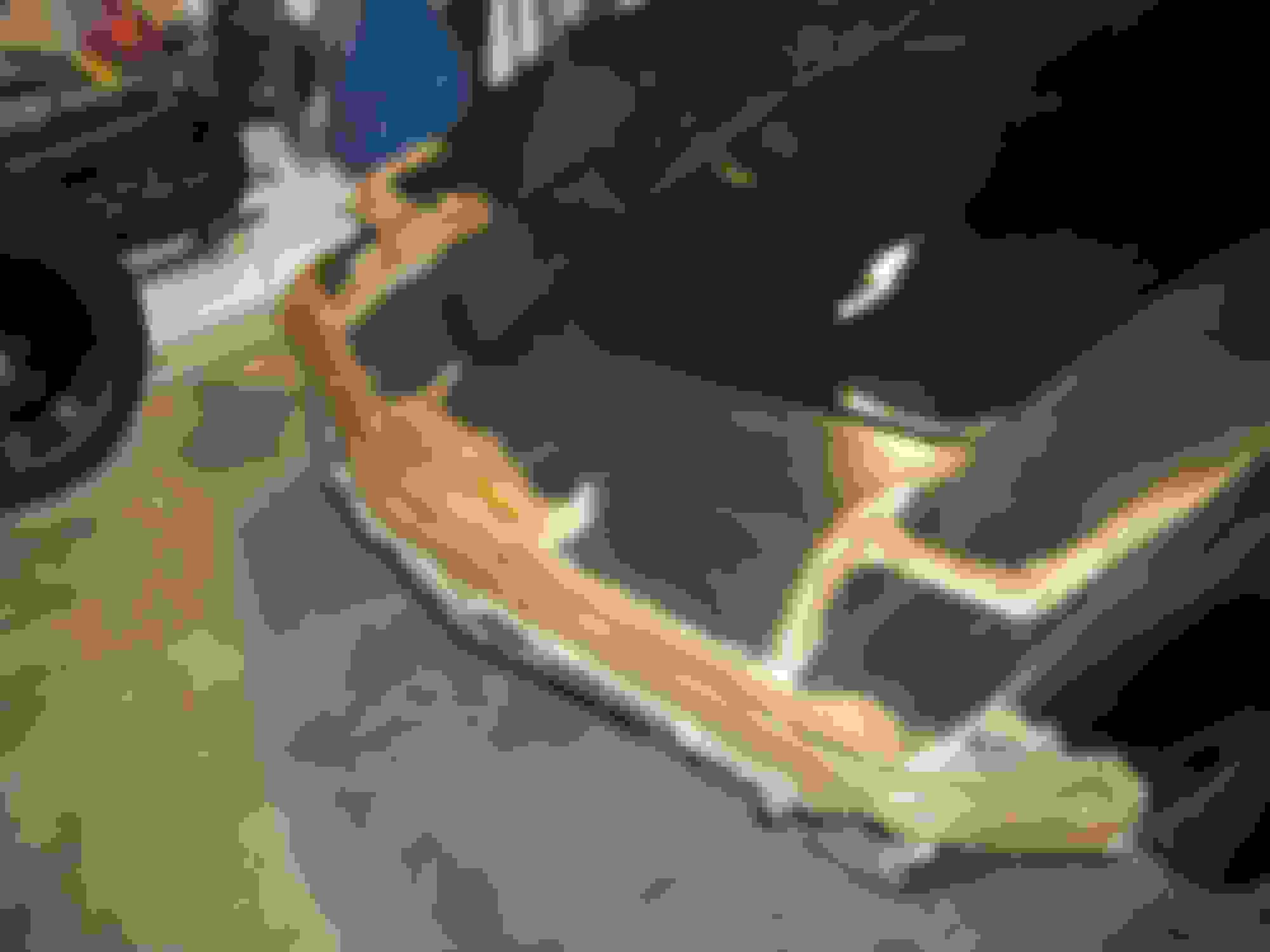
I had to remove the frame front extensions because the ends were bent and the front weld nuts were welded closed by Mr. Bubba.
The driver-side extension has a NICE bend on the front....................
45 minutes later it's ready to have 1 new nut welded onto the inside of the front end/the other nut is in good shape..............
Tomorrow I with take the bends out of the passenger-side extension and weld a new nut on the inside of the front end.
Here are some more "While I'm at it Pics". It's been 35 years since the car has seen these parts since Bubba didn't need them/he had a good supply of angle iron!!!
Here are the repair pics....not spiffy, but stout....spiffy will happen when I have the frame "Boiled" to remove the rust inside and out.....
"Corner" and weld nut completely missing?????.............
Area above repaired..............................
Angle Iron because............................????? ??.................
Member Mercury20 gave me a good deal on the crossmember $400 (just kidding)........I bolted the straightened extensions to it.......................
I ran out of bolts (had to cut the original bolts off)........so I butted the bumper extensions against the crossmember to get a complete pic of this morning's work......whew.....
I started installing the lower crossmember assembly.....it is slow going.
First I had to straighten the bumper brace...................
The bend on the left doesn't belong there..................
The driver-side frame extension and bumper support are installed/lots of grease on all bolt threads................................. ..
The passenger-side frame is de-rusted at the mating surface........................
The weld nuts are chased.................................. ....
The bolts are greased and the 2 pieces are bolted to the frame...........
Now back to the garage to bolt the lower crossemember to the frame extensions.
It's a good thing I took the advice on positioning the jackstands to prevent the frame from sagging!
I did manage to take some weight off the nose before I left this morning.........
I spent a couple hours repairing some cracked fiberglass next to the hood hinge/fender support and around the outer bumper brace.................
I will let it cure overnight before I put a couple layers of cloth on the back side of the inner fender panel.....then I will trim the edges and the opening around the bumper brace.
Thanks for the encouragement Men......I did some welding/repair/wir-brushing to the metal support that fits vertically inside the fender well and also fiberglased all the cracked areas.....I will grind away the excess fiverglass that overlaps dirty areas and smooth out/paint the finished fiberglass. Here are a few pics of some sloppy but stout work..........
For the good news.......I put the vertical fender/support (also holds radiator support in place) into place/cheated and used pop rivets to hold it in position.....then I pushed the 7/16" bolts into place......it's ugly but as usual I went for STOUT..........
I'll "beautify" the wheel wells this winter.
I haven't been able to work on the car lately, but I DID manage to open a little box of goodies.......now I have a good start on mocking up the front bumper so I can fit the fiberglass backing for the bumper.......
Braces and brackets................................ ..
Mocked-up fiberglass inserts that member DerekDerek fabricated for me............
Thanks everyone.....because the repair panels are different shapes I have to leave a couple "bad spots" and repair those pots before grafting the panels into place.
I will also leave an inch of excess fiberglass around the edges of all repair panels.....and at all areas of the clip that need to be cut out.
Derek made a good suggestion a couple weeks ago that I should leave the forward wheel well "splash panel" intact since it is bonded well to the clip, which means I will trim the repair panel for the driver's side more than I normally would have.
The splash panel for the passenger's side is completely un-bonded so I will have to "pull the fender inward" until it touches the splash panel bonding strip/then bond it to the original part of the fender to match the driver's side splash panel.
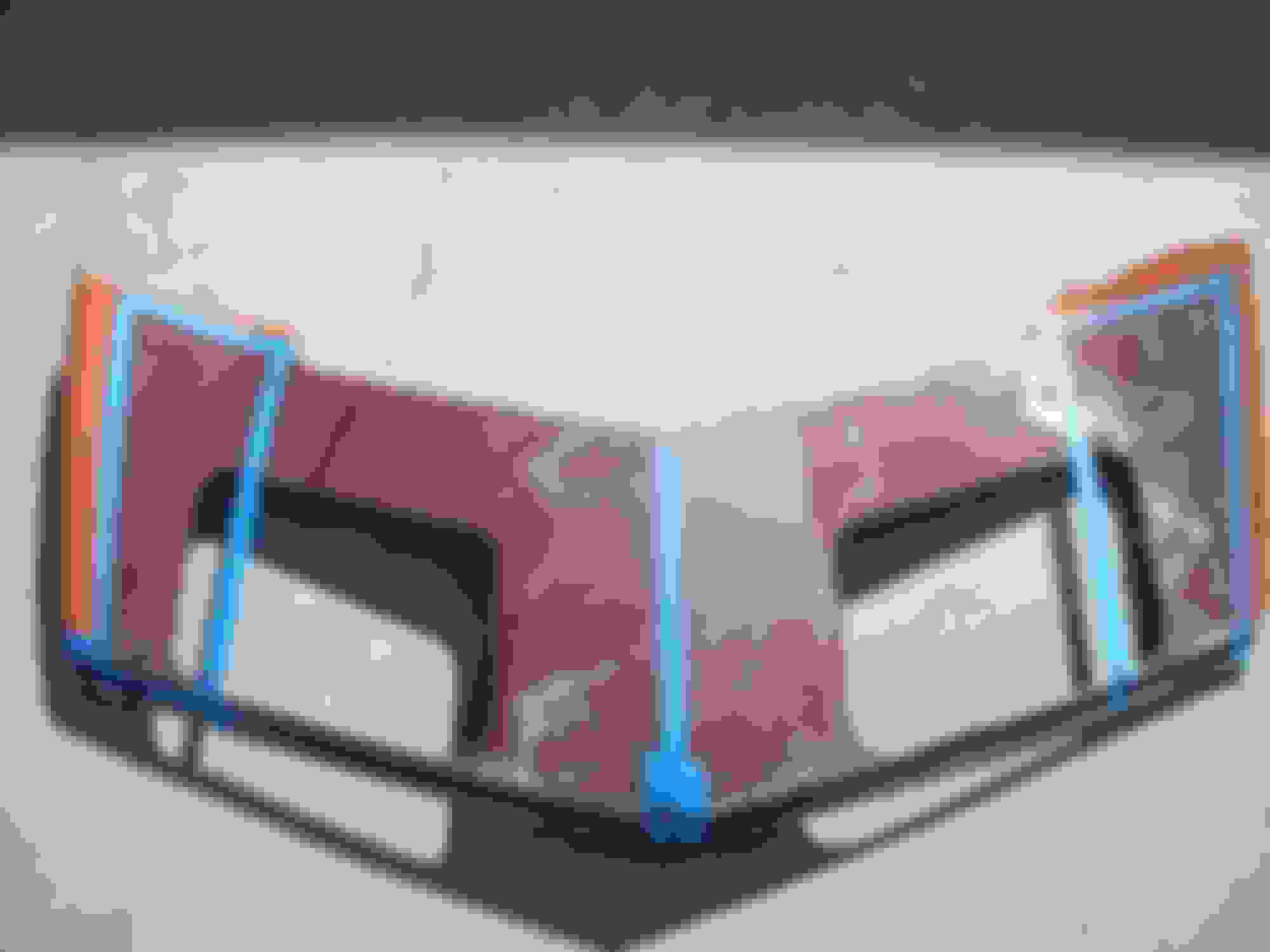
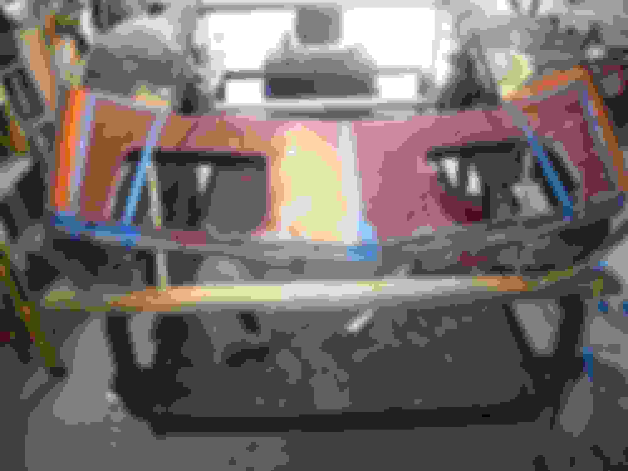
SO...….HERE GOES THE CUTS I WILL MAKE.....IF ANYONE SEES ANYTHING WEIRD PLEASE POST YOUR CONCERNSAND USE THE REFRENCE NUMBER ABOVE EACH PIC IN QUESTION...…...…...…...………...….......... .
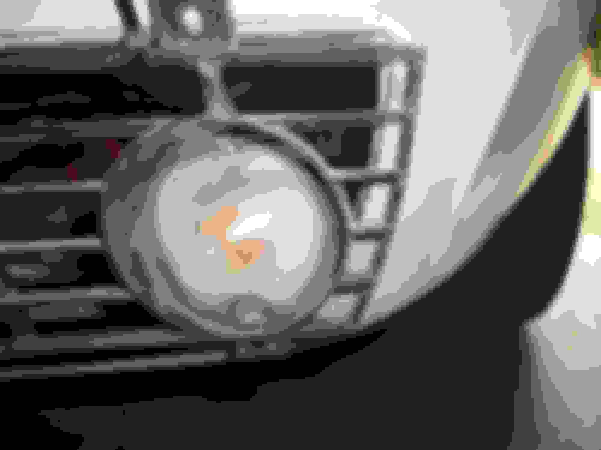
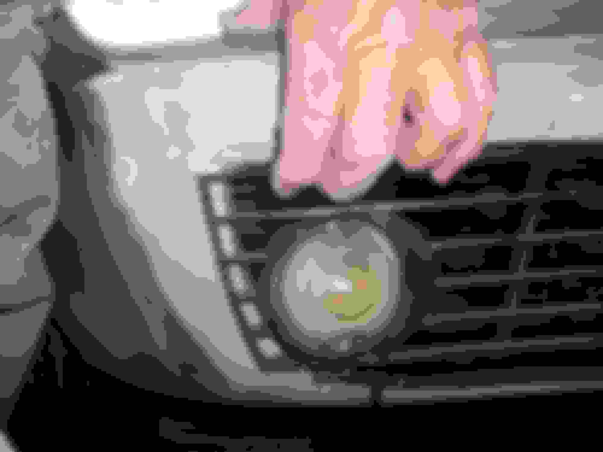
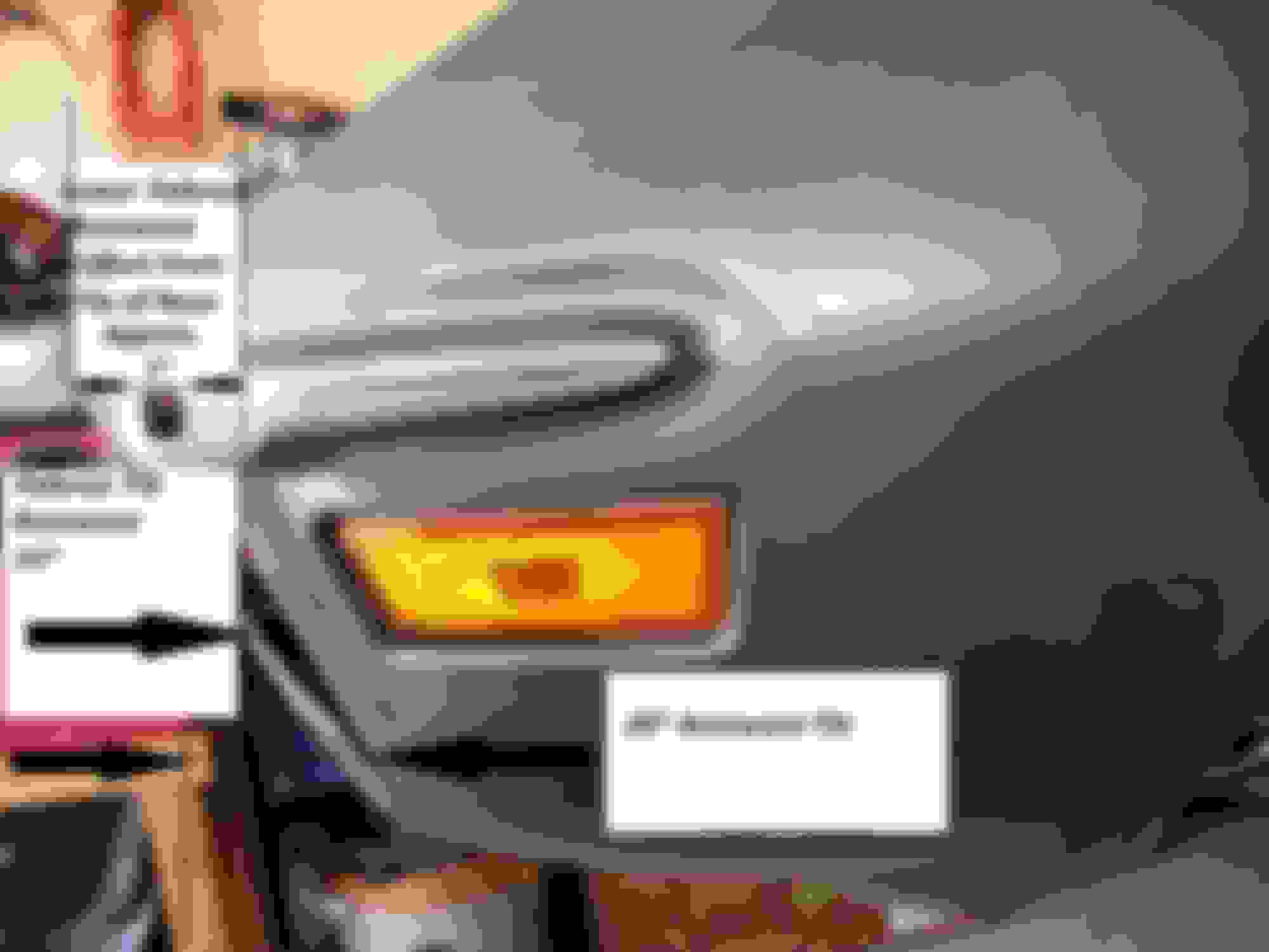
PIC #1 The areas with orange paint will be cut off...……...
PIC #2 1976 damaged nose "clip"...……..
PIC # 3 Headlight repair panel resting on clip......…...……….
PIC #4 Front view...………………………...
PIC # 5 Entire cut to be made for new fender repair panel which will bond to splash panel...……………….
PIC # 6 Repair panel with masking tape outlining cut to be made to overlap splash panel bonding strip...…………...
PIC #7 Driver's side cut to fit headlight repair panel...…...
PIC #8 Passenger's side cut to fit headlight repair panel...…………..
PIC #9 Passenger's side reapir panel being fitted...…………………..
Continued...................
Thanks everyone.....because the repair panels are different shapes I have to leave a couple "bad spots" and repair those pots before grafting the panels into place.
I will also leave an inch of excess fiberglass around the edges of all repair panels.....and at all areas of the clip that need to be cut out.
Derek made a good suggestion a couple weeks ago that I should leave the forward wheel well "splash panel" intact since it is bonded well to the clip, which means I will trim the repair panel for the driver's side more than I normally would have.
The splash panel for the passenger's side is completely un-bonded so I will have to "pull the fender inward" until it touches the splash panel bonding strip/then bond it to the original part of the fender to match the driver's side splash panel.
SO...….HERE GOES THE CUTS I WILL MAKE.....IF ANYONE SEES ANYTHING WEIRD PLEASE POST YOUR CONCERNSAND USE THE REFRENCE NUMBER ABOVE EACH PIC IN QUESTION...…...…...…...………...….......... .
PIC #1 The areas with orange paint will be cut off...……...
PIC #2 1976 damaged nose "clip"...……..
PIC # 3 Headlight repair panel resting on clip......…...……….
PIC #4 Front view...………………………...
PIC # 5 Entire cut to be made for new fender repair panel which will bond to splash panel...……………….
PIC # 6 Repair panel with masking tape outlining cut to be made to overlap splash panel bonding strip...…………...
PIC #7 Driver's side cut to fit headlight repair panel...…...
PIC #8 Passenger's side cut to fit headlight repair panel...…………..
PIC #9 Passenger's side reapir panel being fitted...………………….. Thanks everyone.....because the repair panels are different shapes I have to leave a couple "bad spots" and repair those pots before grafting the panels into place.
I will also leave an inch of excess fiberglass around the edges of all repair panels.....and at all areas of the clip that need to be cut out.
Derek made a good suggestion a couple weeks ago that I should leave the forward wheel well "splash panel" intact since it is bonded well to the clip, which means I will trim the repair panel for the driver's side more than I normally would have.
The splash panel for the passenger's side is completely un-bonded so I will have to "pull the fender inward" until it touches the splash panel bonding strip/then bond it to the original part of the fender to match the driver's side splash panel.
SO...….HERE GOES THE CUTS I WILL MAKE.....IF ANYONE SEES ANYTHING WEIRD PLEASE POST YOUR CONCERNSAND USE THE REFRENCE NUMBER ABOVE EACH PIC IN QUESTION...…...…...…...………...….......... .
PIC #1 The areas with orange paint will be cut off...……...
PIC #2 1976 damaged nose "clip"...……..
PIC # 3 Headlight repair panel resting on clip......…...……….
PIC #4 Front view...………………………...
PIC # 5 Entire cut to be made for new fender repair panel which will bond to splash panel...……………….
PIC # 6 Repair panel with masking tape outlining cut to be made to overlap splash panel bonding strip...…………...
PIC #7 Driver's side cut to fit headlight repair panel...…...
PIC #8 Passenger's side cut to fit headlight repair panel...…………..
PIC #9 Passenger's side reapir panel being fitted...…………………..
Thanks again R.R...…...I'm learning from the best....if I try to list names I know I will forget someone!
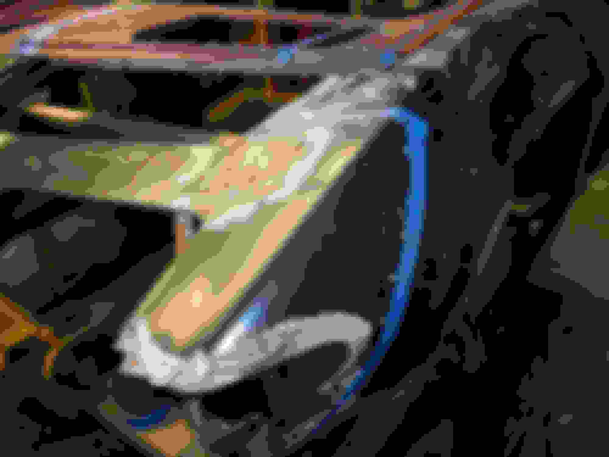
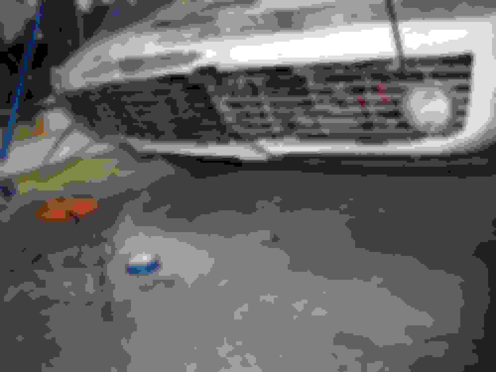
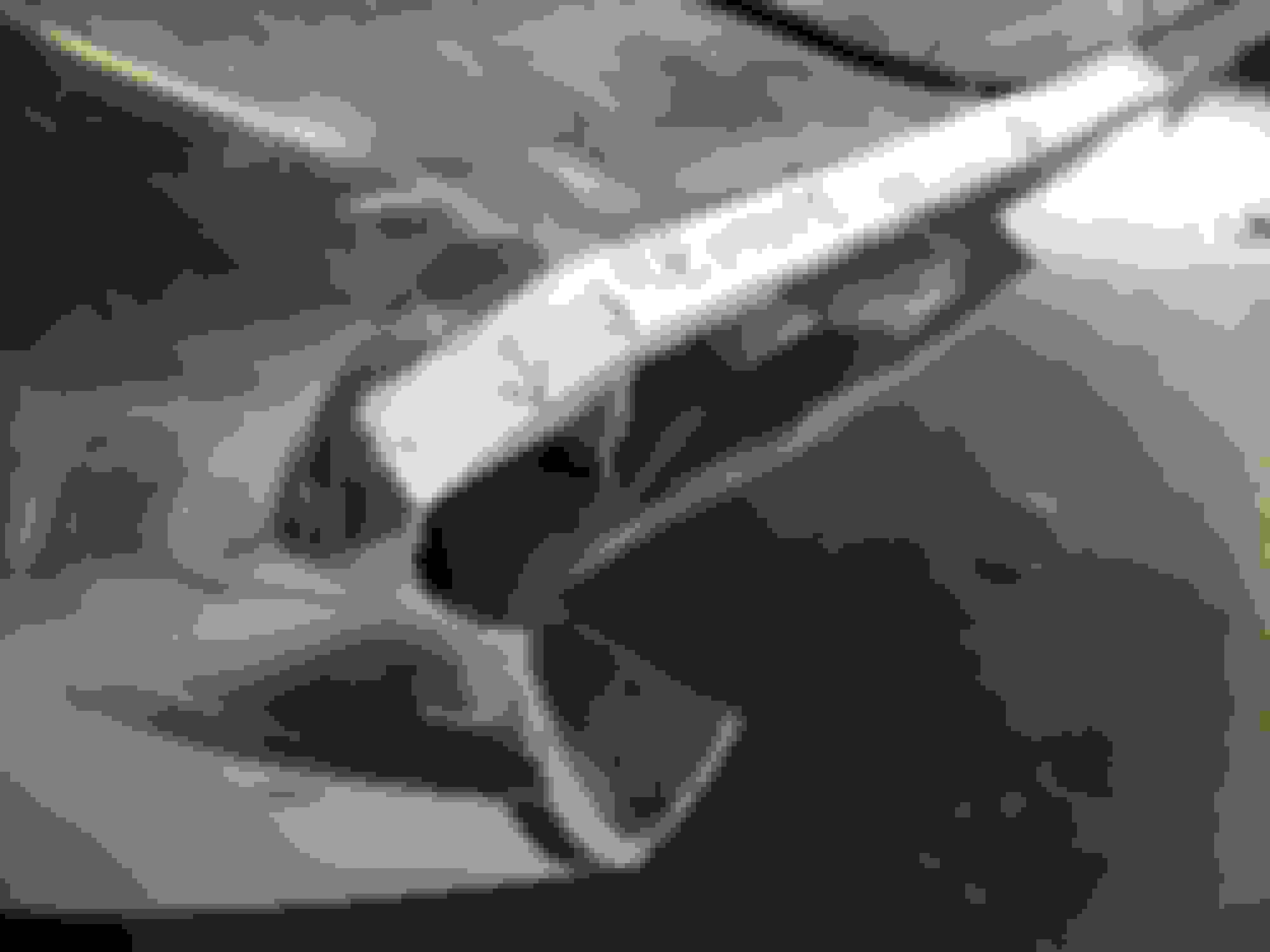
This afternoon I was working on the Harley and walked by the front clip a few times.....then I snapped and grabbed the side grinder that has the 1/16" wide cutoff wheel mounted on it. About five minutes and a cloud of dust later the passenger fender forward of the wheel well was chopped...…..(I will need to cut a repair piece to replace the damaged/peeling ridge...….you can see the splash panel dangling since it came completely loose from the inner side of the fender...………..
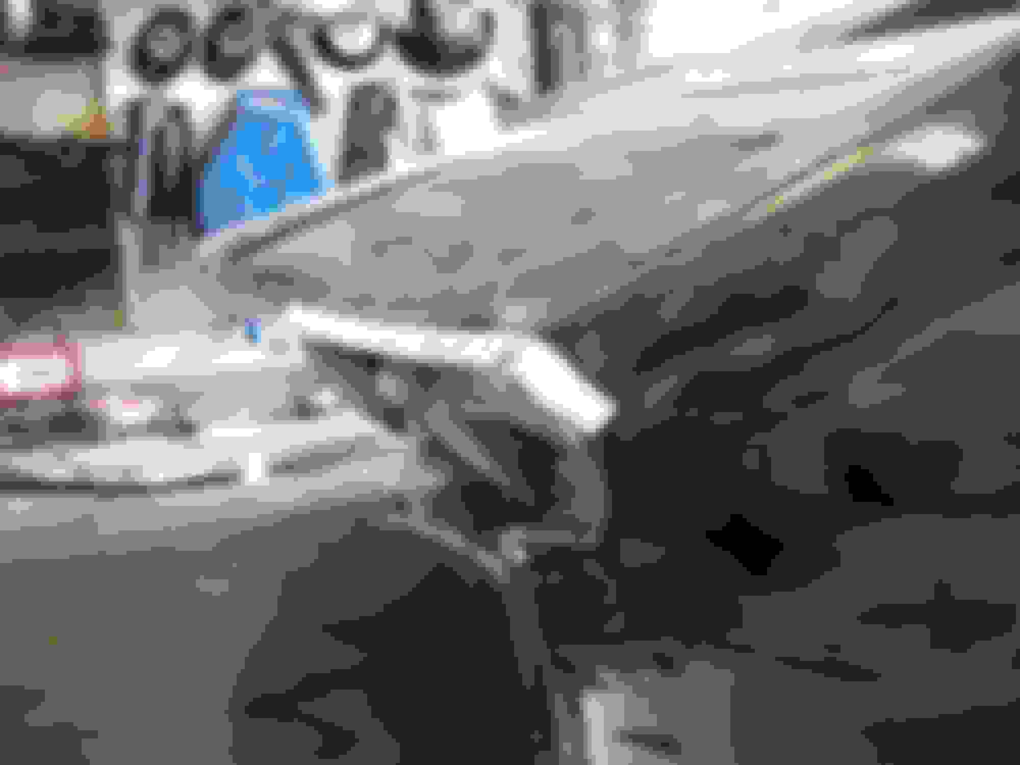
The repair panel taped in place...……...
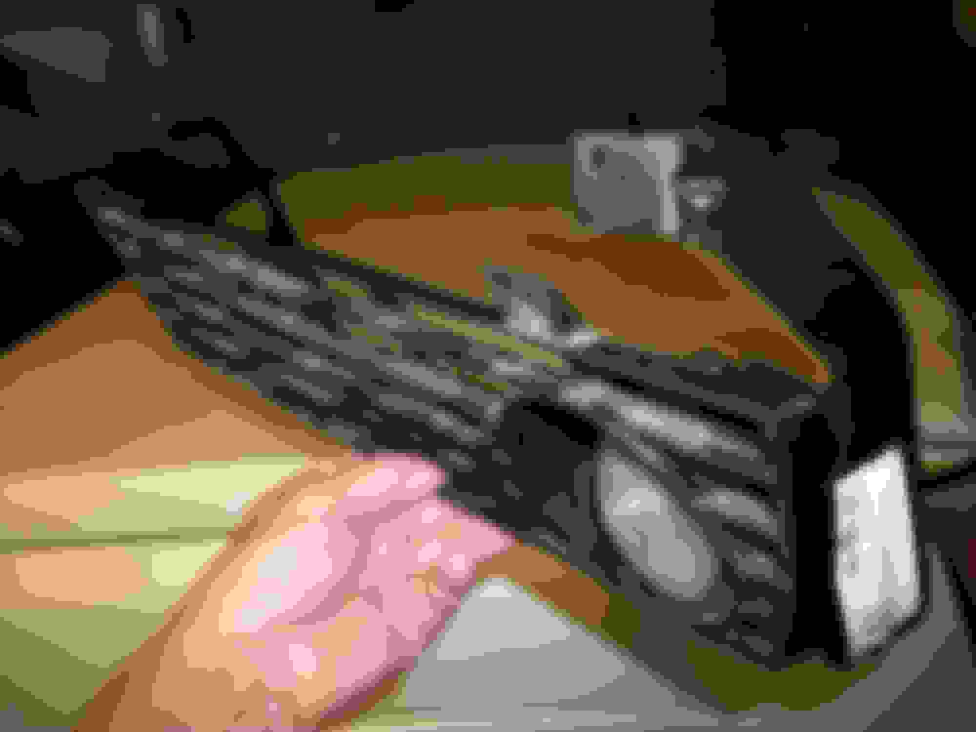
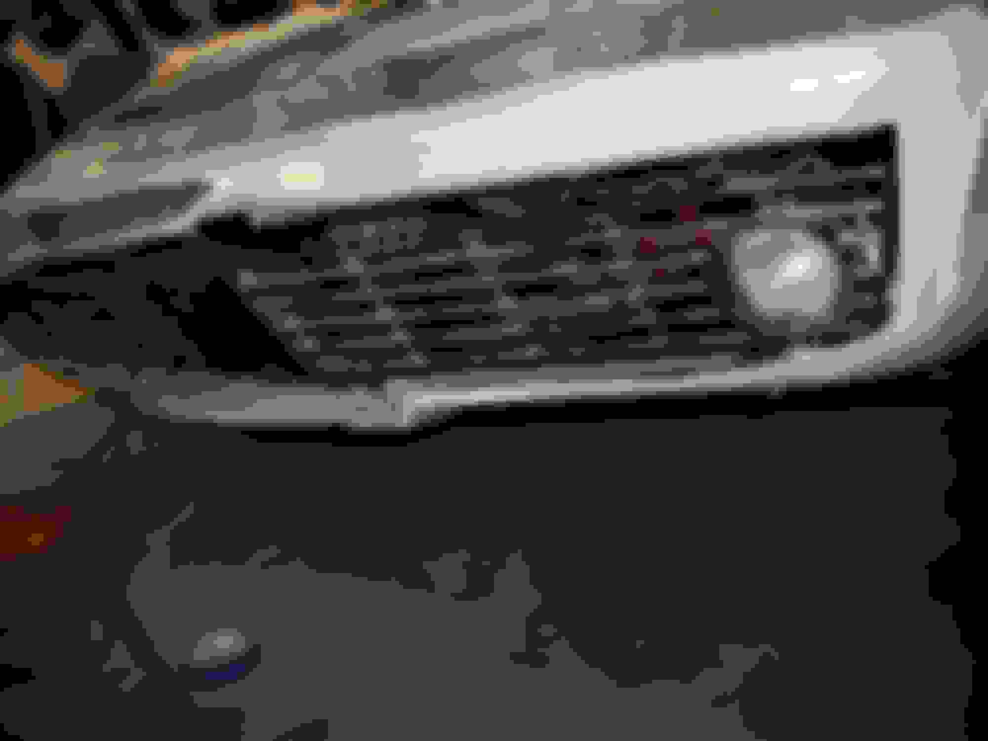
So.....then I cut the headlight panel loose from the passenger-side of the cap...……….
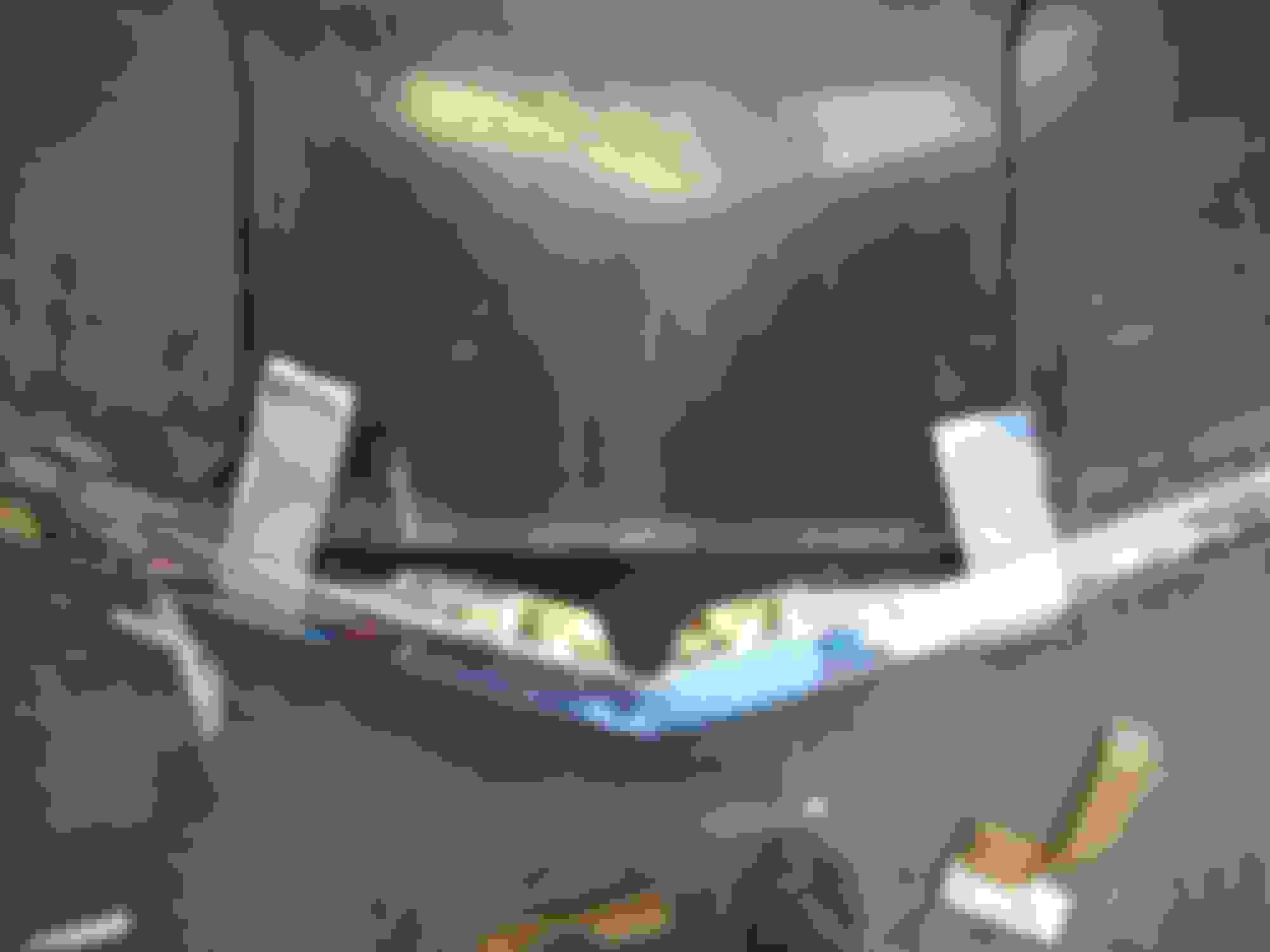
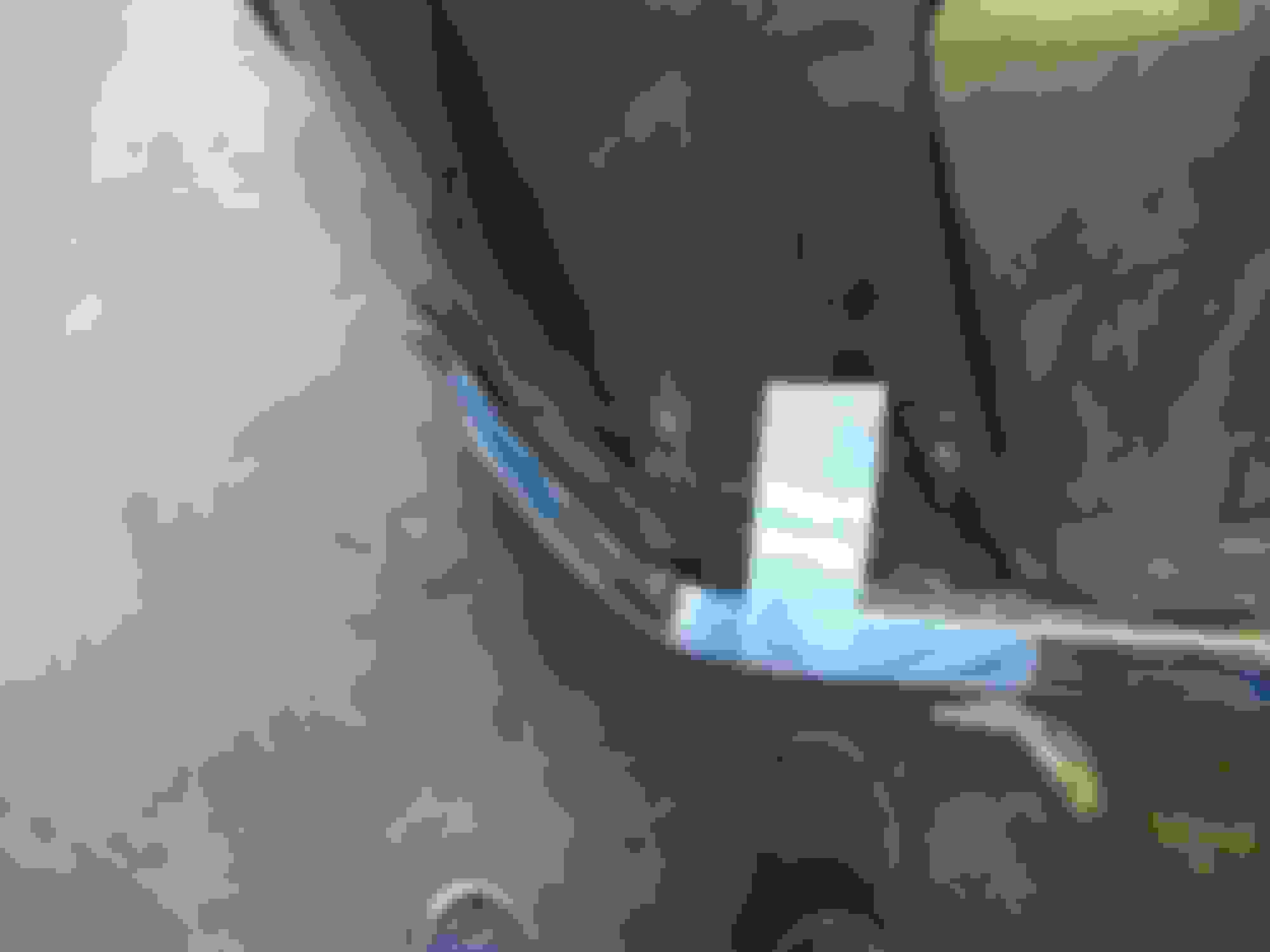
I placed the headlight repair panel roughly in place to have an idea of where the next cuts will be. I should be able to cut away the damaged/peeling piece shown in the picture once the headlight repair panel drops into position…….…...
Continued............
Thanks again R.R...…...I'm learning from the best....if I try to list names I know I will forget someone!
This afternoon I was working on the Harley and walked by the front clip a few times.....then I snapped and grabbed the side grinder that has the 1/16" wide cutoff wheel mounted on it. About five minutes and a cloud of dust later the passenger fender forward of the wheel well was chopped...…..(I will need to cut a repair piece to replace the damaged/peeling ridge...….you can see the splash panel dangling since it came completely loose from the inner side of the fender...………..
The repair panel taped in place...……...
So.....then I cut the headlight panel loose from the passenger-side of the cap...……….
I placed the headlight repair panel roughly in place to have an idea of where the next cuts will be. I should be able to cut away the damaged/peeling piece shown in the picture once the headlight repair panel drops into position…….…...
Last edited by doorgunner; 08-09-2021 at 10:17 PM.
I didn't get many pics of New Orleans......there was a b-a-a-a-d thunderstorm......no pics of the French Quarter, Jackson Square..........muggy day/foggy windshield/foggy pics......................... ...........................
Love it.
The spousal unit and I visit NOLA 3 or 4 times a year from Jackson, Mississippi. I'm looking forward to driving the '77 down there this fall.


 09-05-2015, 05:25 PM


 ) I assembled the 3 piece grill..........................
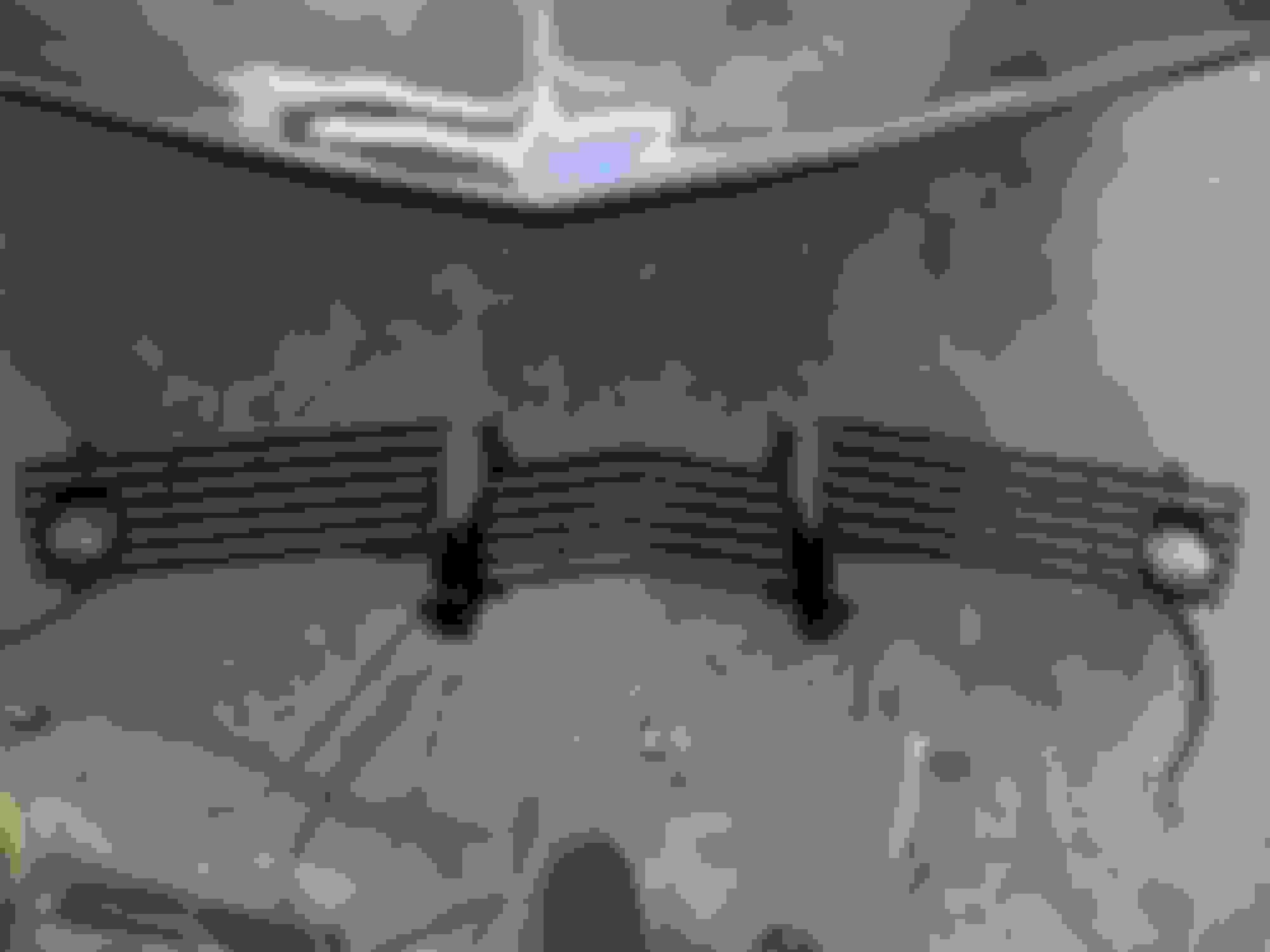


 ......................


 ...........