When you click on links to various merchants on this site and make a purchase, this can result in this site earning a commission. Affiliate programs and affiliations include, but are not limited to, the eBay Partner Network.
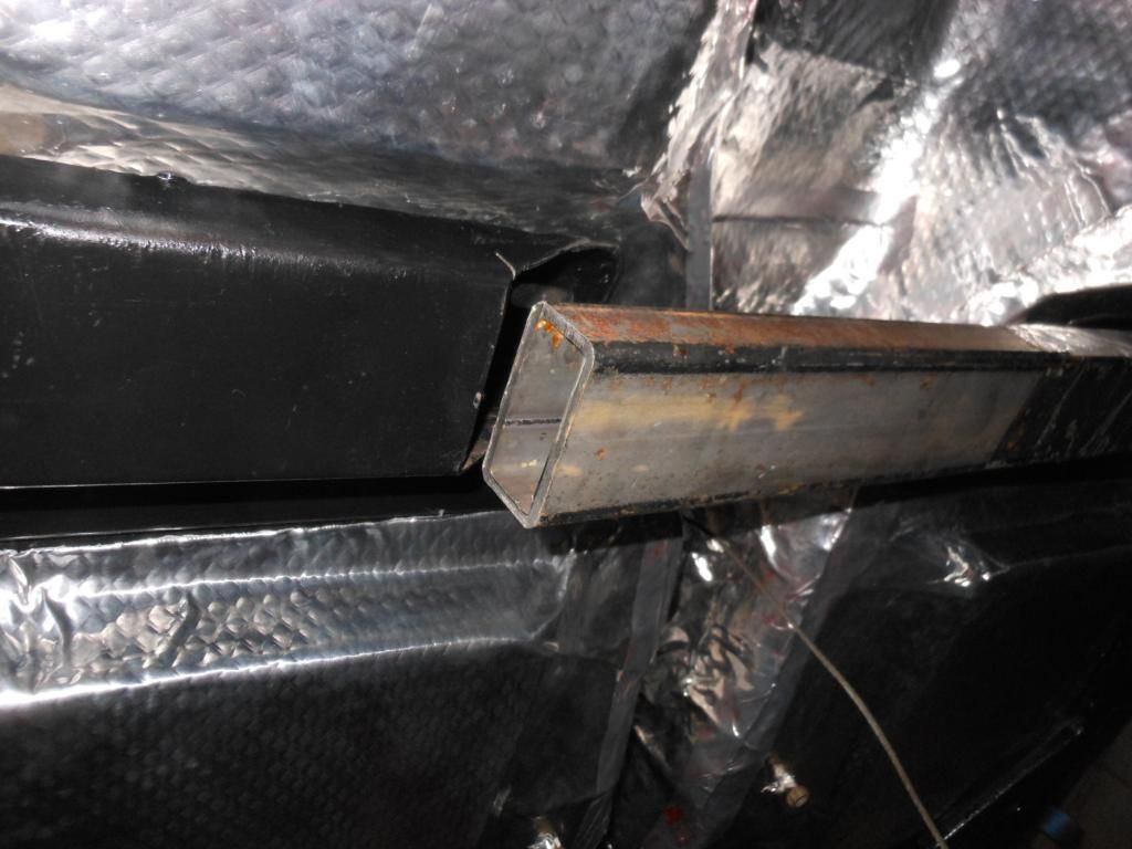
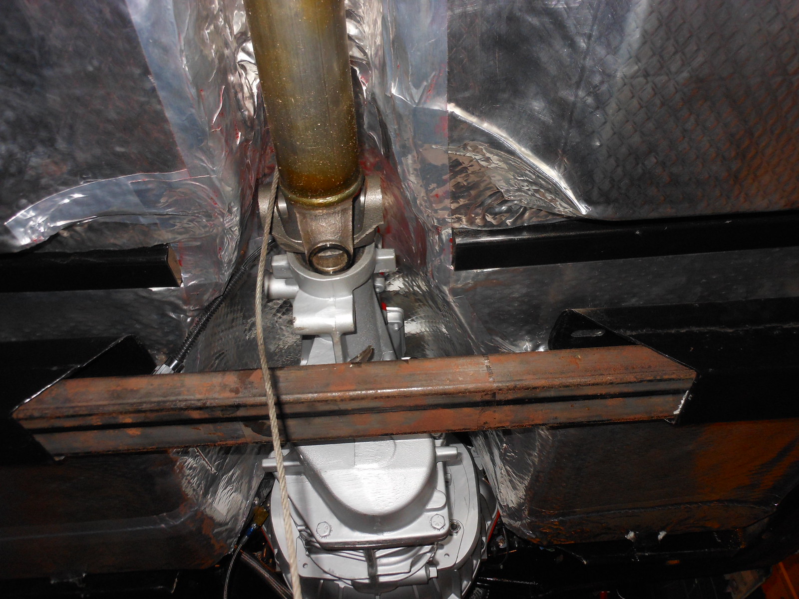
I am wondering if anyone has the crossmember cross section dimensions including the size of the radius. I have some 1/4" plate steel, and would like to make mine removable. I know they have plates precut for this, but $150 is kinda steep, even with the 'Corvette tax' .
Two suggestions of options:
(1) I have a set of the removeable crossmember plates. I can trace the outline of one on a piece of thick white paper and air mail it to you. The opening for the crossmember in the plates is generic and I don't know how exact it is. An variation of this option would just be to email a photo of one of the plates.
(2) If you're serious and have someone lined up to do the work (yourself?) just take a Sawzall and cut out the crossmember section that will become part of your removeable crossmember, now. Trace the actual outline of your crossmember on a thick piece of white cardboard and give it to the person who is going to cut the plates. I think this is what you'll do anyhow to get the opening in the plates to exactly match your crossmember cross section.
If you want a drawing or a photo, just let me know. Also, the steel in the frame is pretty soft.
Last edited by 68/70Vette; Jul 15, 2021 at 11:37 PM.
Thanks for replying. I went out and measured what I could with it still being on the car. I have a friend who has a CNC machine , so I hope to make the plates before cutting the member to reduce downtime.
Probably have to do a little grinding for final fit.
What I measured is the following drawing, I am missing a couple of numbers. I plan on having a 1/2" larger plate for welding purposes.
I don't know for sure how accurate my measurements are.
One of the four plates needed for a removeable crossmember.
Here's the measurements, measured with a Starrett electronic caliper. The bolt holes are 0.411 inches. The dimensions are in inches even though they don't seem to correspond to standard fractional english masurements. That hole size corresponds to 10.43 mm. Notice the cross sectional cutout for the crossmember. The crossmember is of two pieces that sandwich together with the top piece fitting into the bottom piece, hence the cross section is narrower at the top,
........................... CORRECTION. The tracing of the curved portion of the cross section is a compound curve. Rather than representing this with a curve radius of 1.31, as shown in the above drawing, a radius of 1.44 inches is a better representation of the curve. This changes the radius focus of 2.148 to 2.278 ( an X axis coordinate) and 2.242 to 2.372 (y axis).
Last edited by 68/70Vette; Jul 18, 2021 at 11:07 PM.
Hal, Thank you for all your help. I cut my brackets this weekend. Not as precise as yours, but the welding should fill any gaps.
I am going to try and install them this weekend if I can borrow my neighbors welder and possibly his son who used to do it for a living a few years ago