


mini starter wiring Q
Thread Starter
Racer

Joined: Apr 2004
Posts: 472
Likes: 0
From: Hartland WI
I purchased a mini-starter recently to install on my 72. I still have the "r" wire connected on my old starter. So, the way my old starter is connected I have a total of 4 wires. 2 wires to the main battery connection. 1 to the "s" terminal and 1 to the "r" terminal.
With the new mini-starter I purchased I have 2 terminals. One is the main battery terminal and the other is labeled ignition.
I assume the 2 wires from my main battery post will just be moved to the battery post on the mini-starter. I'm also assuming the "s" wire would go to the post labeled ignition.
What to do with the "r" connection? I purchased one of these from Jegs...
http://www.jegs.com/webapp/wcs/store...52941_-1_10395
It's called an r terminal bypass. The directions aren't specific on which terminal I would connect this to...
http://www.jegs.com/instructions/555.../555-10038.pdf
Does this r terminal bypass get connected to the mini-starter's batt post or ignition post?
I would like to check before I install so I don't fry my new starter or my wiring. Any help/explanation appreciated.
Thread Starter
Racer
Joined: Apr 2004
Posts: 472
Likes: 0
From: Hartland WI
I'm pretty sure I have to have the "r" wire connected. As a test I disconnected it on my current starter and tried to start the car. Engine just cranked and never fired. Put it back on and she fired up.
Pro


Joined: Aug 2006
Posts: 649
Likes: 8
From: COOKEVILLE TN
I had the same problem on my '73, no electronic ignition. Mine is a Powermaster, I had to buy a replacement soleniod kit. It is spliced into the "r" wire and is hooked to the big cable from the solenoid to the starter connection. Kit was $20 from summit.

Melting Slicks

Joined: Dec 2005
Posts: 2,441
Likes: 0
Yes you need that wire, the "r" stands for run, the "s" stands for start. The way it works is when the engine is started a full 12V is allowed to reach the coil via the "s" wire, in the run position voltage is supplied through a resistance wire "r" and knocks down the power to approximately half that.
Last edited by shafrs3; Apr 14, 2007 at 05:18 PM.
Melting Slicks

Joined: Aug 1999
Posts: 3,123
Likes: 13
From: Hollywood, Florida
7Deuce,
I'm no expert but.....if you are using stock points/coil/condenser set up, I believe you will burn your coil or points if you leave you "R" wire to battery voltage--13+ VDC while running. It needs the full voltage during crank and start, but for running, it should only need 6-8 VDC to keep everything in the ignition primary side from cooking. You might need either resistor wire or some type of ballast resistor in series with the "R" circuit.
Someone please correct me if I am wrong.
Racer


Joined: Jan 2005
Posts: 370
Likes: 77
From: Perth Western Australia
The bypass wire is fitted with a diode so that it allows voltage to pass from the starter circuit to the coil (only when cranking) but will not allow voltage to feed back from the coil to the starter when it is running.
Corvette Stories
The Best of Corvette for Corvette Enthusiasts

8 Coolest Corvette Pace Cars (and Replicas) of All Time
Verdad Gallardo
Top 10 Corvette Engines RANKED by Peak Torque (70+ Years of Muscle!)
Joe Kucinski
Corvette ZR1X Will Be Pacing the Indy 500, And Could Probably Race, Too!
Verdad Gallardo
Top 10 Corvettes Coming to Mecum Indy 2026!
Brett Foote
Top 10 C9 Corvette MUST-HAVES to Fix These C8 Generation Flaws!
Michael S. Palmer
10 Revolutionary 'Corvette Firsts' Most People Don't Know
Joe Kucinski
5 Reasons to Upgrade to an LS6-Powered Corvette; 5 Reasons to Stay LT2
Michael S. Palmer
2027 Corvette vs The World: Every C8 vs Its Closest Competitor
Joe Kucinski
10 Most Common Corvette Problems of the Last 20 Years!
Joe Kucinski
Melting Slicks
Joined: Dec 2005
Posts: 2,441
Likes: 0
You will need to connect the bypass wire to the S terminal on the starter. This way it will supply a full 12 volts to the coil only when cranking. If you connect the bypass wire to the main battery post then you will have 12 volts to the coil at all times.
The bypass wire is fitted with a diode so that it allows voltage to pass from the starter circuit to the coil (only when cranking) but will not allow voltage to feed back from the coil to the starter when it is running.
The bypass wire is fitted with a diode so that it allows voltage to pass from the starter circuit to the coil (only when cranking) but will not allow voltage to feed back from the coil to the starter when it is running.
 But I agree about not connecting the "r" terminal to the battery lug, that will fry the points.
Connect the yellow wire (bypass) which is normally connected to the "r" lug of the starter to the "start" (don't know how it maybe designated) terminal on the new starter to maintain full 12V to the coil while starting. Running voltage is supplied from the fuse block through a resistance wire directly to the coil.
Last edited by shafrs3; Apr 14, 2007 at 06:53 PM.
Racer
Joined: Jan 2005
Posts: 370
Likes: 77
From: Perth Western Australia
There's no diode in the harness, according to my wiring diagrams. But I agree about not connecting the "r" terminal to the battery lug, that will fry the points.
Connect the yellow wire (bypass) which is normally connected to the "r" lug of the starter to the "start" (don't know how it maybe designated) terminal on the new starter to maintain full 12V to the coil while starting. Running voltage is supplied from the fuse block through a resistance wire directly to the coil.
But I agree about not connecting the "r" terminal to the battery lug, that will fry the points.Connect the yellow wire (bypass) which is normally connected to the "r" lug of the starter to the "start" (don't know how it maybe designated) terminal on the new starter to maintain full 12V to the coil while starting. Running voltage is supplied from the fuse block through a resistance wire directly to the coil.
If there was no Diode inline and the yellow wire went straight to the S lug then the 8 volts from the ignition circuit would feed back down the yellow wire to the S terminal, cauing the starter to engage while the engine is running (or at least try to engage with the 8 volts). This is why original GM starters have seperate terminals.
Back to the original question about connecting the bypass wire to the battery terminal on the starter, this will supply 12 volts to the coil at all times. Even when turning the ignition off the engine will continue running. How to hot wire a car, battery to coil for ignition, short S and battery terminals on starter to crank!!!
Thread Starter
Racer
Joined: Apr 2004
Posts: 472
Likes: 0
From: Hartland WI
Good thing I checked with the forum before connecting this. As for Jegs tech support...
Actually I did a bunch more internet research and I found a really good explanation on how this is connected at the powermaster site.
I copied this from the following FAQ link from powermaster..
http://www.powermastermotorsports.com/faq-starter.html
"What do I do with the wire that went to the �R� terminal on the original starter?
In early original wiring harnesses, the �R� circuit was a ballast resistor bypass. This terminal is �no connection� when the starter is at rest, and is +12VDC while cranking.This circuit provided +12VDC to the ignition coil during cranking for easier engine starting. Cars that do not have a ballast resistor (i.e. HEI, MSD, or other aftermarket ignition systems) should not need this connection. In most cases, this wire can be eliminated. If the engine has no ignition during cranking, then the wiring of the coil is going to require an �R� terminal signal. To accomplish this, connect a 3A/400PIV diode (or Powermaster part # 600 ) in line with the MOTOR SIDE of the solenoid. (Note: This is the terminal on the solenoid which has the cable from inside the starter motor connected to it. It is opposite the BATTERY terminal on the solenoid. The cathode or banded end of the diode goes away from the starter. This allows current to go from the starter to the coil and yet not from the coil to the starter.)"
I do have a connection like this. There is a thick coated wire that runs from inside the solenoid housing to a lug on the motor part of the starter. I can attach it here. This wire should only be getting 12v when the motor is cranking, thus only sending 12v to the coil during cranking
My starter looks like very similiar to this one...
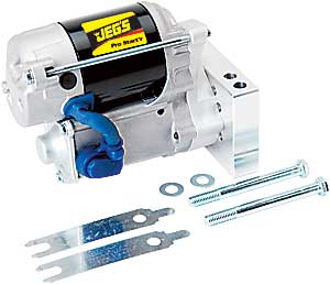
The wire I'm talking about is the blue S looking thing going from the solenoid to the motor. I'm going to install it like picture #1 in these instructions...
http://www.jegs.com/instructions/555.../555-10038.pdf
In their instruction it would have been helpful to actually write some directions like the powermaster site did rather than just showing pictures. Would have saved me some confusion.
Anyway, thanks for all the help. I think I finally have this all figured out. I knew the forum wouldn't let me down.
Actually I did a bunch more internet research and I found a really good explanation on how this is connected at the powermaster site.
I copied this from the following FAQ link from powermaster..
http://www.powermastermotorsports.com/faq-starter.html
"What do I do with the wire that went to the �R� terminal on the original starter?
In early original wiring harnesses, the �R� circuit was a ballast resistor bypass. This terminal is �no connection� when the starter is at rest, and is +12VDC while cranking.This circuit provided +12VDC to the ignition coil during cranking for easier engine starting. Cars that do not have a ballast resistor (i.e. HEI, MSD, or other aftermarket ignition systems) should not need this connection. In most cases, this wire can be eliminated. If the engine has no ignition during cranking, then the wiring of the coil is going to require an �R� terminal signal. To accomplish this, connect a 3A/400PIV diode (or Powermaster part # 600 ) in line with the MOTOR SIDE of the solenoid. (Note: This is the terminal on the solenoid which has the cable from inside the starter motor connected to it. It is opposite the BATTERY terminal on the solenoid. The cathode or banded end of the diode goes away from the starter. This allows current to go from the starter to the coil and yet not from the coil to the starter.)"
I do have a connection like this. There is a thick coated wire that runs from inside the solenoid housing to a lug on the motor part of the starter. I can attach it here. This wire should only be getting 12v when the motor is cranking, thus only sending 12v to the coil during cranking
My starter looks like very similiar to this one...
The wire I'm talking about is the blue S looking thing going from the solenoid to the motor. I'm going to install it like picture #1 in these instructions...
http://www.jegs.com/instructions/555.../555-10038.pdf
In their instruction it would have been helpful to actually write some directions like the powermaster site did rather than just showing pictures. Would have saved me some confusion.
Anyway, thanks for all the help. I think I finally have this all figured out. I knew the forum wouldn't let me down.

Melting Slicks
Joined: Dec 2005
Posts: 2,441
Likes: 0
I do have a connection like this. There is a thick coated wire that runs from inside the solenoid housing to a lug on the motor part of the starter. I can attach it here. This wire should only be getting 12v when the motor is cranking, thus only sending 12v to the coil during cranking
Last edited by shafrs3; Apr 15, 2007 at 11:07 AM.
Le Mans Master


Joined: Dec 2006
Posts: 8,837
Likes: 1,028