


Ballast resistor on a 73?
Thread Starter
Burning Brakes


Joined: Nov 2002
Posts: 952
Likes: 44
From: NC
I have a mallory magnetic breakerless distributor and the directions say that I need an ballast resistor in order to drop the amperage down. It is my understanding that a 73 corvette has a resistor WIRE that goes from the starter to the coil. I should not need both the ballast resistor and a resistor wire?
I think I am going to put the engine in, wire it up, and then put the amp meter on and check to see if they resistor wire dropped the amps down enough and if not, I will replace the resistor wire with a normal wire and install the ballast resistor. Any thoughts about this?
I think I am going to put the engine in, wire it up, and then put the amp meter on and check to see if they resistor wire dropped the amps down enough and if not, I will replace the resistor wire with a normal wire and install the ballast resistor. Any thoughts about this?
Racer


Joined: Aug 2003
Posts: 259
Likes: 2
From: Sacramento CA
The resistor wire will come from the ignition switch and drop the voltage down. With the key ON check the voltage at the coil. Should be 7-8 volts or so with a resistor wire. Resistor wire is visibly different. It is off-white color and has a woven cloth-like insulation.
The wire from the starter to coil is a bypass for starting and will give a full 12 volts when cranking.
The wire from the starter to coil is a bypass for starting and will give a full 12 volts when cranking.
Last edited by RPOL68; Aug 8, 2007 at 01:08 PM.
Melting Slicks

Joined: Mar 2006
Posts: 3,342
Likes: 7
From: Connecticut
You do not want to use two.
The '73 had it in line from the factory but if you want to test it heres the procedure.
"You can test your stock ignition system voltage while the engine is at idle at the coil (+) terminal. If the measured voltage is within 1-volt of battery voltage,an ignition ballast resistor must be installed in the wire from the ignition switch"
Race Director

Joined: May 2006
Posts: 16,528
Likes: 53
From: Dayton, Ohio
I would place a call to Mallory first.I dont think you will be able to detect a diff. in amp. or voltage on the resitance wire unless you set it up in a certain manner to read it.Did that make sense? PM 69427-I think Mike can help you if Mallory doesnt.
Edit-ok looks like you have a procedure to test.
Edit-ok looks like you have a procedure to test.
Last edited by ...Roger...; Aug 8, 2007 at 01:13 PM.
Tech Contributor
Joined: Jun 2004
Posts: 20,934
Likes: 962
From: I tend to be leery of any guy who doesn't own a chainsaw or a handgun.
I would place a call to Mallory first.I dont think you will be able to detect a diff. in amp. or voltage on the resitance wire unless you set it up in a certain manner to read it.Did that make sense? PM 69427-I think Mike can help you if Mallory doesnt.
Edit-ok looks like you have a procedure to test.
Edit-ok looks like you have a procedure to test.

A call to Mallory would be prudent. Ask them how much current the module can safely conduct. (It should be much more than the standard current that the points originally switched, letting you use the stock resistance and coil.) Given that they say to use a resistive wire in the coil circuit tells me that it is a simple (and electronically stupid
 ) electronic switch. Also, make sure that the Mallory rep tells you it is safe to operate (under long cranking, flooded sessions) with the starter solenoid bypass wiring intact.
 You are correct in your first post that the resistive wire limits the coil current. It does NOT regulate the coil voltage.
DW is correct in his measurement statement. You will get significantly different readings (of voltage or current) depending how you measure the circuit. As long as you understand what you are doing, then the measurements will make sense.
Good luck!
Racer
Joined: Aug 2003
Posts: 259
Likes: 2
From: Sacramento CA
James B is asking for a way to confirm that he does or does not have a resistor wire running to the coil. Testing the VOLTAGE at the coil + is an appropriate test.
Voltage produced by the coil is a product of the coil winding, core design, saturation period, and the triggering system.
Amperage or current flow is based on the load and really isn't a test factor here.
Ohm's law states that, in an electrical circuit, the current passing through a conductor between two points is proportional to the potential difference (i.e. voltage drop or voltage) across the two points, and inversely proportional to the resistance between them.
In mathematical terms, this is written as I=V/R, where I is the current in amperes, V is the potential difference in volts, and R is a constant, measured in ohms, called the resistance. The potential difference is also known as the voltage drop, and is sometimes denoted by E or U instead of V.
Melting Slicks
Joined: May 2007
Posts: 3,246
Likes: 4
From: Bay Area CA
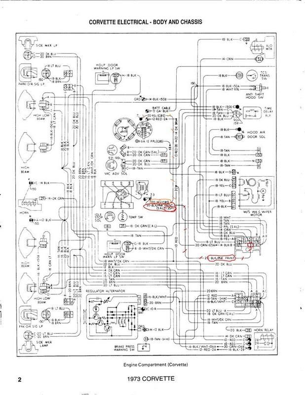
I have a '73 and upgraded my Dist to a HEI, so know all the parts involved. This wire needs to be bypassed on an HEI install. No offense to any one, but you have gotten some wrong info. The Resistor wire is Black with pink lettering that says "res wire 1.35 ohm" on it. It runs from the engine side of the wiring harness connector, to the + side of the coil. It is fed from the interior by a Red (really a med pink) regular 10 gauge wire into the pass comp side of the harness connector, and is fed by the ignition switch. The other, cloth sleeved wire at the + conn of the coil is a normal wire, cloth sleeved for heat protection, used to deliver full +12V to the coil for a hotter spark during cranking on start up. It is a to bypass the res wire and hooked to a tab the solinoid of the starter.
Your malory may reqiure a specific resistance to the coil. If this is the case, you may not be able to use the stock reisitance wire. first, get the resistance required by the Coil from mallory. Second, disconnect the reisitance wire (the black one with pink lettering) completly free, in the air, from the coil. Get a DVM, set it to resistance and with the ignition off, test the resistance from the free coil res wire to the "Gauges" fuse metal side 10A fuse, this is a common point. this will tell you the resistance of the resistance wire, and if it's in spec, you don't need to do any modifacations, you can use it.
If not you will need to bypass it with a regular 10 gauge wire in the pass compartment, like I did, and install a Ballast resistor in line with the new wire to the coil, preferably, in the engine compartment. You splice in to the Coil wire from the ignition switch in the pass compartment before it goes resistive, and run it into the engine compartment through a pluged hole which is available on the firewall. Install the ballst res, if needed in the engine compartment.
Or just get an HEI, if it fits your application, in which case you will need to run a bypass wire to the Batt side of the HEI, like I said, but w/o the ballast res.
Last edited by RunningMan373; Aug 9, 2007 at 08:04 PM.
Corvette Stories
The Best of Corvette for Corvette Enthusiasts

Every 2027 Corvette Engine Explained
Joe Kucinski
Designer Imagines A Corvette That Looks More Like a Corvette Than the Corvette
Verdad Gallardo
10 Ugly Corvettes That We Still Kinda Love
Joe Kucinski
Top 10 Most Expensive Corvettes Ever Sold on Bring A Trailer
Brett Foote
10 Things Every Corvette Owner Needs (2026 Edition)
Michael S. Palmer
8 Most "Only Corvette Owners Understand" Quirks and Problems
Pouria Savadkouei
10 Reasons the C6 Z06 is Still A Performance Benchmark After 20 Years
Joe Kucinski
How Much Horsepower Every Corvette Engine "LOST" in 1972
Joe Kucinski
Top 10 DOs and DON'Ts for Protecting Your Convertible Top!
Michael S. Palmer
Melting Slicks
Joined: Mar 2005
Posts: 2,838
Likes: 10
From: Austin TX
Running man,..you have it backwards. On 67-74E Chevys, the brown wire to the "+" side of the coil comes from the starter solenoid and is only hot when the key is in the "start" position. A full 12v is better for cold starts. The cloth insulated white wire, which also goes to the "+" side of the coil, is a resistor wire from the ignition switch that reduces volts from 12v~ to about 6-9v, which will allow points to live. This lost energy causes heat, hence the cloth insulation. And it's the reason for the "accessory" position for the key. If the engine is off but the key is on, this resistor wire can really heat up and burn up.
Most aftermarket ignition systems need a full 12v (but check with the manufacturer) so bypassing the resistor is best. I simply purhase a length of 14g white braided wire from Home Depot and run it from the "IGN" port on the fuse box to the coil (or box, or distributor, depending) for a full 12v.
Most aftermarket ignition systems need a full 12v (but check with the manufacturer) so bypassing the resistor is best. I simply purhase a length of 14g white braided wire from Home Depot and run it from the "IGN" port on the fuse box to the coil (or box, or distributor, depending) for a full 12v.
Melting Slicks
Joined: May 2007
Posts: 3,246
Likes: 4
From: Bay Area CA
Running man,..you have it backwards. On 67-74E Chevys, the brown wire to the "+" side of the coil comes from the starter solenoid and is only hot when the key is in the "start" position. A full 12v is better for cold starts. The cloth insulated white wire, which also goes to the "+" side of the coil, is a resistor wire from the ignition switch that reduces volts from 12v~ to about 6-9v, which will allow points to live. This lost energy causes heat, hence the cloth insulation. And it's the reason for the "accessory" position for the key. If the engine is off but the key is on, this resistor wire can really heat up and burn up.
Most aftermarket ignition systems need a full 12v (but check with the manufacturer) so bypassing the resistor is best. I simply purhase a length of 14g white braided wire from Home Depot and run it from the "IGN" port on the fuse box to the coil (or box, or distributor, depending) for a full 12v.
Most aftermarket ignition systems need a full 12v (but check with the manufacturer) so bypassing the resistor is best. I simply purhase a length of 14g white braided wire from Home Depot and run it from the "IGN" port on the fuse box to the coil (or box, or distributor, depending) for a full 12v.
Last edited by RunningMan373; Aug 9, 2007 at 08:04 PM.
Thread Starter
Burning Brakes
Joined: Nov 2002
Posts: 952
Likes: 44
From: NC
I put an OHM meter on the resistor wire tonight and it registered at 1.5 ohms which should be sufficient for my application. This is in range of the mallory ballast resistor that is recommended.
Thank you for yalls help....Im a mechanical engineering student and our teachers tell us that us ME students don't usually get this electrical stuff....They explain amps and voltage like water in a pipe. Voltage is your water pressure and amps is the amount of flow through the pipe If I remember correctly. I could be wrong I have only taken a basic electromagnetic physical forces class so far. Circuits is next semester.
Thank you for yalls help....Im a mechanical engineering student and our teachers tell us that us ME students don't usually get this electrical stuff....They explain amps and voltage like water in a pipe. Voltage is your water pressure and amps is the amount of flow through the pipe If I remember correctly. I could be wrong
I have only taken a basic electromagnetic physical forces class so far. Circuits is next semester.

Racer

Joined: Oct 2001
Posts: 412
Likes: 0
From: Monroe North Carolina
RunningMan373 Has hit the nail on the head. Took a look at the harness tonight that I have on garage floor with my buddy JamesB creator of this thread. Mine was black with pink letters (RESISTANCE DO NOT CUT) . A med pink wire on the other side of the fuse block.
Thanks Runningman373
Bobby
Thanks Runningman373
Bobby
Melting Slicks
Joined: May 2007
Posts: 3,246
Likes: 4
From: Bay Area CA
RunningMan373 Has hit the nail on the head. Took a look at the harness tonight that I have on garage floor with my buddy JamesB creator of this thread. Mine was black with pink letters (RESISTANCE DO NOT CUT) . A med pink wire on the other side of the fuse block.
Thanks Runningman373
Bobby
Thanks Runningman373
Bobby
Last edited by RunningMan373; Aug 9, 2007 at 04:55 AM.
Tech Contributor
Joined: Jun 2004
Posts: 20,934
Likes: 962
From: I tend to be leery of any guy who doesn't own a chainsaw or a handgun.
I put an OHM meter on the resistor wire tonight and it registered at 1.5 ohms which should be sufficient for my application. This is in range of the mallory ballast resistor that is recommended.
Thank you for yalls help....Im a mechanical engineering student and our teachers tell us that us ME students don't usually get this electrical stuff....They explain amps and voltage like water in a pipe. Voltage is your water pressure and amps is the amount of flow through the pipe If I remember correctly. I could be wrong I have only taken a basic electromagnetic physical forces class so far. Circuits is next semester.
Thank you for yalls help....Im a mechanical engineering student and our teachers tell us that us ME students don't usually get this electrical stuff....They explain amps and voltage like water in a pipe. Voltage is your water pressure and amps is the amount of flow through the pipe If I remember correctly. I could be wrong
I have only taken a basic electromagnetic physical forces class so far. Circuits is next semester.
I don't have any '73 specific electrical drawings, but your measurement looks correct. The coil primary system resistance for a points system should be in the neighborhood of about three ohms total (1.5 ohms from the resistance wire, and 1.5 ohms resistance in the coil primary winding), which will result in about four amps (peak) charging current.
Melting Slicks
Joined: May 2007
Posts: 3,246
Likes: 4
From: Bay Area CA
I put an OHM meter on the resistor wire tonight and it registered at 1.5 ohms which should be sufficient for my application. This is in range of the mallory ballast resistor that is recommended.
Thank you for yalls help....Im a mechanical engineering student and our teachers tell us that us ME students don't usually get this electrical stuff....They explain amps and voltage like water in a pipe. Voltage is your water pressure and amps is the amount of flow through the pipe If I remember correctly. I could be wrong I have only taken a basic electromagnetic physical forces class so far. Circuits is next semester.
Thank you for yalls help....Im a mechanical engineering student and our teachers tell us that us ME students don't usually get this electrical stuff....They explain amps and voltage like water in a pipe. Voltage is your water pressure and amps is the amount of flow through the pipe If I remember correctly. I could be wrong
I have only taken a basic electromagnetic physical forces class so far. Circuits is next semester.
Melting Slicks
Joined: Mar 2005
Posts: 2,838
Likes: 10
From: Austin TX
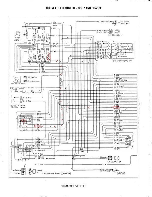
I can't see what's going on the the schmeatic above (too small) and perhaps Chevy quit using the cloth insulated wire and went to another color wire, but I stand by my dscription of the what/where the bypass wire is (the full 12v wire) and what/where the resistor wire is. Here's more:
http://www.pontiacstreetperformance....onversion.html
It is critical to understand that the HEI requires 12 volts AT ALL TIMES to work at it’s best, and points would burn up with 12 volts at all times, so the factory added either a inline ballast resistor or a resistance type wire that reduces the 12 volts from the battery down to around 9.3 volts to the coil. The points-type distributors do use 12 volts when cranking, however, this is accomplished with a 'bypass wire', located between the starter solenoid (R) terminal and the coil (+) terminal, and is 'hot' only in the ignition switch's 'crank' position and "bypasses" the resistor wire to supply the 12 volts. In other words, on some cars, there will be 2 wires for spark juice, one is 'hot' in the ignition switch "crank" position, the other is 'hot' in the ignition switch "run" position. This was common in the pre-1971 cars, which used an inline ballast resistor with an external voltage regulator.
From the FAQ of M&H: http://www.wiringharness.com/
"I want to install an H.E.I. distributor?
All original "point type" distributors require no more than 9.6 volts (approximately) to operate correctly. Most GM cars use a "white cloth covered" resistance wire or a "ballast resistor" to reduce the line voltage to the coil from 13.7 volts (approximately, when vehicle is running) to the necessary 9.6 volts (approximately). The "white cloth covered" resistance wire or a lead from a "ballast resistor" must not be used to power a GM H.E.I. distributor. This is a common mistake, that will degrade performance of the ignition system. All GM H.E.I. distributors require full system voltage of 13.7 volts (approximately, when vehicle is running) to operate at peak efficiency."
More from M&H:
http://www.breakerless.com/coil_instruction_sheets.pdf
Ballast Bypass – During cranking, the starter may pull the battery voltage down by several volts. To
compensate and allow the coil to develop sufficient voltage to fire the plugs, the ballast resistor is bypassed
when the key is in the start position. This is typically accomplished with a wire that connects between a terminal
on the starter solenoid and coil (+), but other methods may be employed.
This function may be checked attaching a test light between coil (+) and ground, and grounding the (-) terminal
of the coil. With the key in the RUN position, the test light should be at half brightness. When the key is turned to
the START position, the light should become brighter indicating the coil is receiving full battery voltage (i.e.,
ballast is being bypassed).
Last edited by 73, Dark Blue 454; Aug 10, 2007 at 02:17 PM.
Melting Slicks
Joined: May 2007
Posts: 3,246
Likes: 4
From: Bay Area CA
Melting Slicks
Joined: Mar 2005
Posts: 2,838
Likes: 10
From: Austin TX
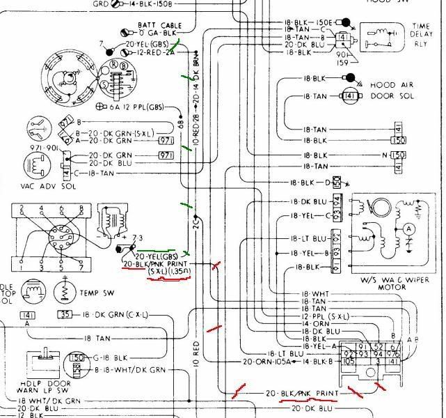
Ok, I can that schematic,..thanks. The wire marked by your red marks is the resistor wire from the ignition switch, which should provide 9v~ to the coil. The wire you've marked with green, is the bypass wire which provides a the full 12v for cranking. If it's cloth sleeved on 73's (it's always been a normal plastic sleeved brown or a burnt yellow color on previous Chevy's) I'm guessing the cloth is meant to keep it alive as it meanders around the hot exhaust. The cloth is keeping heat out, not insulating a resistor wire.
Racer
Joined: Aug 2003
Posts: 259
Likes: 2
From: Sacramento CA
I'm going to take a shot at saying we are confusing two different things, wire insulation and a heat protection sleeve.
If the wire is Yellow it has Yellow insulation. There can be, and apparently is, a SLEEVE over this yellow wire. Maybe (GBS) is a gray black sleeve? Who knows?
A resistor wire was commonly insulated with white cloth material in the 60's. It appears that the wire may have changed colors but the purpose has not.
Measure the voltage at the + terminal of the coil while running, should be around 9V with a resistor wire. If you need 12V, run another wire. Measure when cranking, should be close to 12V.
Melting Slicks
Joined: May 2007
Posts: 3,246
Likes: 4
From: Bay Area CA