


Power Lock Wiring

Instructor


Joined: Jul 2012
Posts: 171
Likes: 22
From: Kentucky
My new pigtails aren't lettered but from pictures it appears that the pigtail wires are in he right place. when i match the pins to the harness in the car all the colors match. not sure who i ordered pigtails and switches I believe Ecklers. at any rate when i plug the passenger side switch in the fuse blows. I tried what chrisNY did by taking one of the door ground wires to the black wire from drivers side and fuse held, actuator clicked but didn't work. when i tried driver side switch it blew the fuse. i think i am destined to manually unlocking my doors!
Racer
Joined: Jul 2012
Posts: 420
Likes: 3
From: deposit new york
if you got power, and your actuators work when your connect them to a 12v, then its gatta be a wiring thing, i know the the system had me pulling hair out, if its not perfect it will pop fuses. if it doesnt pop the fuse with everything connected and only pops when you try the switch, then try changing the grounds around on the pass side. one from the door to the bottem 2 pins, and the other from the door up to the 3 pin side. also the switches i got from ecklers sucked big time, i got generic ones from advanced, 10 times better. the first time i plugged in ecklers the pins sunk into the switch and shorted it out. i also took the wires out of the pigtails, and connected 1 at a time to find where i was having the problem, worked much better. i know i went threw about 20 fuses to figure it out.
Last edited by chrisNY; Sep 23, 2012 at 11:58 AM. Reason: new info
Instructor
Joined: Jul 2012
Posts: 171
Likes: 22
From: Kentucky
if you got power, and your actuators work when your connect them to a 12v, then its gatta be a wiring thing, i know the the system had me pulling hair out, if its not perfect it will pop fuses. if it doesnt pop the fuse with everything connected and only pops when you try the switch, then try changing the grounds around on the pass side. one from the door to the bottem 2 pins, and the other from the door up to the 3 pin side. also the switches i got from ecklers sucked big time, i got generic ones from advanced, 10 times better. the first time i plugged in ecklers the pins sunk into the switch and shorted it out. i also took the wires out of the pigtails, and connected 1 at a time to find where i was having the problem, worked much better. i know i went threw about 20 fuses to figure it out.
Racer
Joined: Jul 2012
Posts: 420
Likes: 3
From: deposit new york
take the wires out of the pigtails, that way you can move them around. mine did the same after i hooked them up close to right, but it was the pass side blowing the fuse drivers side was fine soon as i plug in pass side and tried it, pop another fuse. also which pin the black wire is going to (the one connected the doors) try that on the other bottem pin.
Racer
Joined: Jul 2012
Posts: 420
Likes: 3
From: deposit new york
Le Mans Master


Joined: Sep 2002
Posts: 5,236
Likes: 898
From: Myrtle Beach SC
So the answer is in 1978, Chevrolet published an 11 x 17 Corvette Electrical Troubleshooting Manual and it is great! Not only are there color-coded wiring schematics but describes the circuit operation while showing location of components. A tremendous resource for any 1978 owner.

I have picked up a couple both from swap meets and eBay so they seem to be plentiful.
Corvette Stories
The Best of Corvette for Corvette Enthusiasts

5 Best & 5 Worst Corvette Daily Drivers
Joe Kucinski
The Headlights of Every Corvette Generation Explained
Joe Kucinski
5 Best & 5 Most Overrated Corvette Track Packages of All Time!
Joe Kucinski
Every 2027 Corvette Engine Explained
Joe Kucinski
Designer Imagines A Corvette That Looks More Like a Corvette Than the Corvette
Verdad Gallardo
10 Ugly Corvettes That We Still Kinda Love
Joe Kucinski
Top 10 Most Expensive Corvettes Ever Sold on Bring A Trailer
Brett Foote
10 Things Every Corvette Owner Needs (2026 Edition)
Michael S. Palmer
8 Most "Only Corvette Owners Understand" Quirks and Problems
Pouria Savadkouei
7th Gear
Joined: Feb 2012
Posts: 7
Likes: 0
Hi
I have a bit of a problem with my power locks on my '78 vette. I've been debugging them this weekend but can't get them working 100%.
Problem is, on the passenger side (PS), when I hit the lock switch, not enough power gets sent to the actuators to move the locks as they should. My voltmeter reads only about 8 volts reaching the actuators when the PS switch is used, compared to about 12 volts when the Driver's side switch is used.
So, here's what I debugged:
From the PS switch, around 12 volts leave out of the pink and purple wires when I hit the PS switch. So far so good, and the switch is thus not the problem.
But, only about 8 of these 12 volts reach the pink and purple wires on the Driver Side. The remaining 4 volts are getting lost somewhere within the dash.
Using my acrobatic skills, I got under the dash on the driver's side. I could see the pink and purple wires coming in from the driver's door. But, I was surprised to see that they do not go directly to the pink/purple wires on the passenger side. Rather, they connect to two sets of wires that come out from under the dash. One set has a white wire and a green wire coiled around each other. The other set has a brown wire and a blue wire. The purple wire went to one of these sets, while the pink went to the other.
Has anyone noticed this? Why do the pink/purple wires on the Driver's side not go directly to the pink/purple wires on the passenger side? What are these two sets of wires for? (the white wire and green wire set, and the brown wire and blue wire set). Any tips on debugging where the voltage is getting lost?
Thanks
PJ
I got mine sorted. Heading out to get lock actuator servos now. Anyhows, just got most of my problems sorted due to this thread. Once I saw the schematics I could understand why when one lock switch goes bad they both quit working. I had a few more problems with Vet Vet.... :P So I made a video to go along with all this great information.

Heel & Toe
Joined: Jul 2023
Posts: 23
Likes: 7
Been dinking around a little
Attachment 48178584
Attachment 48178584
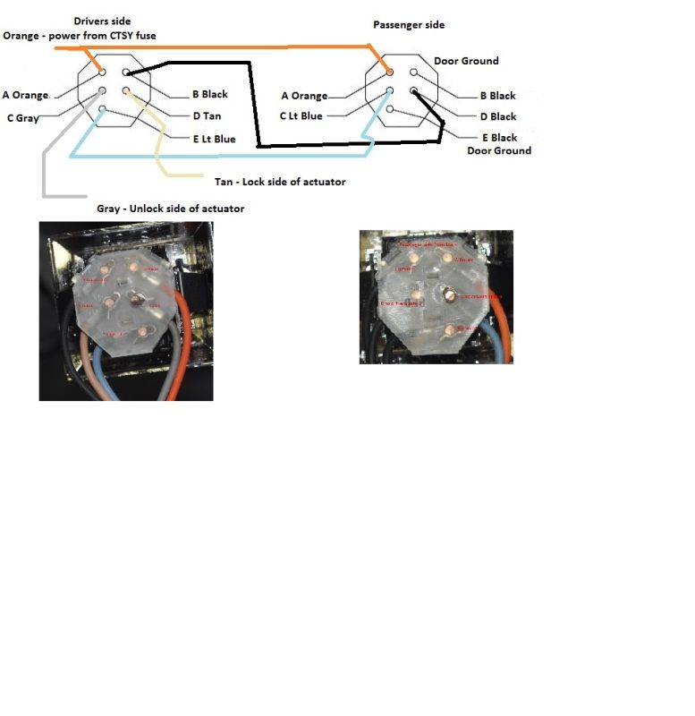
This image shows the pigtails and where the wires should go. Mine isn't working and I couldn't wrap my head around how (or why) it should work. If you flip the door lock switch over, the pins are the mirror image of the pigtail slots. Here's what I found with my multimeter.

switch at rest: continuity between B-D and between C-E
switch unlock: continuity between A-C
switch lock: continuity between A-D
With this it became easier for me to visualize what connections are being made with the pigtails in this diagram.