


82 Wiring Problem
Thread Starter
Racer

Joined: May 2007
Posts: 285
Likes: 0
From: Ga.
I am having a problem with several of my center gauges. My CEL light won't work. My alt. light won't come on before starting or after, but my voltmeter works. My low fuel light seems not to be working when the fuel is low or close to empty. I have checked the PCB for faults but I have not found any. I have checked all of the grounds and they appear to be ok. What gives? I am about ready to pull the dash out to look further. 
Any suggestions?

Any suggestions?
Race Director

Joined: May 2006
Posts: 16,528
Likes: 53
From: Dayton, Ohio
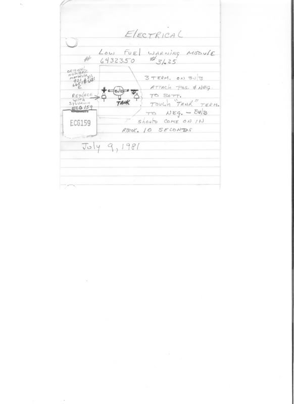
As far as the low fuel light the tank has to be very very low to come on.If you want to remove the module I can tell you how to test it outside the car.On your CEL can you apply 12v and a ground through the printed circuit and get the light to come on?Same with your Alt light?
Thread Starter
Racer
Joined: May 2007
Posts: 285
Likes: 0
From: Ga.
I think I have tried that. I am getting a voltage drop across the bulb, I just don't have any current. I tried to take my test light across it, but it want light up either! The black/pink wire is hot, but the brown wire to the ECM seems like its not completing the circuit. I think that the brown wire is part of the circuit for both lights. I am not getting continuity from the brown wire from the alternator back to the idiot light. The voltmeter must read votage from the battery and not from the alternator.
Thread Starter
Racer
Joined: May 2007
Posts: 285
Likes: 0
From: Ga.
I have the center cluster loose. I have already checked out the PCB and it appears to be good. Can I apply 12v across the bulbs without burning up the board. In otherwise how much current can it handle? I think my problem is elsewhere. I am about ready to pull the dash to get into the wiring harness. I'm not sure how hard that will be.
Corvette Stories
The Best of Corvette for Corvette Enthusiasts

8 Coolest Corvette Pace Cars (and Replicas) of All Time
Verdad Gallardo
Top 10 Corvette Engines RANKED by Peak Torque (70+ Years of Muscle!)
Joe Kucinski
Corvette ZR1X Will Be Pacing the Indy 500, And Could Probably Race, Too!
Verdad Gallardo
Top 10 Corvettes Coming to Mecum Indy 2026!
Brett Foote
Top 10 C9 Corvette MUST-HAVES to Fix These C8 Generation Flaws!
Michael S. Palmer
10 Revolutionary 'Corvette Firsts' Most People Don't Know
Joe Kucinski
5 Reasons to Upgrade to an LS6-Powered Corvette; 5 Reasons to Stay LT2
Michael S. Palmer
2027 Corvette vs The World: Every C8 vs Its Closest Competitor
Joe Kucinski
10 Most Common Corvette Problems of the Last 20 Years!
Joe KucinskiRace Director
Joined: May 2006
Posts: 16,528
Likes: 53
From: Dayton, Ohio
I have the center cluster loose. I have already checked out the PCB and it appears to be good. Can I apply 12v across the bulbs without burning up the board. In otherwise how much current can it handle? I think my problem is elsewhere. I am about ready to pull the dash to get into the wiring harness. I'm not sure how hard that will be.
Thread Starter
Racer
Joined: May 2007
Posts: 285
Likes: 0
From: Ga.
Can this be done at the pigtail coming from the fuel tank. ( 3 wires ) or does this need to be done at the fuel gage. You are saying take the positive to one side, negative to grd., & tank to ground and wait 10 sec..
Correct?
Correct?
Race Director
Joined: May 2006
Posts: 16,528
Likes: 53
From: Dayton, Ohio
No-that is the module with the bulb on the backside of the fuel gauge.Just turn 1/4 turn and it and the bulb will pop out.Lay it down with the bulb pointing up like the drawing.There are 3 contacts around the bulb.12volts to one- ground one -and then ground the center TANK contact to the grounded one and wait 10 seconds.
Burning Brakes


Joined: Jan 2006
Posts: 1,154
Likes: 1
From: St Augustine FL
I had a similar problem with my 82. The guages all worked but the oil pressure (seperate issue) None of the lights worked on the right hand side or the light that shines down on the AC/heater controls. I replaced the printed circuit board and made sure the gauge cluster harness connector was seated properly and presto every worked. There is also one fuse that controls the majority of the center gauges. Check it ( I am am sure you have) for the sake of double checking.
Thread Starter
Racer
Joined: May 2007
Posts: 285
Likes: 0
From: Ga.
Ok, I found the problem with my alternator light. The brown wire that comes from the alternator had been cut in two. Maybe thats why somebody had spliced in a new plug to the alternator. By looking at the schematic, I think the brown wire goes to the bulkhead connector ( 25 )to the fuse box. I could not find a wire going into it. So I pulled the harness connector loose and there is not a spade connector there. Anyway after finding this I went ahead and pulled the dash to get the fuse panel loose to get better access to look further. For some reason there is still quite alot of resistance to the wire from the fuse box to the center console connector. I will continue to look further to see what else might be wrong. Did the factory put in a kill switch under the passenger side of the dash attached to the AC duct?
Anyway after finding this I went ahead and pulled the dash to get the fuse panel loose to get better access to look further. For some reason there is still quite alot of resistance to the wire from the fuse box to the center console connector. I will continue to look further to see what else might be wrong. Did the factory put in a kill switch under the passenger side of the dash attached to the AC duct?
Thread Starter
Racer
Joined: May 2007
Posts: 285
Likes: 0
From: Ga.
New update,
The brown wire that come from the firewall that goes to the alt light has a resistor in it. Circuit 25. It must be bad. I am reading 1.5 meg ohms across it. I can not tell the resistance on it due to some heat damage. Does anyone have a clue? Does anyone have a schematic that shows this circuit?
Help!
Race Director
Joined: May 2006
Posts: 16,528
Likes: 53
From: Dayton, Ohio
New update,
The brown wire that come from the firewall that goes to the alt light has a resistor in it. Circuit 25. It must be bad. I am reading 1.5 meg ohms across it. I can not tell the resistance on it due to some heat damage. Does anyone have a clue? Does anyone have a schematic that shows this circuit?
Help!
The brown wire that come from the firewall that goes to the alt light has a resistor in it. Circuit 25. It must be bad. I am reading 1.5 meg ohms across it. I can not tell the resistance on it due to some heat damage. Does anyone have a clue? Does anyone have a schematic that shows this circuit?
Help!
Melting Slicks

Joined: Jul 2005
Posts: 2,740
Likes: 3
From: Aurora Ontario
I don't see anything on the brown either. The book refers to a 40 ohm resister which draws current and makes the warning light glow. The resister is in the generator.The test hole is in the rear of the generator.
Possible the previous owner or someone put a resister in line to make up a short fall in the 40 ohm internal resistor??
Basically brown comes out goes to the warning light via the printed circuit board. Pink comes out and goes to the 20 amp gage fuse.
Jim
Possible the previous owner or someone put a resister in line to make up a short fall in the 40 ohm internal resistor??
Basically brown comes out goes to the warning light via the printed circuit board. Pink comes out and goes to the 20 amp gage fuse.
Jim
Thread Starter
Racer
Joined: May 2007
Posts: 285
Likes: 0
From: Ga.
I think this is a factory resistor. The wiring harness had the factory tape still on it, and the connection to the resistor looked to be a factory type connection. I think that this resistor is there to protect the small PCB on the alt. warning light, probably to limit current to it. I don't know what year this might have started.. There is no one that I can find that has a schematic showing this resistor.
Race Director
Joined: May 2006
Posts: 16,528
Likes: 53
From: Dayton, Ohio
I think this is a factory resistor. The wiring harness had the factory tape still on it, and the connection to the resistor looked to be a factory type connection. I think that this resistor is there to protect the small PCB on the alt. warning light, probably to limit current to it. I don't know what year this might have started.. There is no one that I can find that has a schematic showing this resistor.
Thread Starter
Racer
Joined: May 2007
Posts: 285
Likes: 0
From: Ga.
I was told by Lectric Medic that circuit 25 is a resistance circuit to control the current from the alt. light to the alternator. They say that they have never seen a resisitor in the circuit, but it is possible. Can anyone measure this circuit to get me in the ballpark.