


electric fans
Pro


Joined: Aug 2006
Posts: 649
Likes: 8
From: COOKEVILLE TN
I Bought A Taurus Fan Off E-bay A While Back, Thought It Was A Mark Viii ( That's A Different Story ) My Question Is What Do I Need To Do To Get It Working, I Already Have An Electric And A Relay, '73 350 With 400th, It Wants To Get Hot In Heavy Traffic............i'm A Fair Shadetree, But Not That Good In The Electric Dept.............by The Way, Timing And Everything Is Right. Thanks !
7t3 In 10ec
7t3 In 10ec
Team Owner

Joined: Aug 2006
Posts: 24,125
Likes: 15
From: Columbia Missouri
I Bought A Taurus Fan Off E-bay A While Back, Thought It Was A Mark Viii ( That's A Different Story ) My Question Is What Do I Need To Do To Get It Working, I Already Have An Electric And A Relay, '73 350 With 400th, It Wants To Get Hot In Heavy Traffic............i'm A Fair Shadetree, But Not That Good In The Electric Dept.............by The Way, Timing And Everything Is Right. Thanks !
7t3 In 10ec
7t3 In 10ec
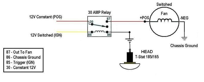
Use this diagram, and this T-stat. Basically you are powering the relay from the alternator. You are triggering the relay with a switched IGN source like the yellow wiper motor wire, or the ACC slot in your fuse panel. The power from the relay goes to the fan power wire, and you ground the fan to the frame or engine.
Now, the relay needs a ground, and this is where the T-stat switch comes in. Mount this switch in the passenger side head, opposite where the temp sending unit is on the driver's side. It is a temp switch, that uses the engine as a ground. When the temp is low, there is no connection so the switch has no ground. When the temp is high, the switch connects to the ground through the block giving the relay a ground so the fan turns on.
T-stat switch:
http://store.summitracing.com/partde...5&autoview=sku
Diagram:
Pro
Joined: Aug 2006
Posts: 649
Likes: 8
From: COOKEVILLE TN
Use this diagram, and this T-stat. Basically you are powering the relay from the alternator. You are triggering the relay with a switched IGN source like the yellow wiper motor wire, or the ACC slot in your fuse panel. The power from the relay goes to the fan power wire, and you ground the fan to the frame or engine.
Now, the relay needs a ground, and this is where the T-stat switch comes in. Mount this switch in the passenger side head, opposite where the temp sending unit is on the driver's side. It is a temp switch, that uses the engine as a ground. When the temp is low, there is no connection so the switch has no ground. When the temp is high, the switch connects to the ground through the block giving the relay a ground so the fan turns on.
T-stat switch:
http://store.summitracing.com/partde...5&autoview=sku
Diagram:
DON'T I NEED TO UPGRADE TO A LARGER ALTERNATOR FIRST?
Team Owner
Joined: Aug 2006
Posts: 24,125
Likes: 15
From: Columbia Missouri
It's a good idea but there are guys with electric fans and a stock alt.
Here, this may help you with the alternator upgrade. It's not expensive, and relatively easy.
http://photos.imageevent.com/durango...%20Install.pdf
Race Director

Joined: Dec 2007
Posts: 14,345
Likes: 4
From: Hartselle AL
St. Jude Donor '09
I just installed a Taurus fan I got from DB. I bought a e-fan wiring kit from the local Advanced Auto Parts which included all the wires, relay and a radiator probe. After installing, it worked fine except was not happy with the probe as it is not an accurate water temp. reading as it relies on conductive heat transfer from the radiator fins. This means the engine actually runs a bit hotter than the 185* turn on temp.
Today I went and got a "modern" switch that I put into the thermostat housing in place of the vacuum thermo switch (I've removed my AIRS system) so it was a perfect place. If you can't use that, OReilleys has a thermostat housing with 2 threaded holes, the second can be used for the fan switch.
Hope this helps.
Le Mans Master


Joined: Dec 2006
Posts: 5,557
Likes: 9
From: Oquirrh Mountains
St. Jude Donor '09
I Bought A Taurus Fan Off E-bay A While Back, Thought It Was A Mark Viii ( That's A Different Story ) My Question Is What Do I Need To Do To Get It Working, I Already Have An Electric And A Relay, '73 350 With 400th, It Wants To Get Hot In Heavy Traffic............i'm A Fair Shadetree, But Not That Good In The Electric Dept.............by The Way, Timing And Everything Is Right. Thanks !
7t3 In 10ec
7t3 In 10ec
The following was made for a '66, but the core height is the same for yours so it will work just as well.
Materials:
Get two 22" long 2"x2"x 1/8" aluminum angle pieces.
8 - #6x3/8" machine screws with flat (not pan) heads
2 - #6x1/2" machine screws with flat heads.
10 - 6" nuts & washers.
Automotive weatherstripping. I used a combination of 1/4" thick x 3/4 wide and 3/8" thick and 3/4" wide. 1/2" wide would have worked better, but the hardware store was out.
3/16" drill bit
masking tape
12 or so Aluminum pop rivets.
Place angles on radiator making sure they are snug against the hat. Drill five holes ~ 5/32 along top and bottom of plasic shroud - see photo below. Place drilled shroud on angles and mark the holes on the angles. Remove angles and drill holes corresponding to the shroud. Flip them over and carefully countersink the holes so the heads of the screws are not protruding above the aluminum. Be careful and don't go too deep or you will open up the hole and the screw will pull through.
Bolt up the angles and shroud by hand for a test fit. If ok, mark the angles inside the fan area for trimming.
I used a jigsaw with metal cutting blade to remove the marked area per above. Reassemble the angles and shroud for a final test fit. If ok, place weatherstripping along sides of shroud to seal any air leaks and to get the angle brackets 1/2" or so off of the core. It will look something like this when you are done.
To attach the angles to the radiator take the 3/16 bit and wrap the masking tape around he bit ~1/4 from the tip about 1/8" thick. This will act as a stop and prevent you from inadvertently drilling into the core when the bit breaks through. Mark six evenly spaced holes along the top/bottom of the brackets. Using a clamp(s) (soft jaws/scrap of wood between clamp and rad.) compress the shroud assembly 1/8 inch or so to help seal and hold weatherstripping in place against radiator. CAREFULLY drill the marked holes and rivet the radiator and shroud assembly together. It will look about like this when you are done (It isn't riveted yet in this image):
Good Luck,
-Lurkin
Last edited by Ben Lurkin; Feb 28, 2008 at 12:32 AM.
Burning Brakes


Joined: Jul 2006
Posts: 1,047
Likes: 12
From: SoCal
Use this diagram, and this T-stat. Basically you are powering the relay from the alternator. You are triggering the relay with a switched IGN source like the yellow wiper motor wire, or the ACC slot in your fuse panel. The power from the relay goes to the fan power wire, and you ground the fan to the frame or engine.
Now, the relay needs a ground, and this is where the T-stat switch comes in. Mount this switch in the passenger side head, opposite where the temp sending unit is on the driver's side. It is a temp switch, that uses the engine as a ground. When the temp is low, there is no connection so the switch has no ground. When the temp is high, the switch connects to the ground through the block giving the relay a ground so the fan turns on.
T-stat switch:
http://store.summitracing.com/partde...5&autoview=sku
Diagram:
Now, the relay needs a ground, and this is where the T-stat switch comes in. Mount this switch in the passenger side head, opposite where the temp sending unit is on the driver's side. It is a temp switch, that uses the engine as a ground. When the temp is low, there is no connection so the switch has no ground. When the temp is high, the switch connects to the ground through the block giving the relay a ground so the fan turns on.
T-stat switch:
http://store.summitracing.com/partde...5&autoview=sku
Diagram:

Corvette Stories
The Best of Corvette for Corvette Enthusiasts

Top 10 Most Expensive Corvettes Ever Sold on Bring A Trailer
Brett Foote
10 Things Every Corvette Owner Needs (2026 Edition)
Michael S. Palmer
8 Most "Only Corvette Owners Understand" Quirks and Problems
Pouria Savadkouei
10 Reasons the C6 Z06 is Still A Performance Benchmark After 20 Years
Joe Kucinski
How Much Horsepower Every Corvette Engine "LOST" in 1972
Joe Kucinski
Top 10 DOs and DON'Ts for Protecting Your Convertible Top!
Michael S. Palmer
Top 10 Most Explosive Corvettes Ever Made: Power-to-Weight Ratio Ranked!
Joe Kucinski
150 hp to 1,250 hp: Every Corvette Generation Compared by the Specs That Matter
Joe Kucinski
8 Coolest Corvette Pace Cars (and Replicas) of All Time
Verdad GallardoTeam Owner
Joined: Aug 2006
Posts: 24,125
Likes: 15
From: Columbia Missouri
This may be picky, but if you're using the alternator to provide power to lug 30, then you aren't providing "constant power" as your diagram is indicating. Don't get me wrong - what you're doing is fine, but your diagram is wrong based on how you say you wired the relay. And, you could in fact wire lug 30 to true constant power off of, say, the horn relay if you want (that's how mine is wired). Just sayin'...
Why wouldn't the BAT terminal on the alt be 12V constant? It's always hot even when the engine is off.
Burning Brakes
Joined: Jul 2006
Posts: 1,047
Likes: 12
From: SoCal
Racer

Joined: Apr 2007
Posts: 443
Likes: 0
From: Rexton New Brunswick
What year was the Focus?
looks like an awesome setup. I just bought the March Performance underdrive system and need to do the electric fan thing. As usual, you seem to have come up with a very sensible plan.
Cheers
Bill
Burning Brakes
Joined: Sep 2006
Posts: 1,071
Likes: 86
From: Rotonda FL
I believe that Durango Boy was banned from the forum some while ago. However, if you use the search function for looking for Focus fans, I believe you will find the information you are looking for.
Racer
Joined: Apr 2007
Posts: 443
Likes: 0
From: Rexton New Brunswick
I guess it pays to stop in every now and again. I had no idea. I spend the summer in the vette and the winter on here

Thanks