
Project: 2.375" Crossfire Throttle Bodies on an Offenhauser Cross RAM
 05-11-2008, 07:15 AM
#21
Instructor

Thread Starter

Some more progress.
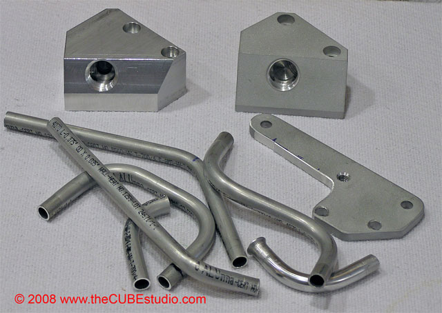
Just converting mock ups into real parts. Once I have the parts done, I can do the final assembly.
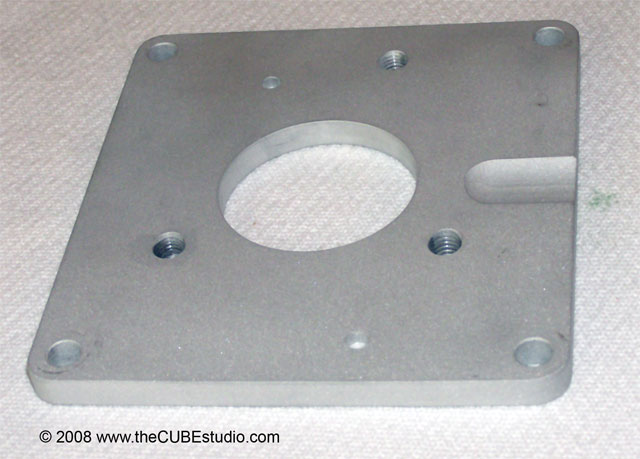
Here is the adapter plate for the TB. Note the clearance cut for the linkage arm. This is typical of the unexpected little (and sometimes big) problems you run into.
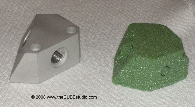
The fuel return 'Y' block along side the mock up piece:
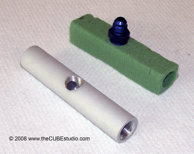
Fuel rail with its mock up:
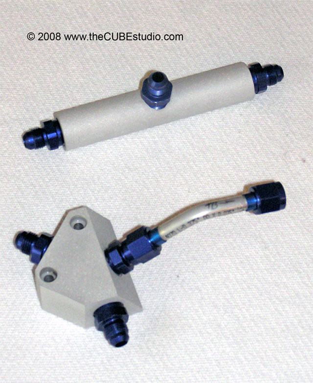
So these are the new fuel system pieces with the fititngs installed. Now I can start the final assembly:
Just converting mock ups into real parts. Once I have the parts done, I can do the final assembly.
Here is the adapter plate for the TB. Note the clearance cut for the linkage arm. This is typical of the unexpected little (and sometimes big) problems you run into.
The fuel return 'Y' block along side the mock up piece:
Fuel rail with its mock up:
So these are the new fuel system pieces with the fititngs installed. Now I can start the final assembly:
 05-14-2008, 03:04 PM
#22
Instructor
Thread Starter
Progess on the setup has progressed.
Here are the last couple of parts that I fabbed to mount the 'Y' block, fuel rail, and throttle cable bracket:
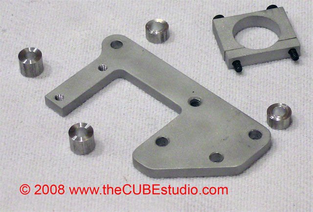
Goes together like this:
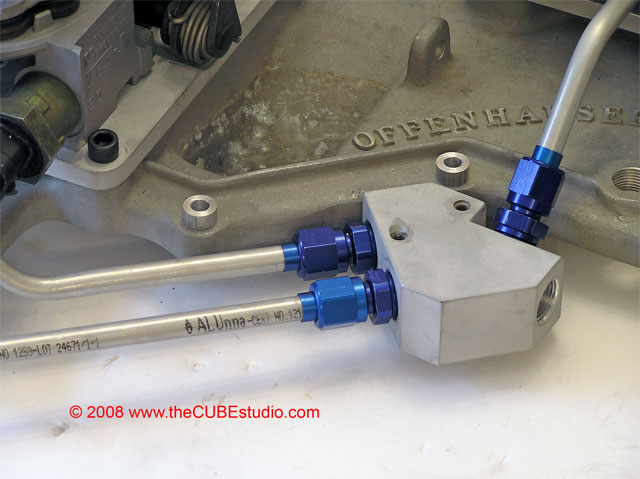
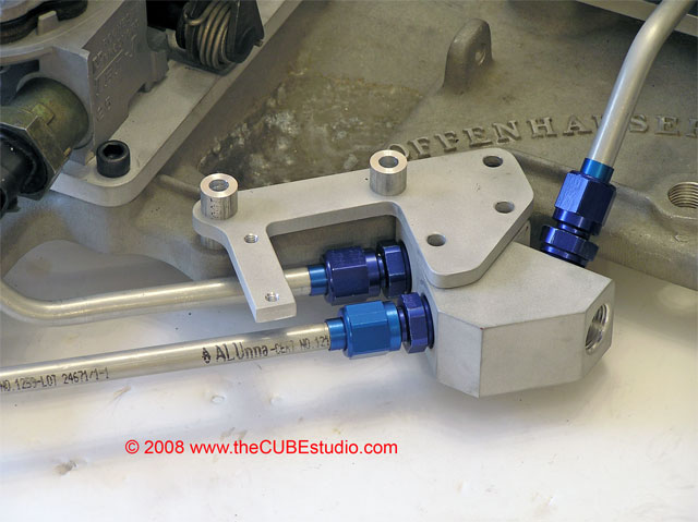
And the completed assembly looks like this. Both the supply and retun lines were moved down significantly. I've been thru the wrench clearance checks and stuff like that. The system is maintainable and even the IAC motor can be changed out now without pulling the fuel system apart.
Clearance issues with the valve cover and throttle cable have been resolved.
There are a few minor details to address. I am going to make a more robust fuel rail mount as I'm not satisfied with the one pictured.
I have to do a final mount of the TBs and then balance them. Next build up the injector pods and pressure test the whole system.
Then the whole assembly gets shipped to its owner who will be doing the install and air cleaner. That should be interesting to watch also!
Here are the last couple of parts that I fabbed to mount the 'Y' block, fuel rail, and throttle cable bracket:
Goes together like this:
And the completed assembly looks like this. Both the supply and retun lines were moved down significantly. I've been thru the wrench clearance checks and stuff like that. The system is maintainable and even the IAC motor can be changed out now without pulling the fuel system apart.
Clearance issues with the valve cover and throttle cable have been resolved.
There are a few minor details to address. I am going to make a more robust fuel rail mount as I'm not satisfied with the one pictured.
I have to do a final mount of the TBs and then balance them. Next build up the injector pods and pressure test the whole system.
Then the whole assembly gets shipped to its owner who will be doing the install and air cleaner. That should be interesting to watch also!
05-14-2008, 03:51 PM
#23
Racer

Hey 36, your work is excellent! You take detailing to a new level. I was just wondering, are throttle bodies programmable? With the increased CFM, there will be a huge jump in power, do you have to have a PMS?
05-15-2008, 08:24 AM
#24
Instructor
Thread Starter
USALT1:
This setup is over 1,000 CFM and uses 90 lb GM injectors from a 454 TB. Injectors can run at 23-28psi and at that level, this induction setup can support 500 HP.
The owner will have to tune the setup. My job in these projects is to get the harware ready to rock. I know how to move enough fuel and air to support the performace target I'm given, but I'm not a tuning expert.
My days of racing and spitting expensive parts out the oil pan and thru the hood are long over, and all of my performace and classic cars are gone now. I just have my wife's bone stock '82 Collector Edition Vette to take care of which needs no tuning. I get my hot rodding fix these days vicariously thru others who bring me projects like this one.
We've been talking about EBL as a possible tuning avenue. If the owner goes with that setup for tuning, I can hook him up with a very sharp guy to get the new 406 motor running strong. At that point I just kick back and


 05-29-2008, 01:31 AM
#26
Instructor
Thread Starter
Soon . .
Right now the setup is completely disassembled and the pieces are getting their final finishes and I'm doing some small alterations like the fuel rail mount and replacing some mock-up bolts with the final larger pieces.
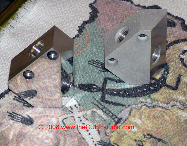
For example, here is the final supply rail mount (more robust) and the final pieces for the return 'Y' block


I made up aluminum spacers for the injector pods as they need to be spaced up to restore the relationship between the injector spray cone and the throttle plate and bore wall with the larger bore. The space up calcs to around 3/8" and I don't like the idea of stacking three fiber gaskets, so I use a 1/4" aluminum plate and then a single gasket.

Throttle shaft is out because I had to measure to machine clearance in the adapter plate for the return spring on the shaft arm . . just one of those things you run into.
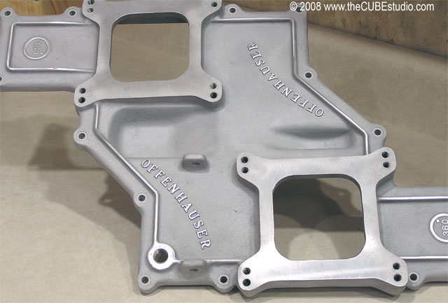
I blasted the manifold to get off the corrosion you can see in the earlier pictures, especially in the carb linkage pockets. Mr. Offy is purdy now.
I will be starting the final buildup soon and will be posting lots of pics of each step. It is a pretty awesome project.
Right now the setup is completely disassembled and the pieces are getting their final finishes and I'm doing some small alterations like the fuel rail mount and replacing some mock-up bolts with the final larger pieces.
For example, here is the final supply rail mount (more robust) and the final pieces for the return 'Y' block
I made up aluminum spacers for the injector pods as they need to be spaced up to restore the relationship between the injector spray cone and the throttle plate and bore wall with the larger bore. The space up calcs to around 3/8" and I don't like the idea of stacking three fiber gaskets, so I use a 1/4" aluminum plate and then a single gasket.
Throttle shaft is out because I had to measure to machine clearance in the adapter plate for the return spring on the shaft arm . . just one of those things you run into.
I blasted the manifold to get off the corrosion you can see in the earlier pictures, especially in the carb linkage pockets. Mr. Offy is purdy now.
I will be starting the final buildup soon and will be posting lots of pics of each step. It is a pretty awesome project.
05-29-2008, 10:28 AM
#27
Safety Car


NICE WORK!!!! Are you doing all this on a milling machine or a CNC? What do you charge to hog out a set of TBs with the good stuff (sealed SS bearings, HF injectors, ect...) I have a spare Crossfire set up and a 406 on the stand. Just kicking around ideas
05-30-2008, 10:11 AM
#28
Instructor
Thread Starter
I'll let you know that UltraMod Throttle body sets are expensive. I'm only going to make 2.125" and 2.375" from now on. No more 2". I'm really not interested in messing with stock motors.
All UltraMod TBs have functional balance ports. All vac ports and IAC are also functional. Sealed SS ball bearing shafts. Pod spacers and longer SS pod bolts and new SS idle stop screw. Clear coated.
I don't supply 454 injectors. It took myself and a buddy looking for several months to find three sets for projects. Only one set was genuine GM and that set is going on this Offy project. I paid a stupid amount of money for the whole TB just to get the injectors out of it.
If you want me to build you an Offy setup like this, you can have the last set of 90lb injectors that I have, but they are not GM. I have tested them and they ARE 90lb and they match flow wise. They are not for sale otherwise.
A crossfire is not appropriate for a 406 unless it is very highly modified . . as in adding material to the runners and then porting over that to relieve restrictions. I can do it, but it would cost you more than a new Offy and still not offer the performance or
 of the Offy.
You might be interested in my next project too. I am putting a set of 2.125" UltraMod TBs on an old 1960's in-line dual quad single plane manifold.
Email me directly to talk prices. If I put a price in a post, some forums get upset because it's considered advertising.
06-06-2008, 07:36 AM
#29
Instructor
Thread Starter
Finishing up the last couple of items before beginning final assembly.
The Offy lid got a bit of a face lift with the lettering brought back to bright silver.

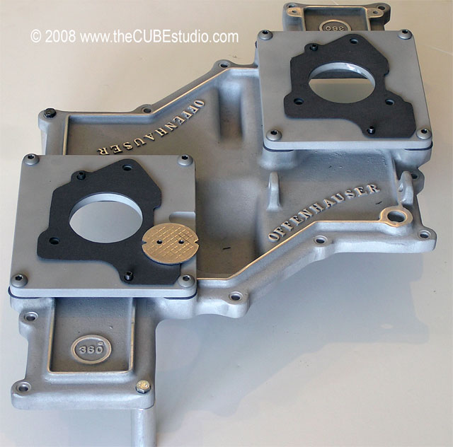
One of the many details is the pressure taps for gages or senders. Each injector pod is individually adjustable for pressure so a gage is needed in each pod.

I'm not personally in favor of permanent mechanical fuel pressure gages under the hood of a street car, so I use schrader valves for a quick hook up of a gage to set/check fuel pressure.
The best setup, in my opinion, is a sender under the hood with and electronic gage in the dash. It's a little pricey, but it is a safe setup and you can monitor the fuel pressure at high RPM and WOT where it actually matters.
With any luck, I'll be doing the final assembly this weekend, so watch for lots of pictures of that.
The Offy lid got a bit of a face lift with the lettering brought back to bright silver.
One of the many details is the pressure taps for gages or senders. Each injector pod is individually adjustable for pressure so a gage is needed in each pod.
I'm not personally in favor of permanent mechanical fuel pressure gages under the hood of a street car, so I use schrader valves for a quick hook up of a gage to set/check fuel pressure.
The best setup, in my opinion, is a sender under the hood with and electronic gage in the dash. It's a little pricey, but it is a safe setup and you can monitor the fuel pressure at high RPM and WOT where it actually matters.
With any luck, I'll be doing the final assembly this weekend, so watch for lots of pictures of that.
07-30-2008, 10:21 AM
#30
Instructor
Thread Starter
OK here is the final assembly photos. Sorry it took so long.
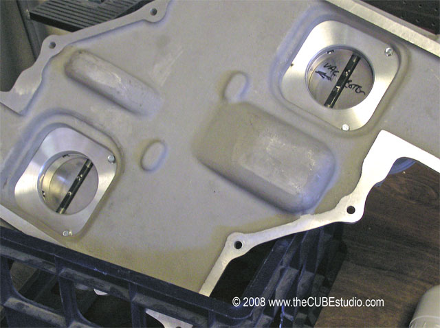
Owner requested the whole fuel system be moved down and sent this sketch:
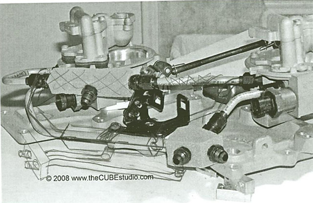
So, I took a deep breath and asked for a photo showing how much space I had below the rim of the lid and got this back (I added the red line):
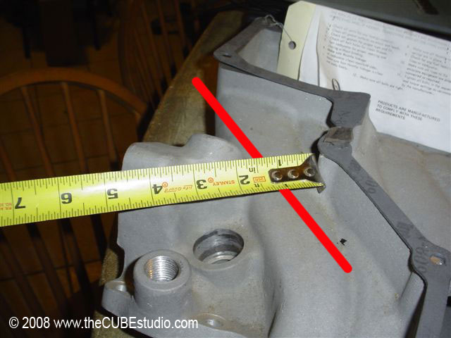
The redesign resulted in these parts getting the axe:
Note that the 'Y' block had already been replaced once due to an SFU (Simpson Foul Up) so I just played around blinging up the old one.
Owner requested the whole fuel system be moved down and sent this sketch:
So, I took a deep breath and asked for a photo showing how much space I had below the rim of the lid and got this back (I added the red line):
The redesign resulted in these parts getting the axe:
Note that the 'Y' block had already been replaced once due to an SFU (Simpson Foul Up) so I just played around blinging up the old one.
07-30-2008, 10:25 AM
#31
Instructor
Thread Starter
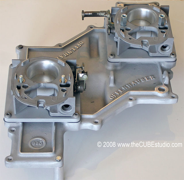
So after a fuel system redesign and making the new parts, it was time to start the final assembly. But that lid . . . not purdy enough . . so bling that up a bit:
The thing was rockin' and rollin' all over the place, so I made up some little legs to sit it on and got started by torqueing down the adapter plates. The gaskets had to be re-cut for the huge bore . . note the stock throttle plate for comparison:
Next comes the Mother Of All Throttle Bodies 2.375" 1,100 CFM :partyon: :
The Injector pods have to be spaced up to restore the proper relationship between the injector cone, the throttle plate and the bore wall. Calculations showed I needed another 1/4" and I don't like stacking that make gaskets to gether, so I made up aluminum spacers.
The spacers required longer bolts and also machined clearance for the fuel fittings . . . (detailed in earlier posts). Progress at this point:
07-30-2008, 10:26 AM
#32
Instructor
Thread Starter
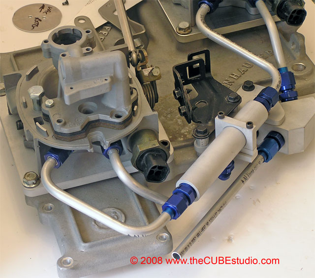
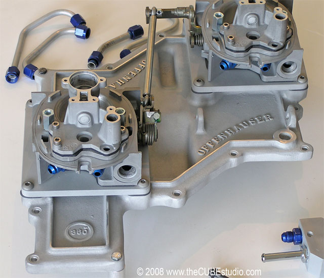
Hanging any weight (or stress) on aluminum tubing in vibration is a definate engineering no-no, so solid mounts have to be provided to keep the hose/braid used for the tie-ins from stressing the tubing. These are the mounts for the return 'Y' block and the supply rail. The throttle/cruise cable bracket is also incorprated into the mounting setup. The stock crossfire bracket has an odd hole in the base because I 'borrowed' it from my 'BIG TB' project to do the design:
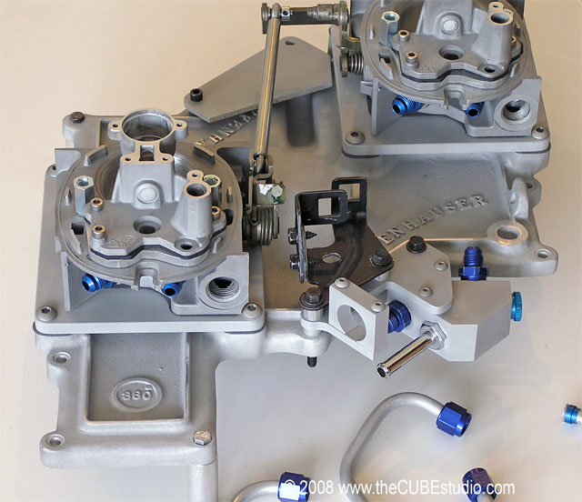
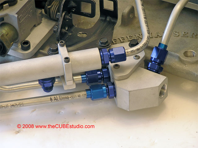
Put together the return lines. I've been engineering prototypes for a long time, so I learned very early to make sure things on paper can actually be built . . things like wrench clearance will come back to haunt you if you don't keep that in your brain as a criteria right from the get-go:
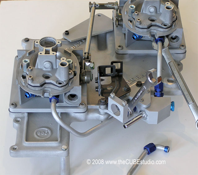
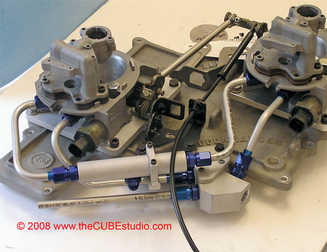
And finally the supply side. The original schedule on this project was 6 months to a year, but I only had it for two months. The owner's plans changed and he needed it back way early, so I did not have time to put the injectors in. I actually found genuine GM 90# injectors for this project! A few weeks after this project shipped, I finished developing pressure taps for the pod covers and a new regulator spring which goes from 15.5 to 30 lbs. These developments made it into my next project (bored TBs on an in-line dual quad manifold - see the new thread for that one), but were not ready for this Offy project, so this is how she shipped out:
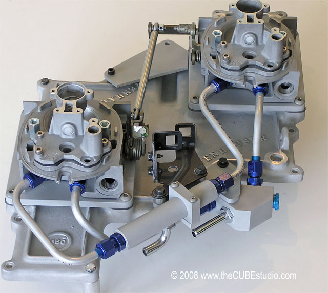
The unfished plate at the back of the manifold ios the mount for the Trans TV cable bracket. The owner is goung to position the bracket optimally during the install and then trim the plate to match.
Put together the return lines. I've been engineering prototypes for a long time, so I learned very early to make sure things on paper can actually be built . . things like wrench clearance will come back to haunt you if you don't keep that in your brain as a criteria right from the get-go:
And finally the supply side. The original schedule on this project was 6 months to a year, but I only had it for two months. The owner's plans changed and he needed it back way early, so I did not have time to put the injectors in. I actually found genuine GM 90# injectors for this project! A few weeks after this project shipped, I finished developing pressure taps for the pod covers and a new regulator spring which goes from 15.5 to 30 lbs. These developments made it into my next project (bored TBs on an in-line dual quad manifold - see the new thread for that one), but were not ready for this Offy project, so this is how she shipped out:
The unfished plate at the back of the manifold ios the mount for the Trans TV cable bracket. The owner is goung to position the bracket optimally during the install and then trim the plate to match.
07-30-2008, 10:27 AM
#33
Instructor
Thread Starter
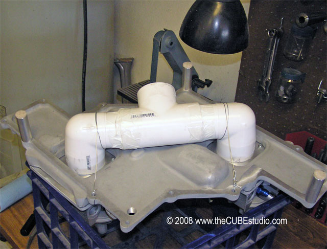
Throwing a bunch of harware together is one thing. But making sure it performs as designed is the last step in any good project. I do a lot of work with crossfire throttle bodies and I have a bench setup to balance them on the crossfire lid . . but this ain't no little crossfire . . .
After staring at that for a while, I decided that a couple of machined PVC adapters and some strapping tape made the mods needed to hook up to the big ol' Offy:
Once that setup was running, I could tame the beast. Everyone has their own opinion on this, but MY opinion is that any multi carb setup MUST be balanced properly, so the ability to properly balance MUST be designed in. All of my TB's, even these MOATBs have functional balance ports. It required some delicate micro machining to cut the ports into the sleeves, but let's see if the effort was worthwhile:
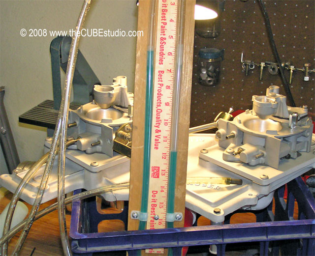
6" on the manometer, just like the Dr. (General Motors) ordered, and she's VERY sensitive with a slow and predictable reaction to the idle stop screw.
All of the effort boils down to this last piece of the pie . . must achive balance, grasshopper:
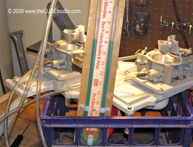
That's a live shot. Even more important than the static balance is the behavior with throttle movement. I've seen plenty of setups that balance out at idle, but as soon as you touch the throttle, they go wildly out of sync . . (the dreaded crossfire stumble).
Maximum deviation on Mr. Offenhauser is less than 1" total from idle to WOT and anywhere in between. Better than I hoped for! Off-idle is steady and tip-in is smooth. Returns to the perfect idle balance every time. That's a wrap!
After staring at that for a while, I decided that a couple of machined PVC adapters and some strapping tape made the mods needed to hook up to the big ol' Offy:
Once that setup was running, I could tame the beast. Everyone has their own opinion on this, but MY opinion is that any multi carb setup MUST be balanced properly, so the ability to properly balance MUST be designed in. All of my TB's, even these MOATBs have functional balance ports. It required some delicate micro machining to cut the ports into the sleeves, but let's see if the effort was worthwhile:
6" on the manometer, just like the Dr. (General Motors) ordered, and she's VERY sensitive with a slow and predictable reaction to the idle stop screw.
All of the effort boils down to this last piece of the pie . . must achive balance, grasshopper:
That's a live shot. Even more important than the static balance is the behavior with throttle movement. I've seen plenty of setups that balance out at idle, but as soon as you touch the throttle, they go wildly out of sync . . (the dreaded crossfire stumble).
Maximum deviation on Mr. Offenhauser is less than 1" total from idle to WOT and anywhere in between. Better than I hoped for! Off-idle is steady and tip-in is smooth. Returns to the perfect idle balance every time. That's a wrap!
 08-28-2008, 11:27 AM
#36
Safety Car
I was wondering if the two barrel TB from a truck X 2 would work on a modified crossfire manifold? I was thinking to splice each injector wire into 2 and set the TBs up the same way, with one TB not having a fuel regulator and the 2nd doing the job for both and the IACs I would assume they would remain the same? If this worked you could have a 1000 cfm for $100 bucks from the junk yard and lot of grinding Just thinking out loud.
 Oww my head hurts.
Just thinking out loud.Oww my head hurts.
 08-29-2008, 08:19 AM
#38
Instructor
Thread Starter
Interesting concept using two barrel TBs.
Here are two problems I see right away:
First, the crossfire manifold is not going to be up to the task.
Two, I don't think you can just splice injector wires. The Injectors take qute a lot of energy and the ECM would not be up to driving 4 of them. However the EBL setup can drive 4 injectors with an optional do-dad.
If I had the time, I would build a nice short stroke, long rod 400 plus cu in motor and build another of these Offy setups for myself and drive it with the EBL. All I would need then would be a 34 Ford sedan with the sides out of the hood . . . .
Unfortunately, I am so busy right now with commercial work that I am doing zero with the hobby stuff.
11-09-2008, 11:24 PM
#39
2nd Gear

Member Since: Nov 2008
Posts: 2
Likes: 0
Received 0 Likes
on
0 Posts
In this setup are the TB's in the same position on the Offenhauser as on the GM crossfire manifold (i.e., does the stock air cleaner fit the Offenhauser, and if it does, will it clear the stock hood)?
11-10-2008, 08:40 AM
#40
Instructor
Thread Starter
The Offy is bigger than the Crossfire and the TBs on MOATB are spaced optimally for the manifold with no consideration for the stock air cleaner.
I don't know if it is possible to locate the TBs in the stock position. From memory, I would guess that they could, but I would need to revisit that question and I do not have an Offy lid to play with.
As to hood clearance, again, I suspect it might be possible, but that is speculation based on the fact that the Offy is reportedly a close copy of the original GM CrossRAM manifold which was designed specifically to fit under a trans am Caramo's hood.
You need a lot of motor to utilize the Offy. For a stock or midly modified motor, you get a lot of bang for the buck with a ported crossfire manifold and some larger TBs.
The tiny 4 banger TBs are the real restriction in the Crossfire setup, not the manifold.
I am very aggressive in porting the corssfire manifold, but put one under the stock TBs and you will be disappointed in the result. Yet, if you put a pair of my 49mm SuperMOD TBs on a bone stock crossfire manifold, you would be surprised at the difference. Once you have the bigger TBs, the ported manifold can do it's thing.
It would be fun to do another Offy setup . . . . that was a great project!