


trailing arm treat

Thread Starter
Melting Slicks


Joined: Jan 2003
Posts: 2,165
Likes: 8
From: Where are the Smoky Mountain Cruisers? Not Correctly Restored Stingray
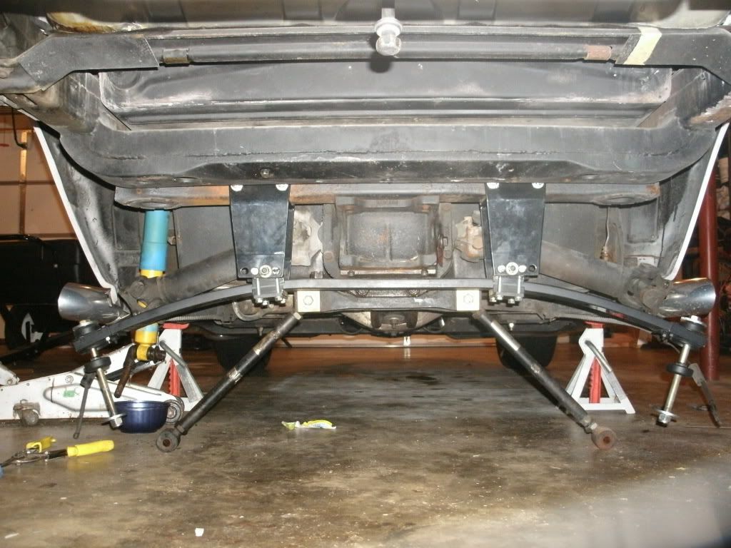
Halloween treat, my driver�s side trailing arm bolt came off as designed.
I had intentions last Monday to take a Dragon Run, but upon bleeding my brakes I discovered my rear calipers leaking which lead to a project I've wanted to take on for some time. Unbolting the drivers side components didn't take too much time, but getting the bolt slid out did.
Questions.
I can't imagine the bolt being that easy to get in during assembly; any tricks?
It's been a while since I've posted; here goes.
[IMG]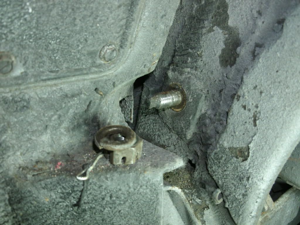 [/IMG]
[IMG]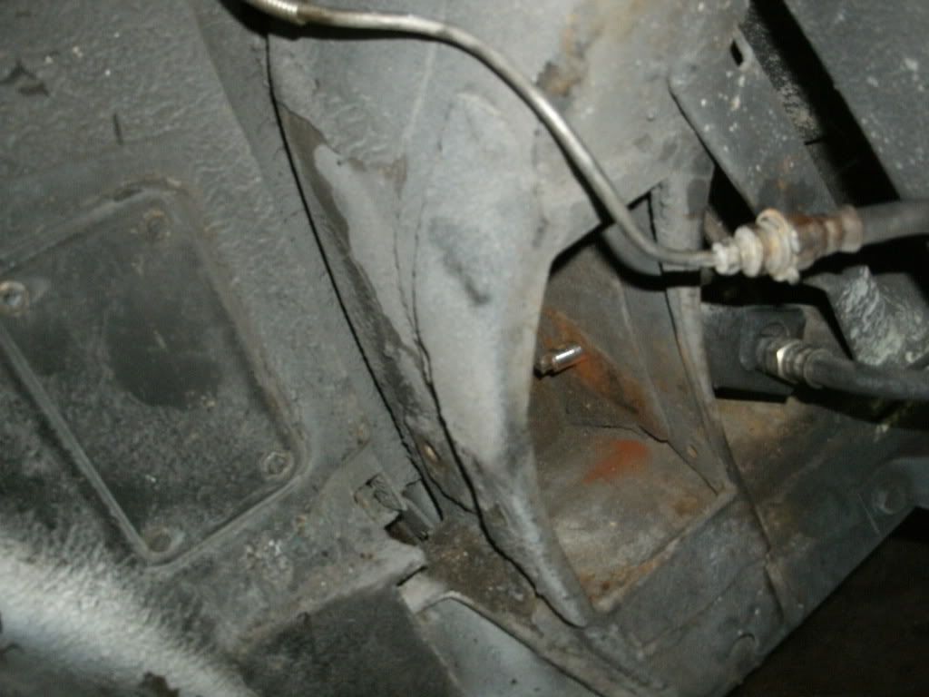 [/IMG]
[IMG]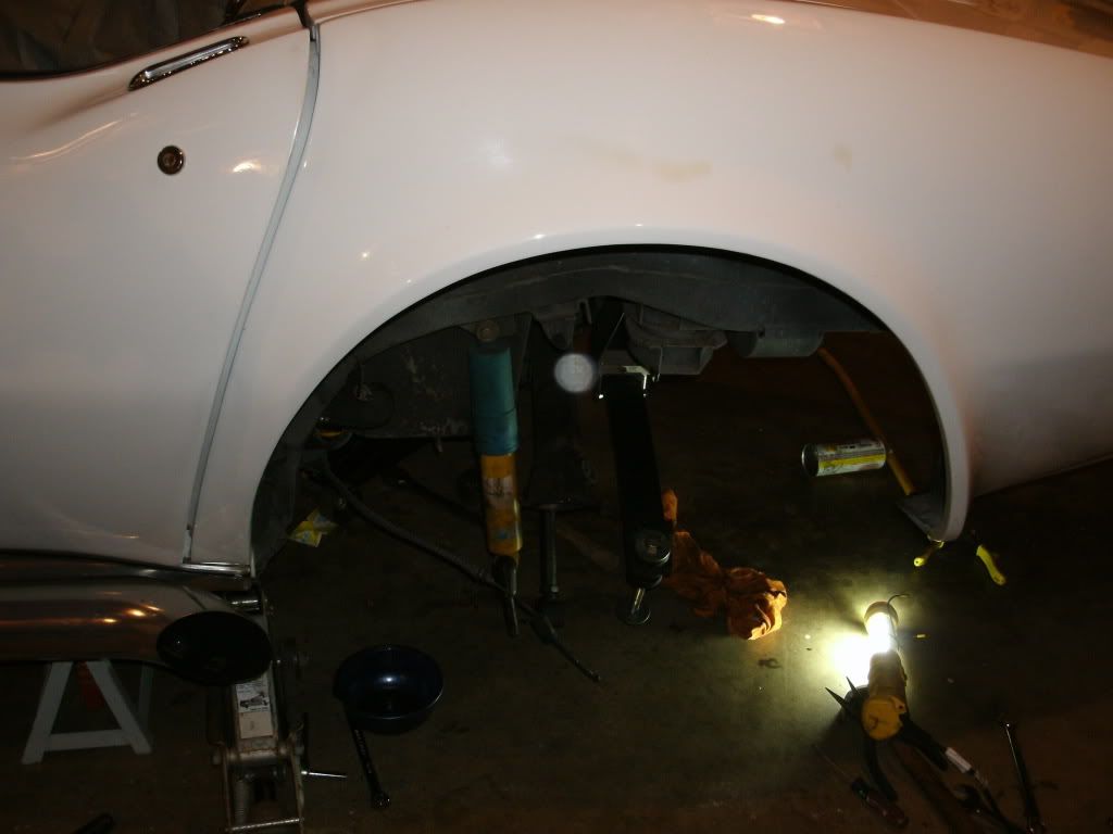 [/IMG]
I had intentions last Monday to take a Dragon Run, but upon bleeding my brakes I discovered my rear calipers leaking which lead to a project I've wanted to take on for some time. Unbolting the drivers side components didn't take too much time, but getting the bolt slid out did.
Questions.
I can't imagine the bolt being that easy to get in during assembly; any tricks?
It's been a while since I've posted; here goes.
[IMG]
[/IMG][IMG]
[/IMG][IMG]
[/IMG]
Last edited by 74 vert; Nov 26, 2009 at 01:21 PM.
Le Mans Master


Joined: Oct 2006
Posts: 7,123
Likes: 433
From: Gladstone MO
C3 of Year Finalist (appearance mods) 2019
When you put the bolt back in, set the T/A in place, then use a coathanger to fish a string thru the frame and T/A. Tie the string thru the cotter key hole and work it back in.
I did it the hard way. I set the T/A in and worked the bolt back in with a long needle nose pliers and lots of real bad words.
I hope the right comes out as easy.
I did it the hard way. I set the T/A in and worked the bolt back in with a long needle nose pliers and lots of real bad words.
I hope the right comes out as easy.
Pro

Joined: Nov 2008
Posts: 542
Likes: 3
From: Bloomfield Hills MI
Yep - needle nose, cursing and beer lube.
Lastly, if you don't have the removable shims, modify your originals so they can be easliy slid out otherwise most alignment shops won't touch the car or you get billed for an extra few hours and one angry alignment guy! I cut mine with an angle grinder then grinding wheel.
Lastly, if you don't have the removable shims, modify your originals so they can be easliy slid out otherwise most alignment shops won't touch the car or you get billed for an extra few hours and one angry alignment guy! I cut mine with an angle grinder then grinding wheel.
Thread Starter
Melting Slicks
Joined: Jan 2003
Posts: 2,165
Likes: 8
From: Where are the Smoky Mountain Cruisers? Not Correctly Restored Stingray
Thanks Guys. I do hope the passenger side comes out as easy. Hopefully, I'll get it out sometime next weekend. I'll post results.
Thread Starter
Melting Slicks
Joined: Jan 2003
Posts: 2,165
Likes: 8
From: Where are the Smoky Mountain Cruisers? Not Correctly Restored Stingray
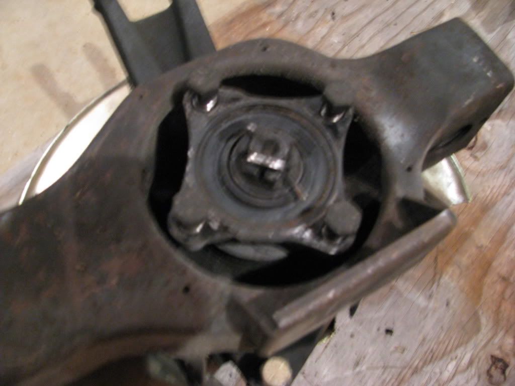
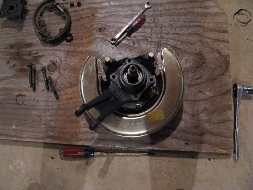
Good news. The passenger TA came out just as easy as the driver's side. I started to take the TA apart, but I can't seem to get the spindle assembly off of the TA. 
Here's an image of where I'm at in the process.
Do I need to remove the cotter-key and nut to separate?

Here's an image of where I'm at in the process.
Do I need to remove the cotter-key and nut to separate?
Last edited by 74 vert; Nov 26, 2009 at 12:05 PM.
Thread Starter
Melting Slicks
Joined: Jan 2003
Posts: 2,165
Likes: 8
From: Where are the Smoky Mountain Cruisers? Not Correctly Restored Stingray
I didn't think I would need special tools to just seperate the spindles from the TA's

Corvette Stories
The Best of Corvette for Corvette Enthusiasts

Every 2027 Corvette Engine Explained
Joe Kucinski
Designer Imagines A Corvette That Looks More Like a Corvette Than the Corvette
Verdad Gallardo
10 Ugly Corvettes That We Still Kinda Love
Joe Kucinski
Top 10 Most Expensive Corvettes Ever Sold on Bring A Trailer
Brett Foote
10 Things Every Corvette Owner Needs (2026 Edition)
Michael S. Palmer
8 Most "Only Corvette Owners Understand" Quirks and Problems
Pouria Savadkouei
10 Reasons the C6 Z06 is Still A Performance Benchmark After 20 Years
Joe Kucinski
How Much Horsepower Every Corvette Engine "LOST" in 1972
Joe Kucinski
Top 10 DOs and DON'Ts for Protecting Your Convertible Top!
Michael S. Palmer
Thread Starter
Melting Slicks
Joined: Jan 2003
Posts: 2,165
Likes: 8
From: Where are the Smoky Mountain Cruisers? Not Correctly Restored Stingray
Removal – Rear Wheel Bearing Assembly
In all: 7 nuts, 6 bolts & 2 clips
Before starting
Note that T-Arm does not have to be removed. This avoids wasted time
and many potential problems.
Also, caliper does not have to be disconnected.
Remove wheel, after very securely supporting frame on jack stands.
Remove rivets. Mark the right rotor if both are removed. If rotor rivets
have not previously been removed, you will need to drill them out. Use 1/4"
drill and drill down 1/2" deep in center of each rivet. Then use a 3/8" drill
bit to remove rivet head. It may be necessary to hammer rivet inward to
break the rotor loose.
Disconnect cable. Gently grasp ball on cable end with wire cutters and pry
ball back out of lever. Tap lever all the way back.
Disconnect shock. Jack up outer end of spring or T-Arm to remove tension
from shock absorber. Remove nut and both washers before prying off lower
end of shock, being careful not to dent shock.
Remove shock mount. Lower jack. Remove cotter pin, clean and oil exposed
threads, and then remove nut, 15/16 socket. Use a tie rod end splitter
or Van Steel’s Shock Mount Remover to break SM loose. SM is usually
rust-seized, so do not hammer on threads or nut. If removal is not possible,
mark camber washer and disconnect other end of strut rod. Ship spindlesupport
assembly with strut rod.
Unbolt axle flange. Suggestions: use 5/8 spark plug socket with breaker
bar and tap socket onto head of bolt to ensure full contact. To keep rotor
from turning, insert a tool into rotor webs near caliper. After unbolting axle
flange, tie it up to the frame.
Remove spindle flange. Remove cotter pin and spindle nut, 1-1/16" socket.Slide flange off spindle.
Unbolt caliper. Suggestions: use 5/8 spark plug socket, 1/2" breaker bar,
and gloves (to protect hands when bolts break loose). Remove flex hose clip
at T-Arm bracket. As caliper is lifted off the rotor, insert 15/16 socket or
similar width object between pads. Guide tubing through bracket and tie
caliper up against frame.
Remove rotor. If both rotors are to be removed, mark the right rotor and
spindle. If parking brakes prevent rotor removal, back off their adjuster by
inserting a screw driver through the rotor’s access hole to contact adjuster’s
star wheel, and push down on handle.
Remove parking brake shoes. Insert thin screw driver through opening
at top of PB shoe and pry out one end of top spring. Pry center of shoe out
from behind spindle. Use pliers to grasp and push in on retaining clip while
rotating anchor pin with needle-nose pliers.
Separate assembly from T-Arm. Clean and oil threads, then remove
(4) nuts with 9/16 box wrench. It may be necessary to tap the support
with a hammer or wedge a screw driver between it and T-Arm.
Do not attempt to press or hammer spindle out of support. The inner
bearing race becomes tightly bonded to it and conventional means of removal
usually ruin the spindle.
What's the spindle flange? I wish I had a exploded view of the TA assembly with labels
Race Director


Joined: Jul 2001
Posts: 15,892
Likes: 42
You really should think about rebuilding them and not just swapping over. Here's a pictorial
http://blog.scottsvettetalk.com/2007...m-rebuild.aspx
Last edited by Mike Ward; Nov 26, 2009 at 01:16 PM.

Drifting

Joined: Oct 2007
Posts: 1,317
Likes: 22
From: Marina CA
I drilled a 1/8" hole out on the tapered tip and used some monofilament line to pull the bolts through. If you use the cotter pin holes depending on the size of the line it will want to bind up on the bushing wall because of limited clearance between the bolt and the bushing wall.
You probably have the slotted shims as the cotter pin that retains them is visible. Buy a good set of stainless steel shims and throw the old rusty original steel ones in the scrap metal pile.
You probably have the slotted shims as the cotter pin that retains them is visible. Buy a good set of stainless steel shims and throw the old rusty original steel ones in the scrap metal pile.
Melting Slicks

Joined: May 2006
Posts: 2,590
Likes: 403
From: Nashville TN
St. Jude Donor '09
I'd love to do the Dragon sometime. Some of the local Mt. Juliet vette guys go in February when the bikes aren't out. I've almost got my car to the point where I could make that run . . . well, except for not having a heater.
I did my brakes, TAs and suspension last year. I got lucky I guess, everything came out and went back in pretty easy. Good luck!!!!
I did my brakes, TAs and suspension last year. I got lucky I guess, everything came out and went back in pretty easy. Good luck!!!!
Thread Starter
Melting Slicks
Joined: Jan 2003
Posts: 2,165
Likes: 8
From: Where are the Smoky Mountain Cruisers? Not Correctly Restored Stingray
I'd love to do the Dragon sometime. Some of the local Mt. Juliet vette guys go in February when the bikes aren't out. I've almost got my car to the point where I could make that run . . . well, except for not having a heater.
I did my brakes, TAs and suspension last year. I got lucky I guess, everything came out and went back in pretty easy. Good luck!!!!
I did my brakes, TAs and suspension last year. I got lucky I guess, everything came out and went back in pretty easy. Good luck!!!!
I also don't have a heater.
 or a good top.
Thread Starter
Melting Slicks
Joined: Jan 2003
Posts: 2,165
Likes: 8
From: Where are the Smoky Mountain Cruisers? Not Correctly Restored Stingray
The 1 1/16 nut came off easy and I was able to bang the 4 bolts out after using some PB Blaster to pry the spindle assemby from the stock TA.
New question, should I use the original 4 bolts that came off the stock TA with the new off-set trailing arm?
New question, should I use the original 4 bolts that came off the stock TA with the new off-set trailing arm?
Last edited by 74 vert; Nov 27, 2009 at 06:09 PM.


Thread Starter
Melting Slicks
Joined: Jan 2003
Posts: 2,165
Likes: 8
From: Where are the Smoky Mountain Cruisers? Not Correctly Restored Stingray
Back from 2009. 2011, I have new wilwood brakes and rotors, thanks Nick; strut rods with heim joints, stainless steel TA shims. Now is the time to get crackin. Need to get to the mountains.
Pics on the way. Questions to follow.
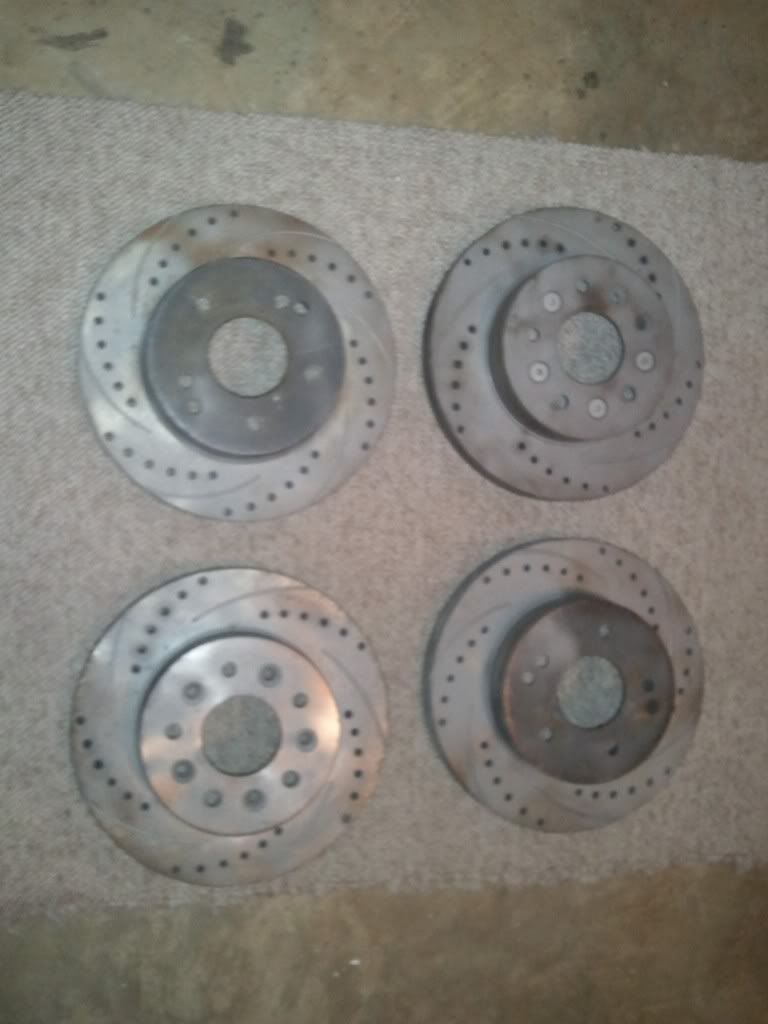
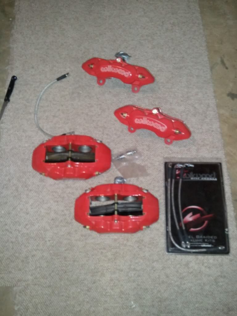
To bad these will be hidden behind the rally wheels.
Pics on the way. Questions to follow.
To bad these will be hidden behind the rally wheels.
Last edited by 74 vert; Feb 19, 2011 at 10:58 PM.