


"Budget" 540 Build
Thread Starter
Le Mans Master


Joined: Dec 2006
Posts: 5,557
Likes: 9
From: Oquirrh Mountains
St. Jude Donor '09
This started about five years ago as a 496 build. I began acquiring parts here and there as various deals presented themselves. TKO 600 - $1500. 454 - $200. Eddy Perf RPM heads - $1500, etc. And then it happened. I work across N. America and while in Michigan, came across a Mercruiser 502 last fall that the guy dropped a supercharger on and proceeded to nuke the engine. #1 and #2 rods broke about 1" above the crankpin and took a few small chunks out of the bottom of #1 & #2 bores. Here's a shot of the damage:

I picked this mess up for five bens and after a couple more, got it shipped back home. I was able to sell the heads for $400, the crank for $200, the rods for $250 (I happened to have two others to match them). Which left me with a 502 block and about $150 in the black. Because of some scarring in the bores, I ended up sleeving both 1 & 2 since the recommended overbore on these Gen VI blocks is only +0.030" and they wouldn't clean up at that. The block was then checked for any other problems and then machined Here's a shot of the one of the sleeves installed before I had it decked:

Anyway, I originally meant to build the 502 instead of the 496; for a few days anyway. The allure of building a bigger big block, however, was already working away and after Snowman's build via Jim (427Hotrod) last fall. I ended up selling most of the 496 parts I had accumulated.
I Picked up a Gen 6 Eagle 10 under 4.25" 4340 crank for $500. I kept the 6.385" bushed scat rods and added a set of SRP pistons & rings:

Here's a shot of the crank in the block:

To be continued. . .
I picked this mess up for five bens and after a couple more, got it shipped back home. I was able to sell the heads for $400, the crank for $200, the rods for $250 (I happened to have two others to match them). Which left me with a 502 block and about $150 in the black. Because of some scarring in the bores, I ended up sleeving both 1 & 2 since the recommended overbore on these Gen VI blocks is only +0.030" and they wouldn't clean up at that. The block was then checked for any other problems and then machined Here's a shot of the one of the sleeves installed before I had it decked:
Anyway, I originally meant to build the 502 instead of the 496; for a few days anyway. The allure of building a bigger big block, however, was already working away and after Snowman's build via Jim (427Hotrod) last fall. I ended up selling most of the 496 parts I had accumulated.
I Picked up a Gen 6 Eagle 10 under 4.25" 4340 crank for $500. I kept the 6.385" bushed scat rods and added a set of SRP pistons & rings:
Here's a shot of the crank in the block:
To be continued. . .
Last edited by Ben Lurkin; Aug 31, 2010 at 12:16 AM.
Race Director


Joined: Jan 2000
Posts: 13,017
Likes: 2,261
From: Corsicana, Tx
2020 C2 of the Year - Modified Winner
2020 Corvette of the Year (performance mods)
C2 of Year Winner (performance mods) 2019
2017 C2 of Year Finalist
This is gonna be fun!! I know where we're heading!!
JIM
JIM

Le Mans Master


Joined: Jun 2004
Posts: 6,231
Likes: 65
From: Seattle WA
St. Jude Donor '14
That's awesome! Always great to see a smart build from good buys.
Any concerns about the damage on the bottom of the bore? Did you consider adding just an inch or so of block filler?
Any concerns about the damage on the bottom of the bore? Did you consider adding just an inch or so of block filler?
Le Mans Master
Joined: May 2006
Posts: 9,993
Likes: 1,136
From: League City Tx
So...you can get 540" out of a stock but bored 502 block with a 4.25" crank? I didn't realize the bore on a 502 was THAT much bigger....
I always see 540s built out of Dart, Merlin blocks...I didn't know you could get that out of a 502....
I just happen to know where there is a good running 502 available....hmmmm
I always see 540s built out of Dart, Merlin blocks...I didn't know you could get that out of a 502....
I just happen to know where there is a good running 502 available....hmmmm
Thread Starter
Le Mans Master
Joined: Dec 2006
Posts: 5,557
Likes: 9
From: Oquirrh Mountains
St. Jude Donor '09
So...you can get 540" out of a stock but bored 502 block with a 4.25" crank? I didn't realize the bore on a 502 was THAT much bigger....
I always see 540s built out of Dart, Merlin blocks...I didn't know you could get that out of a 502....
I just happen to know where there is a good running 502 available....hmmmm
I always see 540s built out of Dart, Merlin blocks...I didn't know you could get that out of a 502....
I just happen to know where there is a good running 502 available....hmmmm
4.47" bore + 4" stroke = 502
4.50" bore + 4.25" stroke = 540

GM says the block will take a 4.6" stroke. With the standard 9.8" deck height you'll start getting excessive rod angularities IMHO. Plus, pistons are a custom order for a reasonable street comp ratio.
Last edited by Ben Lurkin; Aug 31, 2010 at 07:05 PM.
Thread Starter
Le Mans Master
Joined: Dec 2006
Posts: 5,557
Likes: 9
From: Oquirrh Mountains
St. Jude Donor '09

Pro

Joined: Apr 2006
Posts: 625
Likes: 49
From: Southern California
Nice, but one thing to be aware of. The aftermarket blocks like Dart and others, have lifter valley bosses that accept head studs that replace what would otherwise be missing head bolts on 4 of the cylinders. You don't have that option with your block, so you might want to keep the compression ratio as well as the final HP number on the modest side. That way you won't have too much risk of blowing the head gasket in those areas. Some builders call those missing head bolt areas, blow holes. But keeping that in mind, you should be able to stay out of trouble and have a real nice motor. Enjoy
Corvette Stories
The Best of Corvette for Corvette Enthusiasts

Top 10 Most Expensive Corvettes Ever Sold on Bring A Trailer
Brett Foote
10 Things Every Corvette Owner Needs (2026 Edition)
Michael S. Palmer
8 Most "Only Corvette Owners Understand" Quirks and Problems
Pouria Savadkouei
10 Reasons the C6 Z06 is Still A Performance Benchmark After 20 Years
Joe Kucinski
How Much Horsepower Every Corvette Engine "LOST" in 1972
Joe Kucinski
Top 10 DOs and DON'Ts for Protecting Your Convertible Top!
Michael S. Palmer
Top 10 Most Explosive Corvettes Ever Made: Power-to-Weight Ratio Ranked!
Joe Kucinski
150 hp to 1,250 hp: Every Corvette Generation Compared by the Specs That Matter
Joe Kucinski
8 Coolest Corvette Pace Cars (and Replicas) of All Time
Verdad Gallardo
Burning Brakes

Joined: May 2003
Posts: 1,035
Likes: 9
From: Hernando Beach Fl
Hanging out with Jim (427 Hotrod) can probably be fun, but also likely expensive. He is a wealth of knowledge and good for morale.
Keep up the post, sounds like it will be a interesting build to follow.
R.J.
Keep up the post, sounds like it will be a interesting build to follow.
R.J.


Drifting

Joined: Aug 2004
Posts: 1,883
Likes: 124
From: Lubbock TX
Sleeves shouldn't be an issue, there's very little force applied to the lower part of the bore since there is very little angle between the rod pin and wrist pin. I have a Big M getting a pair of sleeves for the same reason and plan to whoop on it like I stole it including some pretty hefty doses of spray.
Le Mans Master
Joined: Jun 2004
Posts: 6,231
Likes: 65
From: Seattle WA
St. Jude Donor '14
You've got a good shop - I'd be interested in hearing their thoughts

Thread Starter
Le Mans Master
Joined: Dec 2006
Posts: 5,557
Likes: 9
From: Oquirrh Mountains
St. Jude Donor '09
I mentioned in the original post I picked up some Eddy RPM's. Since their flow numbers are somewhat weak, particularly for this size of engine; I flipped them on ebay along with a number of my other 496 parts I wouldn't use. I planned on getting a pair of AFR 325's with the CNC chamber option; but came across these instead for $1450/pair last winter. Edelbrock discontinued them and dumped their remaining inventory in their E-store. They are a 325 cc CNC head (well, mostly) with 112 cc combustion chambers. This yields a 10.8:1 static comp ratio, but the cam is 254* duration so it'll still run on premium.

These are a CNC ported version of the Perf RPM heads, and while they don't quite keep up with the AFR heads after 0.400" lift, they do have some really impressive low lift flow #'s. The exhaust port is particularly improved over the RPM head, and it's still in the stock location. Here's how they stack up to the AFR's:

The AFR #'s were from a CC (?) article and Edelbrock's are from their website. Here's some shots of the CNC work:


The combustion chambers and exhausts are fully CNC'd, but the intakes are only bowl blended and port matched. Edelbrock didn't exactly mention that! Quite frankly, I was disappointed in the CNC work on the intake side. there were fairly substantial ridges left where the CNC work met the original casting of the runners. A few hours of work with the die grinder fixed 'em up nicely though. You can see this in the intake port shots.
The springs are pacaloy with 145 # on the seat and 465 # at 0.670 lift on my cam. The retainers are 10* Del West titanium to help lighten the valvetrain up a bit.
These are a CNC ported version of the Perf RPM heads, and while they don't quite keep up with the AFR heads after 0.400" lift, they do have some really impressive low lift flow #'s. The exhaust port is particularly improved over the RPM head, and it's still in the stock location. Here's how they stack up to the AFR's:
The AFR #'s were from a CC (?) article and Edelbrock's are from their website. Here's some shots of the CNC work:
The combustion chambers and exhausts are fully CNC'd, but the intakes are only bowl blended and port matched. Edelbrock didn't exactly mention that! Quite frankly, I was disappointed in the CNC work on the intake side. there were fairly substantial ridges left where the CNC work met the original casting of the runners. A few hours of work with the die grinder fixed 'em up nicely though. You can see this in the intake port shots.
The springs are pacaloy with 145 # on the seat and 465 # at 0.670 lift on my cam. The retainers are 10* Del West titanium to help lighten the valvetrain up a bit.
Last edited by Ben Lurkin; Aug 31, 2010 at 11:28 PM.
Thread Starter
Le Mans Master
Joined: Dec 2006
Posts: 5,557
Likes: 9
From: Oquirrh Mountains
St. Jude Donor '09
With proper installation of the sleeves, which I'm sure is the case, I don't think so. I guess I was just brainstorming a bit that if there was any general weakening of the area a little Hard Blok wouldn't be a bad thing.
You've got a good shop - I'd be interested in hearing their thoughts
You've got a good shop - I'd be interested in hearing their thoughts
Last edited by Ben Lurkin; Aug 31, 2010 at 11:24 PM.
Drifting
Joined: Aug 2004
Posts: 1,883
Likes: 124
From: Lubbock TX
The newer 502's can go 4.600, but I don't know when the break happened, they're very similar to the Gen 5 Sportsman blocks except for splayed mains and coolant holes in the deck. Sonic checking is the only way to know for sure, but you're fine at 4.500 with any 502 block.
Thread Starter
Le Mans Master
Joined: Dec 2006
Posts: 5,557
Likes: 9
From: Oquirrh Mountains
St. Jude Donor '09
Well, I just found out my SD card is junk so this pic will have to do:

I don't have the oil pan on yet, due to a fitment issue, so here's the bottom end:

Main bearings are at 0.030", except #5 which is 0.035". Crank thrust was 0.003, but with a sheet of 600 grit wet/dry and a piece of glass, the thrust is now 0.007"
The rod bearings are 0.020", which is slightly less than what I was shooting for. This is with the one thou oversized bearings too. I didn't really want to grind the crank so this is where they're staying.
Top ring gaps are 0.022",
Second rings are 0.025"
Deck height ended up getting blown a bit. The RH bank is 0.002 in the hole, but the LH bank is 0.008". I was shooting for 0.008" for a total quench of 0.0045 with the gaskets I'm using. I'm not sure if I blew the measurements or the machine shop missed the mark here. I used a machinists straight edge, a dial indicator to bring the pistons to TDC, and a feeler gauge. The LH side was 0.020" in the hole and the RH side was originally 0.028". The LH bank has 0.041" quench and the RH bank has 0.047" it's a little tough to add it back so the heads are now on.
Since the Gen 6 blocks use a different oil pan than the Mk 4 blocks, you are somewhat limited. I went with a Moroso 20411 pan. It has the trapdoor setup like the original corvette big block pan, is kicked out for additional capacity, and is 8" deep. Here's some stock pics of the pan:
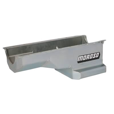
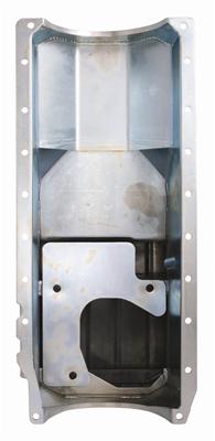
One problem, the pan interferes with the front main cap. I sent it into Moroso and they test fitted it on one of their engines with, of course, no problem. Fitment over the rear pan seal is a bit questionable too. there's about 3/16" more of the seal exposed than at the bottom. You can see the flange isn't quite square to the oil pan rails. But of course, "that's how it's designed" I'll retake the pictures once it shows up again from Moroso.
I don't have the oil pan on yet, due to a fitment issue, so here's the bottom end:
Main bearings are at 0.030", except #5 which is 0.035". Crank thrust was 0.003, but with a sheet of 600 grit wet/dry and a piece of glass, the thrust is now 0.007"
The rod bearings are 0.020", which is slightly less than what I was shooting for. This is with the one thou oversized bearings too. I didn't really want to grind the crank so this is where they're staying.
Top ring gaps are 0.022",
Second rings are 0.025"
Deck height ended up getting blown a bit. The RH bank is 0.002 in the hole, but the LH bank is 0.008". I was shooting for 0.008" for a total quench of 0.0045 with the gaskets I'm using. I'm not sure if I blew the measurements or the machine shop missed the mark here. I used a machinists straight edge, a dial indicator to bring the pistons to TDC, and a feeler gauge. The LH side was 0.020" in the hole and the RH side was originally 0.028". The LH bank has 0.041" quench and the RH bank has 0.047" it's a little tough to add it back so the heads are now on.
Since the Gen 6 blocks use a different oil pan than the Mk 4 blocks, you are somewhat limited. I went with a Moroso 20411 pan. It has the trapdoor setup like the original corvette big block pan, is kicked out for additional capacity, and is 8" deep. Here's some stock pics of the pan:
One problem, the pan interferes with the front main cap. I sent it into Moroso and they test fitted it on one of their engines with, of course, no problem. Fitment over the rear pan seal is a bit questionable too. there's about 3/16" more of the seal exposed than at the bottom. You can see the flange isn't quite square to the oil pan rails. But of course, "that's how it's designed"
I'll retake the pictures once it shows up again from Moroso.

Drifting
Joined: Dec 2005
Posts: 1,360
Likes: 3
From: NORTHEAST
Main bearings are at 0.030", except #5 which is 0.035". Crank thrust was 0.003, but with a sheet of 600 grit wet/dry and a piece of glass, the thrust is now 0.007"
The rod bearings are 0.020", which is slightly less than what I was shooting for. This is with the one thou oversized bearings too. I didn't really want to grind the crank so this is where they're staying.
.
Main bearings are at 0.030", except #5 which is 0.035".The rod bearings are 0.020",
30 thousands on the mains I hope that not your bearing clearance and the rods are 20 thousands on the rods.
Or is that a crank thats been turned .020/.030
Thread Starter
Le Mans Master
Joined: Dec 2006
Posts: 5,557
Likes: 9
From: Oquirrh Mountains
St. Jude Donor '09
The crank is ground 10 under on the mains and std on the rods.
The main bearing clearances are three thousandths (0.003") the rods are two thousandths (0.002").
Drifting
Joined: Dec 2005
Posts: 1,360
Likes: 3
From: NORTHEAST
That sounds much better and those clearances look fine for your build.
Thread Starter
Le Mans Master
Joined: Dec 2006
Posts: 5,557
Likes: 9
From: Oquirrh Mountains
St. Jude Donor '09
OK - got the valvetrain installed and set up today. Encountered a few minor issues since I'm using 1.8 ratio Harland Sharp rockers. Before I put the heads on, I did a mock-up. Since the higher ratio moves the fulcrum point inwards, I had to grind a 1/16" radius into all the guideplates for clearance. In addition, I had to clearance one of the exhaust pushrod slots on each head. Edelbrock apparently leaves a small lip on what would be #3 or #6 exhaust. This wouldn't be an issue with the standard 1.7 rockers, but mine just touch the castings. A little tlc with the die grinder and 


Another 'issue' is the intake rocker on #1 and #8 interferes with the indent for the valve cover bolt. Luckily, I'm using stamped steel ones or the rockers on the intake side may have really needed some surgery. In my case, a little shave off of the edge of the rocker was all that was needed.

It almost seems a shame to have to put the valve covers on!

Oh, cam specs for those interested:
Hydraulic Roller Cam
Intake: 254* @ 0.050", 0.666" net lift
Exh: 260* @ 0.050", 0.670" lift
Lobe separation: 114*
Intake CL 112*
Pushrods are "Doug Herbert" aka Manley (they even come in Manley boxes) 0.080" wall pushrods, 7.70" intake and 8.70" on the exhaust side.
Another 'issue' is the intake rocker on #1 and #8 interferes with the indent for the valve cover bolt. Luckily, I'm using stamped steel ones or the rockers on the intake side may have really needed some surgery. In my case, a little shave off of the edge of the rocker was all that was needed.
It almost seems a shame to have to put the valve covers on!
Oh, cam specs for those interested:
Hydraulic Roller Cam
Intake: 254* @ 0.050", 0.666" net lift
Exh: 260* @ 0.050", 0.670" lift
Lobe separation: 114*
Intake CL 112*
Pushrods are "Doug Herbert" aka Manley (they even come in Manley boxes) 0.080" wall pushrods, 7.70" intake and 8.70" on the exhaust side.
Last edited by Ben Lurkin; Sep 7, 2010 at 12:12 AM.