


Installing a Guildstrand 5 link
Thread Starter
Race Director


Joined: Dec 1999
Posts: 19,610
Likes: 778
From: Forked River NJ
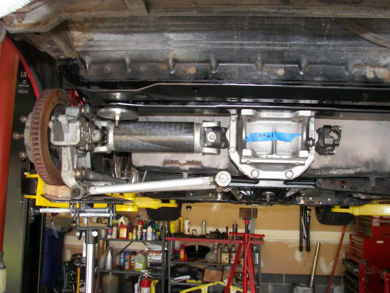
I took on the job of installing a Guildstrand 5 link into a forum members car. I also have put in a Tremec 5 speed in the car while it is here. This is quite a system and I had never seen one before in person. It is not for the faint of heart to install as it takes some frame mods and cutting of the frame pockets where the trailing arms used to be. This car came to me pretty rusty and full of mud. Just surface rust but a lot of mud. When Iremoved the transmission there was mud on the TO bearing and input shaft. There was a ton of small rocks everywhere. The 5 speed went very smoothly and took a few hours to get it all dialed in and installed. ialso made the cross member removeable. I then took everything out of the rear end of the car. Cleaned up what was going to be used again and started the frame work. here are a few pictures. This is just mocked up as to see where more of theframe needs to be removed and how everything was going to fit. This system came off one of his other cars so it is not a new system and some of it came bolted together already. While sawing theframe apart today you should have seen the amount ofdirt that came out. Probably lightened thecar by 20 pounds.


Melting Slicks


Joined: May 2002
Posts: 2,717
Likes: 121
From: Sulphur LA
St. Jude Donor '05-'06,'11,'13-'14,'16,'18,'19,'24, '25
Looks like your moving right along
Does the front section of the Gulstrand system get located with the original TA holes and than welded to the frame?
Neal
Does the front section of the Gulstrand system get located with the original TA holes and than welded to the frame?
Neal
Thread Starter
Race Director
Joined: Dec 1999
Posts: 19,610
Likes: 778
From: Forked River NJ
Yes it does and there lies the problem. The brackets are not quite lining up with the holes. The welded brackets are no problem because they are going to be welded wherever they need to be located. Just a little clearance problem. Nothing that can't be overcome.
Team Owner

Joined: Apr 1999
Posts: 21,953
Likes: 1,445
From: Reno Nevada
2024 C3 of the Year Finalist- Modified
At the shop we were never able to do them with the body on. I wanted to do the adjustable offset swing arm front pivot point bolt assembly and I would have had to cut my cage out and then lift the rear body off my frame.
Le Mans Master

Joined: Apr 2000
Posts: 7,562
Likes: 9
From: B'Ville NY
Cruise-In III Veteran
St. Jude Donor '05
Thread Starter
Race Director
Joined: Dec 1999
Posts: 19,610
Likes: 778
From: Forked River NJ
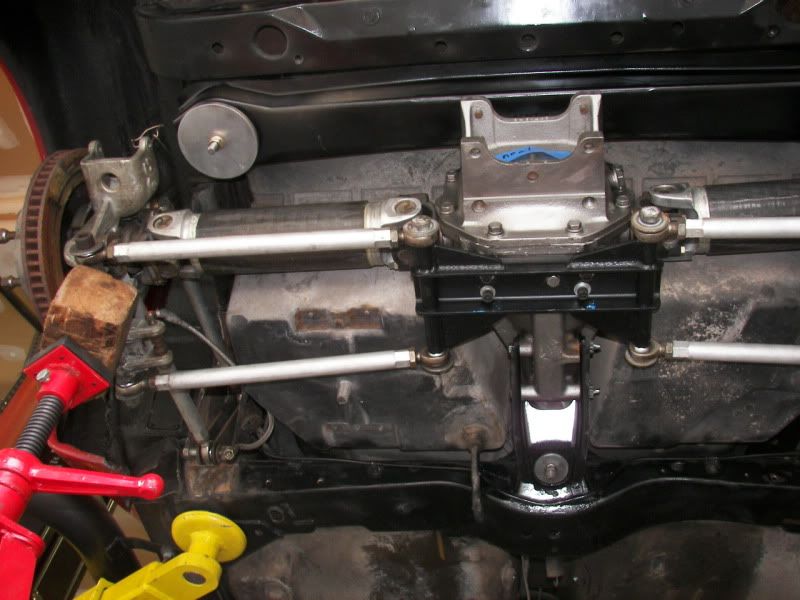
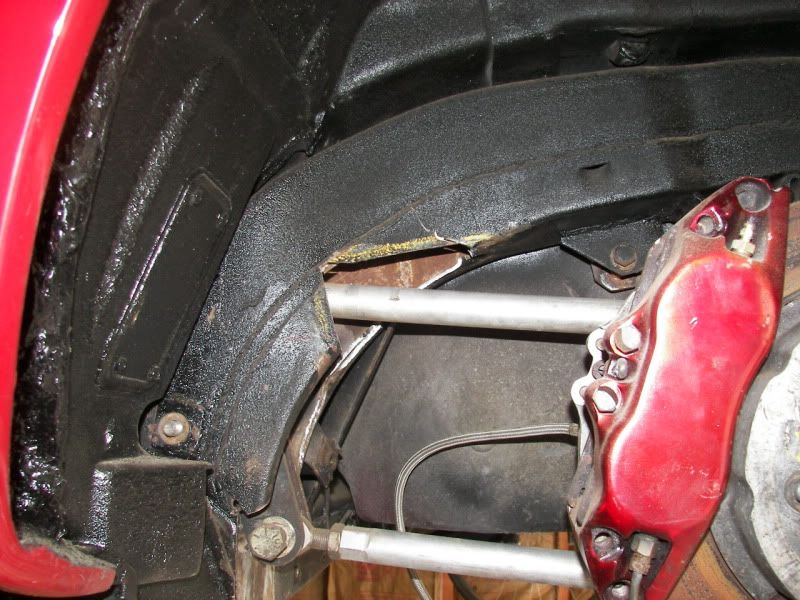
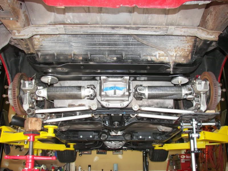
I did some more work today on this. I mocked everything up and got the front brackets to fit. This was not easy. I had to slightly grind the brackets and push in the back of the frame pocket to make it fit. It all fits nicely now. I still have to weld on the tabs for the lower part of the bracket but even with the big carbon fiber halfshafts it all looks good. You can see where I had to clearance the frame for the upper link. It looks ugly and i will clean it up but not a whole lot was removed. Again this is not for the faint of heart because you are hacking away at the frame. As some of you know I work for Lenox Tools and Icut the frame up with some modified blades. iwent throug ha bunch but broke most of them from slamming the frame and bending the crap out of the blades. The frame cuts like butter, somethimes almost to fast so you have to be careful to not cut to much.
Left side
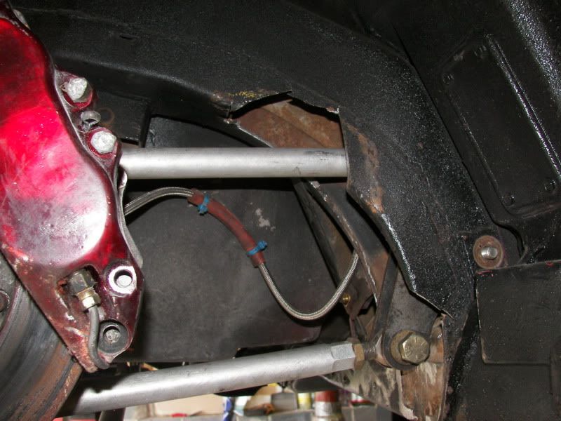
Right side
Rear without the spring in.
Left side
Right side
Rear without the spring in.
Corvette Stories
The Best of Corvette for Corvette Enthusiasts

Every 2027 Corvette Engine Explained
Joe Kucinski
Designer Imagines A Corvette That Looks More Like a Corvette Than the Corvette
Verdad Gallardo
10 Ugly Corvettes That We Still Kinda Love
Joe Kucinski
Top 10 Most Expensive Corvettes Ever Sold on Bring A Trailer
Brett Foote
10 Things Every Corvette Owner Needs (2026 Edition)
Michael S. Palmer
8 Most "Only Corvette Owners Understand" Quirks and Problems
Pouria Savadkouei
10 Reasons the C6 Z06 is Still A Performance Benchmark After 20 Years
Joe Kucinski
How Much Horsepower Every Corvette Engine "LOST" in 1972
Joe Kucinski
Top 10 DOs and DON'Ts for Protecting Your Convertible Top!
Michael S. Palmer
Thread Starter
Race Director
Joined: Dec 1999
Posts: 19,610
Likes: 778
From: Forked River NJ
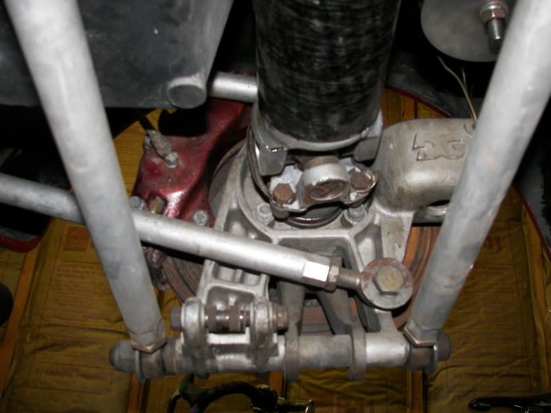
No. The original trailing arm is not used at all. The Guildstrand uses his own bearing carrier. It is a cast piece and has all the mounting points for the rod ends on it. I should take a picture from the inside to show what the carrier looks like.
Here you go.
Here you go.
Last edited by Gordonm; Oct 24, 2010 at 07:29 PM.
Race Director


Joined: Aug 1999
Posts: 18,126
Likes: 174
From: WI
on the original RPF 5-link and even the early ones Guldstrand sold they used a factory trailing arm....the cast "upright" is a newer version.


Thread Starter
Race Director
Joined: Dec 1999
Posts: 19,610
Likes: 778
From: Forked River NJ


Thread Starter
Race Director
Joined: Dec 1999
Posts: 19,610
Likes: 778
From: Forked River NJ
Race Director

Joined: Mar 2006
Posts: 14,112
Likes: 28
From: Florida


Le Mans Master

Joined: Dec 2003
Posts: 5,727
Likes: 39
From: Fremont CA
I have some Greenwood parts, you do NOT have to cut the trailing arm pocket out like this set-up. Front bracket locates off the trailing arm bolt and 2 small angle reinforcments are welded to the underside of the frame below trailing arm opening. I'll post some photos when I get around to mounting it into my 72 LT-1.
Le Mans Master
Joined: Dec 2003
Posts: 5,727
Likes: 39
From: Fremont CA
Here is the assembly drawing for a Greenwood style 5 link. You can see the front bracket locates into the trailing arm pocket.
Anyone who has looked over a GM AIM manual will realize the drarwing is done on the same format, either some guy from GM "moonlighted" for Greenwood or GM spent some time and $$$ comming up with this set-up.
Good thing about it is it is reversible if you want to take it off one day.

Anyone who has looked over a GM AIM manual will realize the drarwing is done on the same format, either some guy from GM "moonlighted" for Greenwood or GM spent some time and $$$ comming up with this set-up.
Good thing about it is it is reversible if you want to take it off one day.
Race Director
Joined: Aug 1999
Posts: 18,126
Likes: 174
From: WI
this is the first page of the install instructions for the original 5-link designed by noted race car designer Bob Riley, designed to be legal for use in SCCA competition. I believe Riley also designed the C-4 rear suspension for GM and Greenwoods stuff... I had one in a 78-82 SCCA car which is why I have the booklet....(the 5-link is long gone). I also had a Greenwood 5-link new in the box, the major difference is the Riley/Guldstrand had two lower links the Greenwood had one on top and one on the bottom.

Last edited by redvetracr; Oct 25, 2010 at 11:07 AM.