


Jim Shea, advice please
Thread Starter
Burning Brakes


Joined: Mar 2006
Posts: 793
Likes: 1
From: Houston Texas
Jim, installing the original non-tilt steering column in my '69 4 speed. With the turn signal housing attached with the 4 screws, the shift tube requires too much force for the interlock cable to overcome without distorting the cable. If I loosen the 4 screws, the force becomes acceptable, due to less compression of the 'shift tube thrust spring'. I have read your papers re this column and browsed some archives. Noted that torque on these screws varied from 50-80 in/lbs. To achieve proper operation of the interlock, the 50 in/lb number is much more acceptable, however my pucker factor is not, considering steering is a critical component and the screws seem too lose. My solution is to loc-tite the screws.
Now my questions. In the chassis service manual, exploded view of the column, there is a 'Spacer' #44, in proximity to the lower bearing. When I disassembled the column this spacer was not present (i feel confident that i was the first to tear this down, post factory). Where does this spacer belong, where do I find one, will it affect my issue?
Last, is the lower bearing not protected from the elements? The 'forward' portion of the race is exposed.
Thank you sir! Dan

Le Mans Master


Joined: Jul 2000
Posts: 6,001
Likes: 115
From: Saginaw Michigan
This is not a very good scan but it is good enough for us to review.

First of all, I believe that there were actually three versions of the 1969 standard steering column. I do not have any information on the early steering column. I have engineering drawings of the interim (7807829) and late (7807890) column assemblies. The above scan is of the interim 7807829 column. Note on this steering column there is a clamp with a nut and bolt on the steering shaft. The clamp is just fastened to the steering shaft and does not even touch any other parts. I can only guess that the expensive clamp was supposed to hold the steering shaft from telescoping in a severe frontal collision. Possibly later car crash testing may have proved that the clamp was not necessary.
Some of the earlier (1967-68) Corvette steering columns had the above style clamp and a plastic spacer and spring that pressed against the lower bearing.
There is no clamp on the late steering column 7807890 nor on any Corvette standard steering columns after 1969.
Concerning the lower end of these two columns the parts are identical. The washer 7807427, shift tube return spring 7804446, lower bearing adapter 7805822, bearing 7805700, bearing adapter retainer 7804440, and the clip 7804439 are all the same parts. In fact all of these lower end parts are the same through 1979.
The 7805700 lower bearing was used on nearly all GM steering columns over many years. It was used on millions and millions of GM cars. I think that there was some type of seal built into the end of the bearing exposed to the underhood environment.
I do not have a 1969 Chevrolet Chassis Service Manual. I have several manuals but not the 1969 so I am unable to to find the blowup picture with the #44 spacer that you mention. Now from the above scan and drawings, there are no spacers on the interim steering column nor on any of the later columns. So it might be possible that you have an early steering column with different parts than the above drawing. Any chance that you can scan and send me the drawing with the #44 spacer? A digital picture of the lower end of your steering column would also be helpful.
Jim
Thread Starter
Burning Brakes
Joined: Mar 2006
Posts: 793
Likes: 1
From: Houston Texas
Yes sir, I will get you a scan and photo of the lower column. As far as the date of the car it was built October 1969, there is no clamp as pictured. All other parts are there, though parts 822 and 440 seem to me to be one item, the plastic bearing retainer that the lower bearing snaps into. It will be tomorrow morning before I can respond with the scan and photo.
Thanks Jim, I look forward to learning!
Dan
Thanks Jim, I look forward to learning!
Dan
Thread Starter
Burning Brakes
Joined: Mar 2006
Posts: 793
Likes: 1
From: Houston Texas
Ok, you got me lying, I couldn't wait till tomorrow. The car is going thru a clean-up as it was too original for me to bear the thought of "restoring" it. The column as pictured has the turn signal housing off, thus the spring is not compressed.


Le Mans Master
Joined: Jul 2000
Posts: 6,001
Likes: 115
From: Saginaw Michigan
So your 1969 was built in October 1969 so that makes your steering column a late design. Verified by no clamp on your steering shaft. There is no spacer on the steering column assembly drawing. The blowup in the Service Manual does call out a spacer.
However, the blowup drawing is pretty generic. Note that the steering column jacket in the drawing does not have a welded capsule bracket. All C3 Corvettes (1969 through 1982) had welded brackets.
I just found a Camaro steering column drawing with a plastic spacer. Not sure what it does but your generic blowup drawing shows it.

Jim
However, the blowup drawing is pretty generic. Note that the steering column jacket in the drawing does not have a welded capsule bracket. All C3 Corvettes (1969 through 1982) had welded brackets.
I just found a Camaro steering column drawing with a plastic spacer. Not sure what it does but your generic blowup drawing shows it.
Jim
Thread Starter
Burning Brakes
Joined: Mar 2006
Posts: 793
Likes: 1
From: Houston Texas
Welded capsule bracket? Is that the piece that the bearing retainer fits into?
OK, so no 'spacer'. Am I doing something wrong with the turn signal housing that causes the lower spring to bind and prevent the shift tube from moving with ease? Or should those screws be relatively 'lose' to what one would otherwise expect (50 in/lbs)??
OK, so no 'spacer'. Am I doing something wrong with the turn signal housing that causes the lower spring to bind and prevent the shift tube from moving with ease? Or should those screws be relatively 'lose' to what one would otherwise expect (50 in/lbs)??
Le Mans Master
Joined: Jul 2000
Posts: 6,001
Likes: 115
From: Saginaw Michigan
I have specifications of 60 inch-lbs and 50 inch-lbs for the housing to jacket screws #10 in your blowup. The spring on the lower end of the column should be pushing the shift tube up into the plastic thrust cup #21 in your blowup. So the torque on the housing screws should not be affecting the rotation of the shift tube.
This is what we called the capsule bracket.
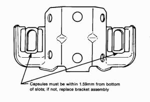
The aluminum capsules breakaway from the bracket as the column collapses in a severe frontal collision. Most GM columns have a capsule bracket that is bolted to the column jacket. The C3 bracket is welded to the jacket. That is why I call your blowup picture "generic". The Corvette capsule bracket is not serviceable it is permanently welded to the jacket.
Jim
This is what we called the capsule bracket.
The aluminum capsules breakaway from the bracket as the column collapses in a severe frontal collision. Most GM columns have a capsule bracket that is bolted to the column jacket. The C3 bracket is welded to the jacket. That is why I call your blowup picture "generic". The Corvette capsule bracket is not serviceable it is permanently welded to the jacket.
Jim
Thread Starter
Burning Brakes
Joined: Mar 2006
Posts: 793
Likes: 1
From: Houston Texas
Dan
EDIT: On further inspection. Service manual implies that the shift lever housing should come off with the turn signal housing removed. It will not come off the shift tube. It appears to me that the shift tube is not inserted far enough into the shift lever housing, resulting in the shift tube extending too far down the column which then causes the spring to bind after tightening the screws. How is this possible/what is the problem? How does the shift tube attach to the housing?
Last edited by jetjockey; Sep 23, 2011 at 10:23 AM.
Corvette Stories
The Best of Corvette for Corvette Enthusiasts

5 Best & 5 Worst Corvette Daily Drivers
Joe Kucinski
The Headlights of Every Corvette Generation Explained
Joe Kucinski
5 Best & 5 Most Overrated Corvette Track Packages of All Time!
Joe Kucinski
Every 2027 Corvette Engine Explained
Joe Kucinski
Designer Imagines A Corvette That Looks More Like a Corvette Than the Corvette
Verdad Gallardo
10 Ugly Corvettes That We Still Kinda Love
Joe Kucinski
Top 10 Most Expensive Corvettes Ever Sold on Bring A Trailer
Brett Foote
10 Things Every Corvette Owner Needs (2026 Edition)
Michael S. Palmer
8 Most "Only Corvette Owners Understand" Quirks and Problems
Pouria Savadkouei
Le Mans Master
Joined: Jul 2000
Posts: 6,001
Likes: 115
From: Saginaw Michigan
The shift tube should be a slip fit into the shift bowl #28. After all these years the two may be corroded together. Drip some penetrating oil on the connection.
BE VERY CAREFULL: The shift tube is made up of two pieces of thin tubing that are held together with injected plastic. (That connection is half way up inside the steering column itself.) If you compress the shift tube and shear the plastic you are going to be in big trouble. I know of no place that sells shift tubes. So handle with care as you work on the shift tube to shift bowl connection. The two should just slide together with very little slop.
Don't forget that after you remove the lower bearing and adapter, the lever arm on the shift tube must be aligned with the "window" on the steering column jacket in order for the shift tube to slide out of the jacket.
Just for additional information. The standard (non-adjustable) column has a slip fit shift tube to shift bowl connection. That is why there is a spring pushing the shift tube back up into the steering column jacket.
The T&T steering column has an interference fit between the shift tube and the shift bowl. So there is no lower spring. This design requires extreme care in disassembly of the two parts.
Jim
Last edited by Jim Shea; Sep 23, 2011 at 10:50 AM.
Thread Starter
Burning Brakes
Joined: Mar 2006
Posts: 793
Likes: 1
From: Houston Texas
Hmm. Well,if it were yours would you just go with the loc-tite and set the shift tube depth that way? Or would you attempt to set the shift tube further into the shift bowl?
I just love being a guinea pig.
I just love being a guinea pig.
Le Mans Master
Joined: Jul 2000
Posts: 6,001
Likes: 115
From: Saginaw Michigan
I would soak the joint and make the two a slip fit like it was designed. There was a reason that it was designed that way. The spring takes up the tolerance between the two parts by pushing on the shift tube and sliding the shift tube into the shift bowl.
Jim
Jim
Thread Starter
Burning Brakes
Joined: Mar 2006
Posts: 793
Likes: 1
From: Houston Texas
Ok. Before I start soaking it in PB Blaster or some such miracle fluid, would you answer me one last question?
There is exactly 32/64ths of an inch of the shift tube protruding from the collar of the shift bowl. Does that sound correct or not?
The reason I ask is, if it's correct, the problem could lie elsewhere and playing with those nylon shear pins is not high on my list of fun things to do. From the looks of things I have to move the shift tube about 1/8 - 3/16 further into the shift bowl.
EDIT: On further investigation, there is a shoulder on the shift tube, 1 7/16" from the end facing the driver, that mates to a corresponding receptacle of the collar in the shift bowl. Those are flush. So the shift tube depth in the shift bowl is correct. The problem must lie elsewhere. Maybe the lower spring is incorrect? Something else??
EDIT: Problem solved. The lower spring looks like a suspension front coil spring, i.e. one end is pigtailed the other is flattened. The upper nylon spacer is not recessed for the pig-tail, nor is the lower nylon bearing retainer that the spring rides on leading me to believe that spring orientation is irrelevant. The only change I made was to say what if? and I repositioned the spring to have the flattened end up or aft, against the interlock cable lever nylon spacer. No more binding.
Thanks Jim for your input and making me think!!
Last edited by jetjockey; Sep 23, 2011 at 01:26 PM.