


request from Germany : tele steering column
Thread Starter
Intermediate

Joined: May 2011
Posts: 42
Likes: 0
From: South Germany / EUROPE
Hello together,
I'm from Germany, got 3 month ago my 68 conv. with tele steering column (N36) .
The German Corvette Forum couldn�t help me with the following problem.
The steering column is loose 2cm = 0,7874 inch up and down
I understand I can adjust this with the Center Star bolt
Open = free way up and down
Close = should be fixed, but I have still this 0,7874 inch up and down
My technical English vocabulary is very limited, means if you like to give me answer, possible to this with simple words or with pictures
What can I do to eliminate this 2 cm (0,7874 inch) up and down in bolted position
would be great to get some feedback.
Thanks
Ralf

Le Mans Master


Joined: Jul 2000
Posts: 6,001
Likes: 113
From: Saginaw Michigan
Ralph,
Here is a blowup of a typical 1967-68 Corvette telescoping steering column.

My first thought would be that the three screws (#3) that attach the turn signal switch #4, the Cover #6 and the Upper Bearing Housing #5 may have loosened.
If that is the case, you will have to remove the steering wheel and use a puller to remove the steering wheel hub in order to reach those screws.
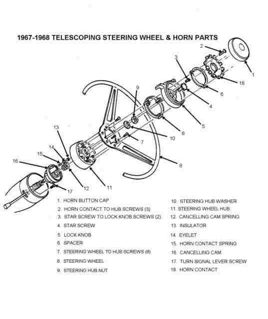
You will note in the above picture that there is a star screw #4 that tightens against a rod inside the steering column. Tightening and loosening the screw either locks the telescope feature or allows it to telescope.
When you use a puller to remove the steering wheel hub, you should protect the threaded end of the steering column steering shaft where the star screw threads are exposed. A metal washer would be sufficient. Otherwise you might damage the female threads in the steering shaft with the puller.
Next and the more severe problem would be that the upper bearing (part of #5 in the first blowup picture) has gone bad. If that is the case you will need to remove the bearing housing from the steering column. You will be able to quickly note if the bearing is missing *****, loose, full of metal particles etc.
You will find that the upper bearing is a press fit into the die cast housing and a thin lip on the housing was spun over to retain the bearing into the housing. You will find that a replacement bearing housing assembly (with bearing) is very rare, and very expensive. You would be best served to try and just replace the bearing into your original housing. Bearings are still available. If you find that this is the real problem, we can address replacement bearings, etc with a further posting.
Good luck,
Jim
Here is a blowup of a typical 1967-68 Corvette telescoping steering column.
My first thought would be that the three screws (#3) that attach the turn signal switch #4, the Cover #6 and the Upper Bearing Housing #5 may have loosened.
If that is the case, you will have to remove the steering wheel and use a puller to remove the steering wheel hub in order to reach those screws.
You will note in the above picture that there is a star screw #4 that tightens against a rod inside the steering column. Tightening and loosening the screw either locks the telescope feature or allows it to telescope.
When you use a puller to remove the steering wheel hub, you should protect the threaded end of the steering column steering shaft where the star screw threads are exposed. A metal washer would be sufficient. Otherwise you might damage the female threads in the steering shaft with the puller.
Next and the more severe problem would be that the upper bearing (part of #5 in the first blowup picture) has gone bad. If that is the case you will need to remove the bearing housing from the steering column. You will be able to quickly note if the bearing is missing *****, loose, full of metal particles etc.
You will find that the upper bearing is a press fit into the die cast housing and a thin lip on the housing was spun over to retain the bearing into the housing. You will find that a replacement bearing housing assembly (with bearing) is very rare, and very expensive. You would be best served to try and just replace the bearing into your original housing. Bearings are still available. If you find that this is the real problem, we can address replacement bearings, etc with a further posting.
Good luck,
Jim
Thread Starter
Intermediate
Joined: May 2011
Posts: 42
Likes: 0
From: South Germany / EUROPE
"Next and the more severe problem would be that the upper bearing (part of #5 in the first blowup picture) has gone bad. If that is the case you will need to remove the bearing housing from the steering column. You will be able to quickly note if the bearing is missing *****, loose, full of metal particles etc.
You will find that the upper bearing is a press fit into the die cast housing and a thin lip on the housing was spun over to retain the bearing into the housing. You will find that a replacement bearing housing assembly (with bearing) is very rare, and very expensive. You would be best served to try and just replace the bearing into your original housing. Bearings are still available. If you find that this is the real problem, we can address replacement bearings, etc with a further posting. "
possible to show me on hand of a real pricture where part 5 is located.
thanks
Ralf
Le Mans Master
Joined: Jul 2000
Posts: 6,001
Likes: 113
From: Saginaw Michigan
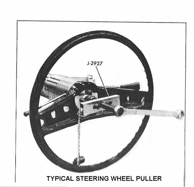
Now you can remove the steering wheel (six screws). Then the steering hub nut. (Be careful that you don't damage the horn contact plunger at 10 o'clock.)
With the hub nut removed you now have to install the puller to remove the hub from the steering shaft. There are two threaded holes in the hub (I believe from your picture they are located at 1 and 7 o'clock either side of the hub nut.) Do not even think about hammering on the hub to get it off instead of using a puller!
Once the hub is removed you will be able to remove the cancelling cam spring #12 and the cancelling cam #16. You will now have the three screws exposed that hold the turn signal switch, bearing housing, and cover. See if the three screws are loose. Hopefully, this is your problem!
Part #5 will be right under the turn signal switch.
Jim
Le Mans Master
Joined: Jul 2000
Posts: 6,001
Likes: 113
From: Saginaw Michigan
Ralf,
For some reason I couldn't reply to your further private message about a steering wheel puller.
The third picture above labeled "Typical Steering Wheel Puller". A puller is a simple bar with a large bolt that threads through the center. Smaller bolts on either side of the larger center bolt screw into two tapped holes in the hub.
Make sure that everything is square. If you **** the puller bar, you can break the smaller bolts that are threaded into the hub.
It may take quite a bit of force but the puller should loosen the hub from the tapered hub and steering shaft.
Jim
Thread Starter
Intermediate
Joined: May 2011
Posts: 42
Likes: 0
From: South Germany / EUROPE
 in that case, before I damage something with my two left hands, my brother (former car mechanic) has to assist me
Thanks a lot for you patient - will take some time but for sure will come back with the result.
Ralf

Corvette Stories
The Best of Corvette for Corvette Enthusiasts

Top 10 Most Expensive Corvettes Ever Sold on Bring A Trailer
Brett Foote
10 Things Every Corvette Owner Needs (2026 Edition)
Michael S. Palmer
8 Most "Only Corvette Owners Understand" Quirks and Problems
Pouria Savadkouei
10 Reasons the C6 Z06 is Still A Performance Benchmark After 20 Years
Joe Kucinski
How Much Horsepower Every Corvette Engine "LOST" in 1972
Joe Kucinski
Top 10 DOs and DON'Ts for Protecting Your Convertible Top!
Michael S. Palmer
Top 10 Most Explosive Corvettes Ever Made: Power-to-Weight Ratio Ranked!
Joe Kucinski
150 hp to 1,250 hp: Every Corvette Generation Compared by the Specs That Matter
Joe Kucinski
8 Coolest Corvette Pace Cars (and Replicas) of All Time
Verdad Gallardo
Le Mans Master
Joined: Jul 2000
Posts: 6,001
Likes: 113
From: Saginaw Michigan
Ralf,
Once the puller breaks the hub from the steering shaft taper, the hub will come right off. The reason you don't want to hammer on the hub to break the taper lock is that you can/will damage the steering shaft bearings with the hammering.
Jim
Once the puller breaks the hub from the steering shaft taper, the hub will come right off. The reason you don't want to hammer on the hub to break the taper lock is that you can/will damage the steering shaft bearings with the hammering.
Jim
Last edited by Jim Shea; Dec 14, 2011 at 02:01 PM.
Advanced

Joined: May 2004
Posts: 80
Likes: 0
i also had a loose in/out steering column.
today i carefully pried off the horn cap, undid the three long screws #2 that hold the horn contact plate. removed the plate and the spacer, then was able to access the star screw.
under the lock **** #5 were three thin shims.
took out the two screws #3 that hold lock **** and set the star screw. tightened the star screw clockwise a wee bit and then turned the lock **** completely to the right at the same time aligning the lock **** with the star screw and screwed in the two screws #3 opposite each other.
everything is tight now with the lock **** turned to the right and the loose in/out movement of the column is gone.
thanks to the jim shea docs
'70 vette
Last edited by wolflt1; Dec 14, 2011 at 11:52 AM.
Advanced
Joined: May 2004
Posts: 80
Likes: 0
thanks
wolf


Thread Starter
Intermediate
Joined: May 2011
Posts: 42
Likes: 0
From: South Germany / EUROPE
Hello JIM,
took quiet a long time but we had a very strong winter. In the garage my Vette was waiting at about - 5 to - 15�C, was too cold to do something.
Finally when weather got better I started to follow you instructions - 3 times - but could not find the problem.
NOW FINALLY TODAY checked again with my brother and it was that simple just a loose screw ( steering box)
it's done and my wife is as well happy.
Regards
Ralf
Last edited by GT-Ralle; Apr 15, 2012 at 08:43 AM.
