


Ignition physics for regular guys like me.
Thread Starter
Tech Contributor


Joined: Jun 2004
Posts: 20,914
Likes: 962
From: I tend to be leery of any guy who doesn't own a chainsaw or a handgun.
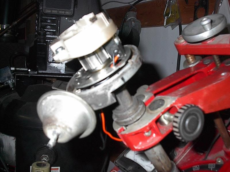
The company I bought the parts from to convert my distributor from points to variable reluctance stopped selling those parts about 10 or 15 years ago. The VR sensor has been very reliable but I always worried what I was going to do if the sensor actually failed. By chance I happened to have some rebuild parts for an old Chrysler distributor that greatly resembled the conversion parts I have in my distributor (I suspect the resemblance is more than just coincidental). While not exactly identical, they were close enough to pique my interest. Here's the reluctor wheel that I'm working on during slow times. I also need to do some machine work on the cam to allow the reluctor to (press) fit on.
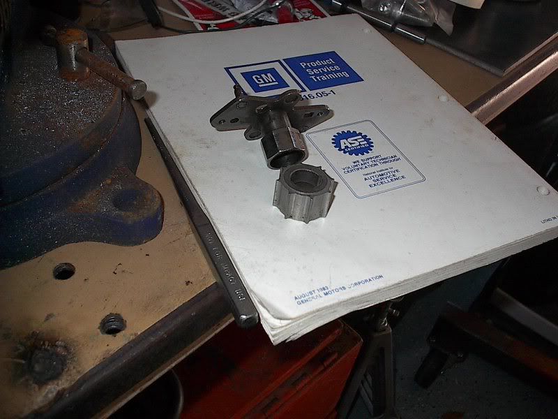
Here's the VR sensor. It looks like it will fit on the breaker plate with minimal headache.
Here's the two parts mocked up. The reluctor is upside down in this picture to allow it to temporarily fit while I'm still figuring out how much I want to machine out.
To repair my current distributor I would obviously only need to swap out the sensor and change the connector. Not a big deal, and thankfully the car would not be out of action very long. The reason I'm spending time fitting an extra reluctor is that it allows me to do some distributor machine work with a spare distributor (using a similar HEI module and some spare coils), and I can debug things there before putting it on the car.
I've also been playing with an HEI sensor at times to see how much work it would be to use in an older distributor, and while it appears that some machined item sizes are similar, it seems there's a vertical height issue with using the HEI sensor. IIRC a little machine work would probably make it fit okay, but that's only an option in the dime a dozen non-tach drive distributors. I don't want to do any irreversible changes to the tach drive distributor housing.
Once I get the car back together I can get back to playing around with these parts again.

Here's the VR sensor. It looks like it will fit on the breaker plate with minimal headache.

Here's the two parts mocked up. The reluctor is upside down in this picture to allow it to temporarily fit while I'm still figuring out how much I want to machine out.

To repair my current distributor I would obviously only need to swap out the sensor and change the connector. Not a big deal, and thankfully the car would not be out of action very long. The reason I'm spending time fitting an extra reluctor is that it allows me to do some distributor machine work with a spare distributor (using a similar HEI module and some spare coils), and I can debug things there before putting it on the car.
I've also been playing with an HEI sensor at times to see how much work it would be to use in an older distributor, and while it appears that some machined item sizes are similar, it seems there's a vertical height issue with using the HEI sensor. IIRC a little machine work would probably make it fit okay, but that's only an option in the dime a dozen non-tach drive distributors. I don't want to do any irreversible changes to the tach drive distributor housing.
Once I get the car back together I can get back to playing around with these parts again.
Last edited by 69427; Feb 10, 2014 at 09:08 PM. Reason: Added content.
Team Owner


Joined: Jul 1999
Posts: 65,492
Likes: 230
From: Orange Park Florida
The company I bought the parts from to convert my distributor from points to variable reluctance stopped selling those parts about 10 or 15 years ago. The VR sensor has been very reliable but I always worried what I was going to do if the sensor actually failed. By chance I happened to have some rebuild parts for an old Chrysler distributor that greatly resembled the conversion parts I have in my distributor (I suspect the resemblance is more than just coincidental). While not exactly identical, they were close enough to pique my interest. Here's the reluctor wheel that I'm working on during slow times. I also need to do some machine work on the cam to allow the reluctor to (press) fit on.
Here's the VR sensor. It looks like it will fit on the breaker plate with minimal headache.
Here's the two parts mocked up. The reluctor is upside down in this picture to allow it to temporarily fit while I'm still figuring out how much I want to machine out.
To repair my current distributor I would obviously only need to swap out the sensor and change the connector. Not a big deal, and thankfully the car would not be out of action very long. The reason I'm spending time fitting an extra reluctor is that it allows me to do some distributor machine work with a spare distributor (using a similar HEI module and some spare coils), and I can debug things there before putting it on the car.
I've also been playing with an HEI sensor at times to see how much work it would be to use in an older distributor, and while it appears that some machined item sizes are similar, it seems there's a vertical height issue with using the HEI sensor. IIRC a little machine work would probably make it fit okay, but that's only an option in the dime a dozen non-tach drive distributors. I don't want to do any irreversible changes to the tach drive distributor housing.
Once I get the car back together I can get back to playing around with these parts again.
more brave than I am.....


Thread Starter
Tech Contributor
Joined: Jun 2004
Posts: 20,914
Likes: 962
From: I tend to be leery of any guy who doesn't own a chainsaw or a handgun.
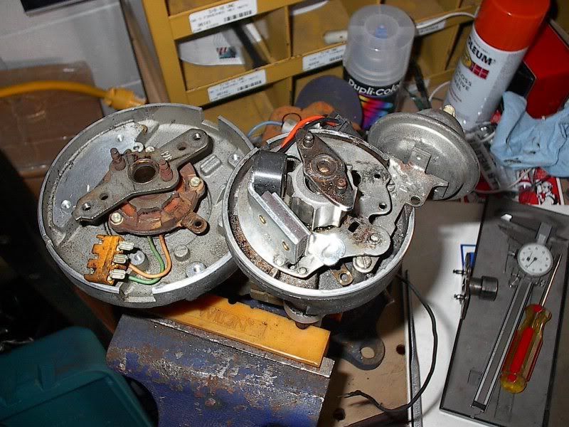
Had a break in the action while waiting for my clutch parts to arrive and worked on the distributor for a bit. Milled down the points cam and pressed on the reluctor wheel.
Next item is to position the VR sensor. Still looking for a couple of the minor parts of the distributor that I've misplaced after the last move, and then I can spin everything up.
(My thanks to mrvette for donating the distributor a while back. I've had a few too many projects going on recently and progress is slower than I like.)
Thread Starter
Tech Contributor
Joined: Jun 2004
Posts: 20,914
Likes: 962
From: I tend to be leery of any guy who doesn't own a chainsaw or a handgun.
Spent a little time today fitting the VR sensor. Got it mounted in there without too much headache. Had a minor interference issue with the rotor screw tips scraping the top of the sensor. I cut off the excess length and things look fine now.
I've finally managed to find most (but not all) of the distributor parts I lost in the last move, so I'm hoping to get this thing completed soon so I can spin it and check the sensor output on my 'scope.

I've finally managed to find most (but not all) of the distributor parts I lost in the last move, so I'm hoping to get this thing completed soon so I can spin it and check the sensor output on my 'scope.
Thread Starter
Tech Contributor
Joined: Jun 2004
Posts: 20,914
Likes: 962
From: I tend to be leery of any guy who doesn't own a chainsaw or a handgun.
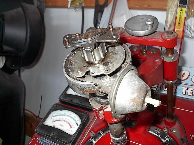
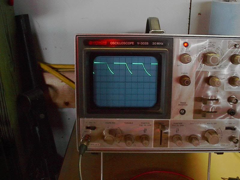
Played around for a bit until the UPS guy dropped off my clutch stuff so I can get back to putting the transmission back in. I found all the parts for the distributor with the exception of the retaining ring that secures the breaker plate. I put everything else together anyway so I could at least briefly check out the operation of the setup. I hooked my scope up to the sensor lines and ran the distributor from zero to 4000 ERPM (2000 distributor RPM). the signal looked very familiar.
In addition to somehow and somewhere finding a replacement snap ring I still need to dig up a piece of brass shim stock to set the air gap between the wheel and the sensor. I've got the gap comparatively wide at the moment, but a smaller gap should yield a larger signal during cranking speeds and a sharper shaped signal at all speeds.
I got an HEI module partially wired up to do some coil testing with, and I'll get back to finishing that up after I get the transmission back in.
Thread Starter
Tech Contributor
Joined: Jun 2004
Posts: 20,914
Likes: 962
From: I tend to be leery of any guy who doesn't own a chainsaw or a handgun.
Took a break from working on the car and wired up an HEI module to the distributor. I still need to rig up a setup to measure the coil primary current, but for now I can make a few voltage measurements. Just running off a battery at the moment, but later I'll hook up a battery charger to more closely simulate the higher voltage of an alternator providing the system voltage.
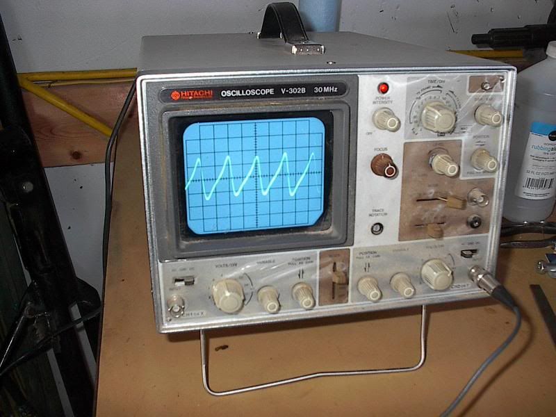
I hooked up a can coil and a ballast resistor to simulate the wiring on a points setup (the HEI module is just a substitute for the points in this simple test). Here's what the voltage/waveshape at the coil C+ terminal looks like with ballast resistor systems.
Note that during the non-dwell times that the voltage at the coil C+ terminal is 12 volts (or 13-14 volts in a vehicle when the alternator is charging). Now, as we know, when dwell starts (points close) the current will start to flow through the ballast resistor and the coil. The current will cause a voltage drop across the ballast resistor. This voltage drop will then subtract from the voltage seen at the coil C+ terminal. In this setup the ballast resistor is 1.2 ohms. When the initial coil current has risen to one amp the (I x R) voltage drop is obviously 1.2 volts. At that point the voltage at the C+ terminal is 12-1.2=10.8 volts. The coil no longer has 12 volts forcing current into the coil so the charge rate slows just a touch. When the current hits two amps the voltage drop across the ballast will be 2.4 volts, yielding 9.6 volts (12-2.4) at the C+ terminal. At three amps the voltage drop is 3.6 volts, yielding 8.4 volts at the C+ terminal. As the current keeps increasing, the voltage across the ballast keeps increasing too. This increasing voltage drop causes the voltage across the coil to decrease, which reduces the voltage "pressure" that pushes additional current into the coil during dwell. You can see in the picture that the initial voltage drop "steepness" changes, and slowly flattens out as the dwell period progresses. This is like the portable air tank analogy I mentioned in a previous post. When you try to fill a small air tank from a hose connected to your large compressor air tank in your garage, you notice how fast the air initially goes into the small tank, but as the small tank starts to fill (and the pressure differential shrinks between your large tank and this small tank) that the small tank fills more slowly. It just takes longer to get the last bit of air into the tank that it took to get the first bit into the tank. If you leave it long enough the air will stop moving into the small tank, and it will be fully "charged". An ignition coil/ballast combo is similar. The initial amount of charging current is "fast", but as the coil current increases (analogous to the air pressure increasing) the charging rate keeps deceasing, and if you leave it long enough it will finally stop increasing any further. In a points setup, that point is reached when the coil has had time to reach the point where the primary current is equal to the battery/system voltage divided by the system resistance (ballast and coil winding resistance). In this setup, the peak current would be 5 amps, as the battery voltage is 12, and the coil winding resistance and ballast resistance are each 1.2 ohms with these parts I had on hand (12/(1.2+1.2)=5).
At casual glance it's obvious that the coil is initially powered by the system voltage, and suffers a reduction in charging efficiency as the dwell period progresses.
Once I get the current measuring setup done some of this will be a bit more obvious.
I hooked up a can coil and a ballast resistor to simulate the wiring on a points setup (the HEI module is just a substitute for the points in this simple test). Here's what the voltage/waveshape at the coil C+ terminal looks like with ballast resistor systems.

Note that during the non-dwell times that the voltage at the coil C+ terminal is 12 volts (or 13-14 volts in a vehicle when the alternator is charging). Now, as we know, when dwell starts (points close) the current will start to flow through the ballast resistor and the coil. The current will cause a voltage drop across the ballast resistor. This voltage drop will then subtract from the voltage seen at the coil C+ terminal. In this setup the ballast resistor is 1.2 ohms. When the initial coil current has risen to one amp the (I x R) voltage drop is obviously 1.2 volts. At that point the voltage at the C+ terminal is 12-1.2=10.8 volts. The coil no longer has 12 volts forcing current into the coil so the charge rate slows just a touch. When the current hits two amps the voltage drop across the ballast will be 2.4 volts, yielding 9.6 volts (12-2.4) at the C+ terminal. At three amps the voltage drop is 3.6 volts, yielding 8.4 volts at the C+ terminal. As the current keeps increasing, the voltage across the ballast keeps increasing too. This increasing voltage drop causes the voltage across the coil to decrease, which reduces the voltage "pressure" that pushes additional current into the coil during dwell. You can see in the picture that the initial voltage drop "steepness" changes, and slowly flattens out as the dwell period progresses. This is like the portable air tank analogy I mentioned in a previous post. When you try to fill a small air tank from a hose connected to your large compressor air tank in your garage, you notice how fast the air initially goes into the small tank, but as the small tank starts to fill (and the pressure differential shrinks between your large tank and this small tank) that the small tank fills more slowly. It just takes longer to get the last bit of air into the tank that it took to get the first bit into the tank. If you leave it long enough the air will stop moving into the small tank, and it will be fully "charged". An ignition coil/ballast combo is similar. The initial amount of charging current is "fast", but as the coil current increases (analogous to the air pressure increasing) the charging rate keeps deceasing, and if you leave it long enough it will finally stop increasing any further. In a points setup, that point is reached when the coil has had time to reach the point where the primary current is equal to the battery/system voltage divided by the system resistance (ballast and coil winding resistance). In this setup, the peak current would be 5 amps, as the battery voltage is 12, and the coil winding resistance and ballast resistance are each 1.2 ohms with these parts I had on hand (12/(1.2+1.2)=5).
At casual glance it's obvious that the coil is initially powered by the system voltage, and suffers a reduction in charging efficiency as the dwell period progresses.
Once I get the current measuring setup done some of this will be a bit more obvious.

Melting Slicks


Joined: Aug 2011
Posts: 3,146
Likes: 263
These measurements are of minimal usefulness. The winding resistance numbers are derived from the gauge (diameters) of the primary and secondary wires, and how stinking long it is in each winding. So, bigger wires result in lower resistance, but shorter wires (ie: less windings) also result in less resistance. The net result is that the resistance measurements don't tell you what size wire is used in your coil, or how many turns are in the coil.
The resistance measurements are good for two things:
1) Determining if you have an open coil (ie: broken internal wire), or a majorly shorted coil.
2) Determining what size ballast resistance you need in conjunction with the primary resistance to keep the primary current from exceeding the manufacturer's recommendation. (Most points systems seem to end up with about three ohms total to keep the primary current in the four amp range. Aftermarket electronic systems vary.)
Notice in 1) above I mentioned majorly shorted coils. It's next to impossible to find a "minorly" shorted coil with the electrical tools available to most car guys (a VOM). A single shorted winding (or even several windings) will most always be such a small percentage of the actual winding count that an ohmmeter won't be able to accurately measure the minute change in the DC resistance. However, a shorted winding can play havoc with the correct operation of the internal magnetic field (where all the energy is supposed to be stored and transferred to the secondary windings), and several things can happen. The shorted winding starts "sucking up" a bunch of the energy that was supposed to be transferred to the secondary (and the plug gap) causing rough engine operation, or the coil gets hot due to the energy dissipating in the coil instead of the plug gap, or the wires fuse/melt open due to the heating and the engine stalls. There's other scenarios too, but you get the idea. Without some reasonably sophisticated equipment to test the coil it's just easier to swap out a questionable coil with a known good one to see if the drivability issue improves.
I am sufficiently enlightened that when running points the rule of thumb for primary current is in the 3-4 amp range and therefore I tailor or match the ballast resistance to achieve this current value.
Whether you are re-inventing something with your triggering conversion is debatable.
I am aware of other people making and selling HEI origin based conversions for point distributors that maintain stock appearance (utilize cannister coils) that have been down this road and addressed concerns in less theoretical but possibly a more practical manner - ie particular coil make and model and specifications most suitable for optimum operation.
Thread Starter
Tech Contributor
Joined: Jun 2004
Posts: 20,914
Likes: 962
From: I tend to be leery of any guy who doesn't own a chainsaw or a handgun.
Yo start off stating that knowing knowing primary resistance is of minimal usefulness That's correct. but then go on to state that coil primary resistance value along with ballast resistance determines primary circuit current which I am well aware of and where I was coming from. You can use that to calculate the maximum current at low RPM. It tells you nothing about what the current will be at mid and higher RPMs, and it tells you nothing about how much energy gets stored into the coil (at any RPM!) for delivery to the plugs. Nothing. If the resistance tells you nothing about the energy storage of the coil, how is it of anything other than minimal usefulness?
I am sufficiently enlightened that when running points the rule of thumb for primary current is in the 3-4 amp range and therefore I tailor or match the ballast resistance to achieve this current value. I'm not a big "rule of thumb" fan. I prefer to know the actual numbers and specs on things. We just look at the world differently, I guess.
Whether you are re-inventing something with your triggering conversion is debatable. I wasn't aware that there were any claims that this setup re-invented anything. Can you refresh my memory where that perception may have come from?
I am aware of other people making and selling HEI origin based conversions for point distributors that maintain stock appearance (utilize cannister coils) that have been down this road and addressed concerns in less theoretical but possibly a more practical manner - ie particular coil make and model and specifications most suitable for optimum operation.
As I've mentioned before, I offer up this information to the group here free of charge. I'm not forcing anyone to understand it, or even try to understand it. That's your choice.
I'm well aware that you're not a big fan of me or my work here. I can live with that. But I don't understand why you spend time on a thread that you appear to have a dislike for?
Corvette Stories
The Best of Corvette for Corvette Enthusiasts

Top 10 Most Expensive Corvettes Ever Sold on Bring A Trailer
Brett Foote
10 Things Every Corvette Owner Needs (2026 Edition)
Michael S. Palmer
8 Most "Only Corvette Owners Understand" Quirks and Problems
Pouria Savadkouei
10 Reasons the C6 Z06 is Still A Performance Benchmark After 20 Years
Joe Kucinski
How Much Horsepower Every Corvette Engine "LOST" in 1972
Joe Kucinski
Top 10 DOs and DON'Ts for Protecting Your Convertible Top!
Michael S. Palmer
Top 10 Most Explosive Corvettes Ever Made: Power-to-Weight Ratio Ranked!
Joe Kucinski
150 hp to 1,250 hp: Every Corvette Generation Compared by the Specs That Matter
Joe Kucinski
8 Coolest Corvette Pace Cars (and Replicas) of All Time
Verdad Gallardo
Melting Slicks
Joined: Aug 2011
Posts: 3,146
Likes: 263
My previous response/post was somehow corrupted - I therefore am removing it.
FYI - I am unable to remove the black print below that is being attributed to me / being shown as a quote from my post - I DID NOT post things shown in the post below.
FYI - I am unable to remove the black print below that is being attributed to me / being shown as a quote from my post - I DID NOT post things shown in the post below.
Last edited by QIK59; Mar 20, 2014 at 12:23 AM.
Thread Starter
Tech Contributor
Joined: Jun 2004
Posts: 20,914
Likes: 962
From: I tend to be leery of any guy who doesn't own a chainsaw or a handgun.
RULE OF THUMB IS GOOD ENGINEERING PRACTISE - hows that ??Optimum is what doesn't fry the points To me optimum is what provides sufficient energy into the coil for reliable and consistent combustion. If I was just worried about the points life I'd just drop the current down to a few milliamps.
I'm noy saying that I'm not a big supporter of yours - what I am saying that what you are doing is nothing new. I've never claimed I'm doing something "new" here. New stuff happens in the lab, I'm working on this stuff in my shop. My point in typing this thread is to pass on some information and experience I gained working in the ignition business, and to correct a few ignition related fairy tales that keep circulating here.
I'm talking private low cost guys that have figured out triggering mechanisms are just triggering mechanisms as you have discovered when comparing HEI and other reluctor outputs. Those private low cost guys figured that out after reading about the parts and components that my former co-workers designed and developed. And I didn't just recently "discover " this stuff. I learned it decades ago when I started in my job. I had the good fortune to work with and be mentored by the guy who designed the HEI electronics.
You apply the trigger to a switching mechansim to actuate a coil.
Ie using MOPAR ignition amps with GM transistorized distributors to get a nore reliable and lower cost effective alternative
You are correct that this is a low cost alternative. It's not in my nature to spend more when I can make it myself for less.
Melting Slicks
Joined: Aug 2011
Posts: 3,146
Likes: 263
Just a side post about the system in my car. It's a combination of stuff that has worked well for me for several years. Some background:
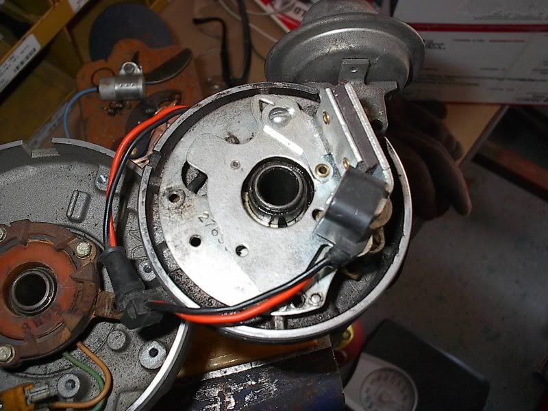
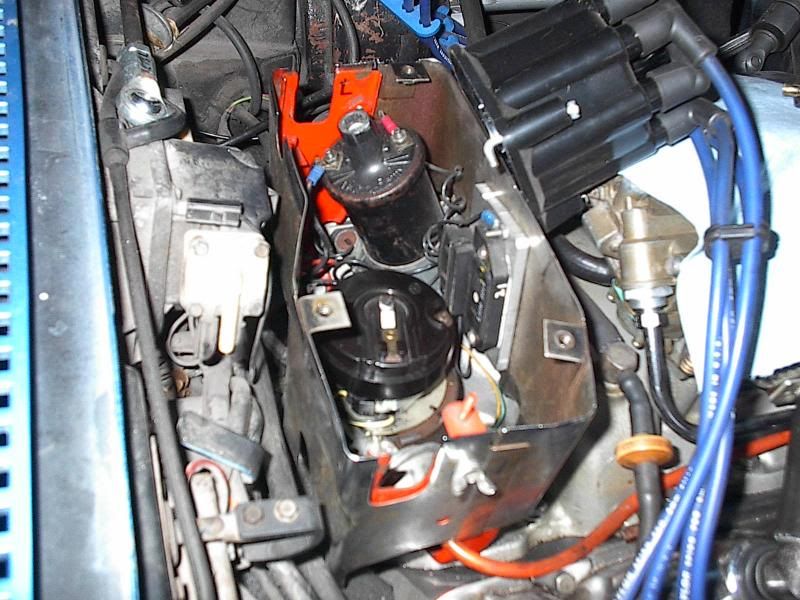
When I first got this car in my teens I noticed that I couldn't get any plug life out of it. It was a box stock 390 horse L-36, with the exception of a Holley spreadbore carb on it that the the PO had installed. I never bothered to ask him why the change. The biggest reason I didn't was probably my unfamiliarity of the details of this car, and I had no idea that the carb had been swapped. Anyway, I was pulling and cleaning the plugs more often that I cared to do. In hindsight I wondered if the carb was jetted too rich, but all things considered it got quite acceptable fuel mileage. Perhaps I had the wrong heat range plugs, but that was a bit too detailed for my teenage brain at the time. Regardless, I saw a presentation in a hot rod magazine about a new electronic ignition conversion setup (this was pre-HEI days) for GM distributors. It was a VR (variable reluctance) sensor and reluctor wheel for the distributor, and a potted up PCB module that was mounted externally. Here's an old picture of the distributor.
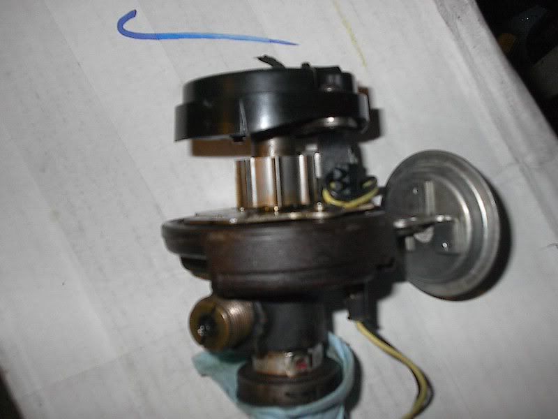
In this fuzzy picture you can see the reluctor wheel and the VR pickup coil. The wheel is (obviously) an eight tooth wheel, which presses on over the points cam, and the pickup coil attaches to the breaker plate in place of the points. (I don't have a picture of the external module, as it took a crap a few years after installation and it's in a landfill somewhere.)
The system worked quite well for several years, but then it started to misfire at higher RPMs under load (personal evidence that electronic ignitions are not always "either working or dead"). I took the system into work one day and hooked everything up on the bench and spun up the RPM. Sure enough the system was breaking up. It looked like the output (switching) transistor was breaking down at higher coil voltages. As the module was all potted up I couldn't debug the circuit board further to repair things, so it went into the trash can. During this testing I noticed that the VR sensor generated an output signal almost identically to that of an HEI distributor (HEI had been in production for several years when I had this problem with the aftermarket system). I thought, what the heck, could I use an inexpensive, readily available HEI module to replace the faulty ignition box? I hooked up a four-terminal HEI module into the system and it worked quite well.
I made up a small harness and installed the HEI module under the distributor shielding. This module looks different than a typical HEI module, but it's the same guts, just in a custom housing for an international customer.
The module is mounted on a modest heat sink. The output transistor stays in saturation mode most of the dwell time so there's minimal wattage/heating of the module. Similarly to a production HEI system I ran a low resistance feed wire to the C+ side of the coil. As I mentioned in an earlier post, coils will operate quite well without a ballast resistor. The coil doesn't care if the system is 6v, 12v, or even 24v. As long as the peak current is controlled then it's happy. I've run the stock coil in this configuration for a couple decades, and several thousand track miles, with complete reliability. As the three engines I've had in this car are big blocks, hyper levels of RPM are not reached, but this system has run well at the rare times when I've run it up to 6200-6500 in the short straights rather than upshift. I don't do this often as it's just unnecessary wear on the engine.
This spring I'm planning on doing some tweaks and tests on the system. With this latest engine I believe I can (should) run a bit more low RPM advance to help out the idle quality and fuel mileage. Also, I've accumulated a few more ignition coils that I'd like to measure their charge time (dwell) requirements and energy levels, just out of curiosity and possible use in the car. I gave away my Sun distributor machine to a friend a few years ago when I moved across the country, but I moved back somewhat close recently and he was kind enough to allow me to have it back. Once I get done with the current project (changing the front suspension roll center and camber curve) I'll wipe the dust off the machine and do some distributor work.
Posted to prevent time out. More to follow.
When I first got this car in my teens I noticed that I couldn't get any plug life out of it. It was a box stock 390 horse L-36, with the exception of a Holley spreadbore carb on it that the the PO had installed. I never bothered to ask him why the change. The biggest reason I didn't was probably my unfamiliarity of the details of this car, and I had no idea that the carb had been swapped. Anyway, I was pulling and cleaning the plugs more often that I cared to do. In hindsight I wondered if the carb was jetted too rich, but all things considered it got quite acceptable fuel mileage. Perhaps I had the wrong heat range plugs, but that was a bit too detailed for my teenage brain at the time. Regardless, I saw a presentation in a hot rod magazine about a new electronic ignition conversion setup (this was pre-HEI days) for GM distributors. It was a VR (variable reluctance) sensor and reluctor wheel for the distributor, and a potted up PCB module that was mounted externally. Here's an old picture of the distributor.

In this fuzzy picture you can see the reluctor wheel and the VR pickup coil. The wheel is (obviously) an eight tooth wheel, which presses on over the points cam, and the pickup coil attaches to the breaker plate in place of the points. (I don't have a picture of the external module, as it took a crap a few years after installation and it's in a landfill somewhere.)
The system worked quite well for several years, but then it started to misfire at higher RPMs under load (personal evidence that electronic ignitions are not always "either working or dead"). I took the system into work one day and hooked everything up on the bench and spun up the RPM. Sure enough the system was breaking up. It looked like the output (switching) transistor was breaking down at higher coil voltages. As the module was all potted up I couldn't debug the circuit board further to repair things, so it went into the trash can. During this testing I noticed that the VR sensor generated an output signal almost identically to that of an HEI distributor (HEI had been in production for several years when I had this problem with the aftermarket system). I thought, what the heck, could I use an inexpensive, readily available HEI module to replace the faulty ignition box? I hooked up a four-terminal HEI module into the system and it worked quite well.
I made up a small harness and installed the HEI module under the distributor shielding. This module looks different than a typical HEI module, but it's the same guts, just in a custom housing for an international customer.

The module is mounted on a modest heat sink. The output transistor stays in saturation mode most of the dwell time so there's minimal wattage/heating of the module. Similarly to a production HEI system I ran a low resistance feed wire to the C+ side of the coil. As I mentioned in an earlier post, coils will operate quite well without a ballast resistor. The coil doesn't care if the system is 6v, 12v, or even 24v. As long as the peak current is controlled then it's happy. I've run the stock coil in this configuration for a couple decades, and several thousand track miles, with complete reliability. As the three engines I've had in this car are big blocks, hyper levels of RPM are not reached, but this system has run well at the rare times when I've run it up to 6200-6500 in the short straights rather than upshift. I don't do this often as it's just unnecessary wear on the engine.
This spring I'm planning on doing some tweaks and tests on the system. With this latest engine I believe I can (should) run a bit more low RPM advance to help out the idle quality and fuel mileage. Also, I've accumulated a few more ignition coils that I'd like to measure their charge time (dwell) requirements and energy levels, just out of curiosity and possible use in the car. I gave away my Sun distributor machine to a friend a few years ago when I moved across the country, but I moved back somewhat close recently and he was kind enough to allow me to have it back. Once I get done with the current project (changing the front suspension roll center and camber curve) I'll wipe the dust off the machine and do some distributor work.
Posted to prevent time out. More to follow.
I have also accumulated some aftermarket canister coils in addition to original OEM GM/Delco coils.
Besides primary resistance values where you able to test your coils for charge time and energy level ?
Coils I have are Mallory 29217 , Accel 8140 , Jacobs (original) 380672, Summit G5215 house coil, 1970's Gratiot Automotive chrome track coil, MSD 8200 plus a few Delco coils.
GM / Delco had a few different part number coils over the years (50's thru the 60's) for Chev V-8 engines - what was the reason for different part numbers - dwell requirements and energy level ??
Are you able to access design parameters for GM / Delco coils ?
Thank you

Last edited by QIK59; May 30, 2014 at 03:11 PM.
Thread Starter
Tech Contributor
Joined: Jun 2004
Posts: 20,914
Likes: 962
From: I tend to be leery of any guy who doesn't own a chainsaw or a handgun.
Okay I have re-read this thread in it's entirety and it now makes sense as to ignition coil characteristics and how the primary circuit operating parameters affect coil operation - Thank You ! and my apologies for getting indignant for not being provided with "useable specifics".
I have also accumulated some aftermarket canister coils in addition to original OEM GM/Delco coils.
Besides primary resistance values where you able to test your coils for charge time and energy level ? Not yet. The last several months I've been busy doing some additional weight reduction projects and suspension geometry changes to the car, and track days are now going on, so fun has taken priority over cerebral activities.
Coils I have are Mallory 29217 , Accel 8140 , Jacobs (original) 380672, Summit G5215 house coil, 1970's Gratiot Automotive chrome track coil, MSD 8200 plus a few Delco coils.
GM / Delco had a few different part number coils over the years (50's thru the 60's) for Chev V-8 engines - what was the reason for different part numbers - dwell requirements and energy level ?? I suspect there were several reasons. Some engines require more spark energy, some engines need quicker energy charge rates due to higher engine speeds, and often when a design or manufacturing change is made to a part the part number is changed to allow the new parts to be differentiated from the older parts, and allow easier tracking for warranty issues.
Are you able to access design parameters for GM / Delco coils ?
Thank you
I appreciate your interest in the topic.
Melting Slicks
Joined: Aug 2011
Posts: 3,146
Likes: 263
I've tried finding actual engineering specs on OEM DR coils but I've never been successful (I haven't given up yet). I've also been trying to find a used current probe/amplifier to measure these coils, but these items are still darn expensive, so I'm working on a less expensive method to measure the primary currents and rise times.
I appreciate your interest in the topic.
I appreciate your interest in the topic.
I have picked up some more chromed performance canister coils - I have been on a mission buying chrome USA made coils as they are NLA - not mfrd (in the USA) any longer.
Got an "original" ? Accel chrome coil from the 70's - it is identical to my Gratiot Performance chrome coil (guess Gratiot was selling them sans Accel label as their house coil).
These coils appear to be epoxy filled (Accel & Gratiot) - both are heavier than any of the other coils and no oil slosh.
Also got some Holley performance chrome coils - these are almost 1" shorter than the other coils I have accumulated.
Racer


Joined: Sep 2008
Posts: 454
Likes: 7
From: SB County CA
69427,
I realize I'm late to the party here, but I wanted to thank you for the effort in your explanations.
If you're interested I think many of us could benefit in a discussion regarding proper timing curves and their factors from a tuning perspective. IE, what timing should I be trying to achieve for various engine speeds and loads...even if only theoretical in nature...
Thanks again!

Burning Brakes

Joined: Jun 1999
Posts: 751
Likes: 0
From: Chandler AZ
St. Jude Contributor
Hi 69427, good stuff for us thank you for taking the time to write it all up.
I was running MSD Superconductor wires on my 496. I after my rebuild I have been dealing with some issues and still am. I found an intermittent contact on my #8 wire. Apparently the MSD plugs don't like to be bent as advertised.
I checked the resistance of the wires as sure enough they are ~ 40 Ohms per foot.
I got a new set of Taylor's spiro Pro. these are an order of magnitude high in series resistance ~ 2K Ohms per foot.
Question, should I be able to even notice the difference even though there is such a large gap in the series resistance between the two sets?
Thread Starter
Tech Contributor
Joined: Jun 2004
Posts: 20,914
Likes: 962
From: I tend to be leery of any guy who doesn't own a chainsaw or a handgun.
69427,
I realize I'm late to the party here, but I wanted to thank you for the effort in your explanations. I appreciate it.
If you're interested I think many of us could benefit in a discussion regarding proper timing curves and their factors from a tuning perspective. IE, what timing should I be trying to achieve for various engine speeds and loads...even if only theoretical in nature...
Thanks again!
Research has shown that the best timing curve (for best thermal efficiency) for most engines is the curve that lights off the mixture so that the peak cylinder combustion pressure occurs when the piston is at 15-20* ATDC. The curve to get this power/efficiency is incredibly easy to derive in a decent research dyno room where pressure sensors are tapped into the cylinder heads, and the pressure waveforms are overlayed on the crankshaft sensor (crank angle position) waveform to see if the combustion pressure peak is happening at the correct time/point. Obviously, the other way to get a decent curve is to use a brake dyno to load the engine, and then tweak the timing until the peak torque at that RPM is obtained.
These methods are great, and very precise, but either impossible or extremely expensive for us mere mortals to use to tune our engines. For most of us our only options are a chassis dyno or the drag strip. These both have limitations due to the fast nature of the RPM sweeps.
I like using a knock sensing circuit when I can, to catch excess (for conditions) spark advance points where a loud exhaust might mask the sound of onset, light detonation.
And, obviously, a lot of "tuning" is done is done by SOTP (hopefully accompanied by a vehicle accelerometer device), or just adapting the timing curve of a similarly built and equipped engine.
There's a whole lot more detail obviously that could be discussed on this topic. IIRC there used to be a timing sticky a few years ago, but I haven't seen it in quite a while. Perhaps you might initiate a new thread and this topic could be revisited and updated.
Thread Starter
Tech Contributor
Joined: Jun 2004
Posts: 20,914
Likes: 962
From: I tend to be leery of any guy who doesn't own a chainsaw or a handgun.
Hi 69427, good stuff for us thank you for taking the time to write it all up.
I was running MSD Superconductor wires on my 496. I after my rebuild I have been dealing with some issues and still am. I found an intermittent contact on my #8 wire. Apparently the MSD plugs don't like to be bent as advertised.
I checked the resistance of the wires as sure enough they are ~ 40 Ohms per foot.
I got a new set of Taylor's spiro Pro. these are an order of magnitude high in series resistance ~ 2K Ohms per foot.
Question, should I be able to even notice the difference even though there is such a large gap in the series resistance between the two sets?
I was running MSD Superconductor wires on my 496. I after my rebuild I have been dealing with some issues and still am. I found an intermittent contact on my #8 wire. Apparently the MSD plugs don't like to be bent as advertised.
I checked the resistance of the wires as sure enough they are ~ 40 Ohms per foot.
I got a new set of Taylor's spiro Pro. these are an order of magnitude high in series resistance ~ 2K Ohms per foot.
Question, should I be able to even notice the difference even though there is such a large gap in the series resistance between the two sets?
Thread Starter
Tech Contributor
Joined: Jun 2004
Posts: 20,914
Likes: 962
From: I tend to be leery of any guy who doesn't own a chainsaw or a handgun.
These two parts are functionally the same, in that they are placed in series with the coil primary circuit to keep the peak current through the coil and points to a reasonable limit that assures reasonable durability and lifespan of the parts. The difference is how they act in the real world.
The ballast resistor is generally a compact little unit while the ballast wire is a long spread out device. In normal operation there is wattage being dissipated in these parts simply due to there being current passing through a resistance (recall that Wattage is I^2 x R). Wattage expended means heat is generated (that's how a toaster works). In a C2 ballast resistor all the wattage during dwell (when current is flowing) is expended in a small area, while in a C3 ballast wire the wattage is expended over a length of wire. Analogy: Picture a pair of household electrical cords, one with a 60Watt light bulb hooked to it, and another with a string of 15 4Watt bulbs hooked to it. Both of these setups are dissipating 60 watts. Touch any single light bulb on both cords. I think we can agree that it is a noticeably different experience between the two cords.
Now, we're certainly not going to be grabbing the ballast resistor on a regular basis, but the heating/temperature of the resistance is an issue/problem for long term reliable service. The hotter the ballast (or any device) gets, the greater the expansion of the device. Every time the device is heated and cooled it goes through an expansion/contraction cycle. This eventually leads to fatigue failure, much like bending a small piece of metal back and forth until it finally breaks. Due to the later (C3) ballast wire design, the wire experiences a smaller temperature/expansion change during its operation. This markedly improves its long term durability and lifespan compared to a ballast resistor.
I'm speculating that it was also cheaper for Chevrolet to purchase.
Thread Starter
Tech Contributor
Joined: Jun 2004
Posts: 20,914
Likes: 962
From: I tend to be leery of any guy who doesn't own a chainsaw or a handgun.
Just trying to add a short summary of key topics onto post #1, with the details remaining on the following posts.
Instructor
Joined: Sep 2017
Posts: 169
Likes: 20
From: Westlake Ohio
Several tears ago I had embarked upon a quest to comprehend the limits of the GM 4 pin HEI Ignition system. Hereis a compellation of data I have collected from many sources across the web andfrom some of my old GM training manuals. Keep in mind this is how I understand it.
The Stock GM HEI System Is a well engineered system for moststreet hot-rodding applications. The Stock GM HEIworks well for the lower to mild end of the compression and RPM spectrum. All hype aside if you combo is wellunder 12:1 compression ratio and or rarely sees continuous heavy load 5000 RPM duty you have nothing to gain from other stylesof ignition unless you are trying to mask other problems. The meat of it isthis. The HEI Coil needs time andcurrent to charge. If you limit either one of these you reduce the sparkavailable to the cylinder. How much spark do you need? That is the Milliondollar question that an entire aftermarket ignition industry is built upon. Inreality, for a spark to initiate a jump of a spark plug gap it takes 10,000 to11,000 volts. For it to maintain and complete the coil discharge process takesmuch less voltage, more along the lines of 3000-5000 volts. An inductiveignition system maintains the coil discharge time for a longer time than a CDSystem. The reason for the �multiple firing�at lower rpm of CD is not because it�s better than a single long spark butbecause the duration of the CD spark is so short it needs repetitive firing toensure there is a spark in the cylinder at the opportune time. A typical OEM 4pin module is limited to 5 ampsoutput so as to avoid overheating the coil and module itself. This is more thanenough amperage IF you have enough time. If you do not allow sufficient chargetime (High RPM) then you must pushadditional amperage through the module and into the coil to assure the coil ischarged up enough to provide the level of spark you need. Most high performanceaftermarket HEI modules areavailable in a 7.5 amp output version. Now it is important to realize thisadditional current may cause problems (excess heat) in the coil and there forit is wise to upgrade to a matched coil also. With these two upgrades thereshould be adequate spark energy through the13:1 compression ratio and 6000 RPM range.
There is a timingretard that occurs at a rate of approximately 1* to 1.5* per 1000 RPM afterfull advance is reached. This is due to the Magnetic pick up trigger and notthe module. I do not interpret this as a problem for most of us and I believethat high speed retard devices are becoming popular for a little more MPH. HmmWe have a built in device�.The reason the HEI system retards the total timingthe way it does is this: as the pole piece spins inside the magnet (pick upcoil) it creates an AC voltage signal (looks like a wave).The module uses thissignal to trigger the coil. The module looks for the back side of the wave tocross the zero point to fire. As the pole piece spins faster it creates alarger AC wave and that larger wave crosses zero a little later and we have alater firing time (retarded timing).
I am not suggestingthere is no need for other types of ignition. HEIdoes have its limits. I am saying that the Stock HEIwill take you a lot farther than most people give it credit for. Now if youneed shiny things to go fast, then spend away��.
Take Care
MilanAtanaskovic
Last edited by Milan454; Sep 21, 2017 at 03:28 PM.