When you click on links to various merchants on this site and make a purchase, this can result in this site earning a commission. Affiliate programs and affiliations include, but are not limited to, the eBay Partner Network.
If there is vibration under acceleration, you need to add more downward pinion angle preload. If the opposite occurs, the vibrations tends to decrease or disappear under acceleration, you need to reduce the downward angle preload.
Have not had a minute to read those other links
Say you had a slight vibration almost a pulsing under hard accel only the trans should go down or up? Fighting that issue on mine now. GM with a late model OD. Was fine til I did a frame off all the mounts are the same though. Trans gone through twice, rearend, brand new motor, clutch balance ckd 2x etc. Gotta be the angle just not sure how to adjust.
I worked on it today and got the differential up to at least zero by cutting the isolator cushion down to about 1/8. After painstakingly measuring and shimming I was able to get these final driveline angles: Transmission yoke angle 1.1 Differential angle .8 and driveline operating angle .3. These figures are all in the green using the Tremec app, and a test drive revealed that while there is still some noise, it drives very smooth and vibration free. I called tracdogg2, and after a lengthy conversation with him I'm pretty confident that it's not the pinion or anything else in the differential. He thinks it could be something in the transmission, and maybe it is because it came out of this:
As far as the offset angles go, I really wouldn't know how to measure them, but the transmission is centered in it's mount and the engine is also centered in it's mounts. So I'm going to live with it for a while and see if it gets worse or something fails. The car really is a pleasure to drive other than this, and the only time I hear the noise is when the stereo isn't turned up.
With the adjustments you have already made, you should have felt a better or worse results. If nothing has changed, then I think you're on the right track looking at the trans. After a hit like that, it wouldn't be hard to believe the output shaft bent a bit.
With the adjustments you have already made, you should have felt a better or worse results. If nothing has changed, then I think you're on the right track looking at the trans. After a hit like that, it wouldn't be hard to believe the output shaft bent a bit.
After sleeping on it I'm 99% sure that it's from the offset angle. Yesterday's adjustments substantially reduced the noise and the driveshaft isn't centered in the tunnel by the transmission yoke.
There's a vibrometer available for the iPhone/iPod.
That sounds like a useful app for the likes of people like us! I've been thinking about this and if the transmission tunnel is angled towards the passenger side from the differential then that is the correct angle for the driveshaft, the problem solves itself.
It is most definitely offset, The string in this picture is (as I remember) motor centerline to diff centerline
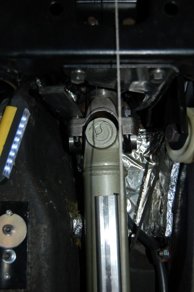
This picture is at the trans tail shaft. The shiny metal piece is magnetically attached to the driveshaft so that I could measure its angle.
It is possible, with I suppose severe rear wheel camber, to get vibration from that mechanism. With so many things coupled together, it is sure is super hard to isolate the source.
It is most definitely offset, The string in this picture is (as I remember) motor centerline to diff centerline
This picture is at the trans tail shaft. The shiny metal piece is magnetically attached to the driveshaft so that I could measure its angle.
It is possible, with I suppose severe rear wheel camber, to get vibration from that mechanism. With so many things coupled together, it is sure is super hard to isolate the source.
It appears that I have to determine if the differential centerline is parallel to the centerline of the car, and if so then the engine/trans centerline must also be parallel to the centerline of the car for the driveline angles to be equal. This should be easy enough with string and a tape measure. That's a good project for today.
Measure the offset distance from a true center-line of the diffy to the trans tail shaft(reference the frame because the engine and diffy are parallel to the frame). Measure the length of the driveshaft and use geometry to determine the angle of the U-joints in this Z configuration. You can also determine the vertical angles by measuring the height differences, since you believe the diffy is 0* to the frame. I've seen tables on the net that indicate maximum total angles vs. RPMs for compound systems.
The engine/trans is centerline is parallel to the centerline of the frame as is the differential, and they are exactly in line with each other, there are no driveshaft angles to correct due to offset since they are both offset an inch to the passenger side. So I was wrong in thinking that I could correct the driveline noise that way. I'm really kind of stumped now.
The half-shafts are the same length(unless I've been really lucky in rebuilding several rear suspensions), so the diffy is centered. The engine is off-set.
The half-shafts are the same length(unless I've been really lucky in rebuilding several rear suspensions), so the diffy is centered. The engine is off-set.
They are, but the pinion itself is offset. I think you can see it in this picture:
I saw that this was so when the centerline of the engine and trans went right through the centerline of the differential housing.
Great article which will help me as well. I ran out to measure mine and its not a digital reading but it looks like trans 3 1/2* down, differential lvl. I will peel this thread and articles back. Many thanks and keep it going.
So I just went out and remeasured everything and my iphone measures the exact same spot a degree different depending on which direction it's facing. I put it on the driveshaft and looking at it from the passenger side it reads 0.01 and then I looked at it from the driver side and it read 1.1. No wonder I can't get it right!
http://www.ebay.com/itm/like/371112895298?lpid=82
Easily good to fractions of a degree and has machined magnetic surfaces.
If I had this to do over again I would get 2 rifle borescope lasers and adjust that way. Yup, a science project.
The essence of this problem is the LS series sit wayup on adapters. An integrated adapter motor mount would put everything back to normal. Come on somebody, make one!
I do wish I had done this with the body off, had I only known.
Easily good to fractions of a degree and has machined magnetic surfaces.
If I had this to do over again I would get 2 rifle borescope lasers and adjust that way. Yup, a science project.
The essence of this problem is the LS series sit wayup on adapters. An integrated adapter motor mount would put everything back to normal. Come on somebody, make one!
I do wish I had done this with the body off, had I only known.
I have a custom frame so I can adjust the LS angle but it is just about the right height for the original tunnel. Is there an optimum angle between the two. My alignment is spot on and I have used this chassis before on my GS. Thanks
Easily good to fractions of a degree and has machined magnetic surfaces.
If I had this to do over again I would get 2 rifle borescope lasers and adjust that way. Yup, a science project.
The essence of this problem is the LS series sit wayup on adapters. An integrated adapter motor mount would put everything back to normal. Come on somebody, make one!
I do wish I had done this with the body off, had I only known.
I'm buying one! And my motor mounts have spacers on them:
And my transmission mount has one too, do I not need them?
Easily good to fractions of a degree and has machined magnetic surfaces.
If I had this to do over again I would get 2 rifle borescope lasers and adjust that way. Yup, a science project.
The essence of this problem is the LS series sit wayup on adapters. An integrated adapter motor mount would put everything back to normal. Come on somebody, make one!
I do wish I had done this with the body off, had I only known.
American Power Train has an trans plate adapter for your C3 cross member.
It's more than a spacer it provides vibration isolation. This bolts to a 3/8" plate which in turn bolts to the motor. The plates form a 'v' which pushes the motor up a bunch.
It's more than a spacer it provides vibration isolation. This bolts to a 3/8" plate which in turn bolts to the motor. The plates form a 'v' which pushes the motor up a bunch.
That is the reason I used solid SBC mounts and moved them around on my thinner adapter plates to get the best up/down forward/back location for my setup. (huge transmission didn't help). I did use a stock rubber trans mount to give it a little room to move. I ended up making a giant caliper to help measure the mounts on the engine and compare width to the frame stands.



















 Great article which will help me as well. I ran out to measure mine and its not a digital reading but it looks like trans 3 1/2* down, differential lvl. I will peel this thread and articles back. Many thanks and keep it going.