
Anyone Have a 1977 Wiring Diagram?
 07-22-2015, 01:58 PM
#1
Team Owner

Thread Starter

If yes, I am looking for the gauge of the wire that hooks up to (+) on the dash voltmeter. I assume ground (-) would be the same.

 07-22-2015, 02:11 PM
#3
Instructor


If I'm reading the diagram right, power is fed to the printed circuit from the 10A gauge fuse with a pink 18ga wire. The ground for the volt meter off the printed circuit is a 14ga black wire.
07-22-2015, 03:28 PM
#4
Team Owner
Thread Starter
I asked the question the wrong way. Apologies. If I installed a voltmeter instead of the existing ammeter in my 1974 what gauge wire would I use for a switched (+) feed? I'm thinking 16-gauge. The ammeter wires would be secured away behind the dash with appropriate insulation so as not to cause any shorts.
07-22-2015, 07:09 PM
#5
Race Director

Member Since: Apr 2007
Location: South Western Ontario
Posts: 11,061
Received 845 Likes
on
721 Posts

The voltmeter is a low current draw so the wire size feeding it really doesn't matter. So, size the wire so the fuse protecting the circuit you're connect to will protect the wire. I'm thinking 16 gauge would work connected to most of the switched circuits in the car where if it did short the fuse would protect it.
07-22-2015, 07:50 PM
#6
Team Owner
Thread Starter
The voltmeter is a low current draw so the wire size feeding it really doesn't matter. So, size the wire so the fuse protecting the circuit you're connect to will protect the wire. I'm thinking 16 gauge would work connected to most of the switched circuits in the car where if it did short the fuse would protect it.
07-22-2015, 08:38 PM
#8
Team Owner
Thread Starter
 07-23-2015, 01:58 AM
#9
Le Mans Master

Member Since: Aug 2006
Location: mount holly NC
Posts: 6,989
Received 1,246 Likes
on
966 Posts
C3 of Year Finalist (appearance mods) 2019
[QUOTE=paul 74;1590109367]Thanks. I may just go to a ground on the frame. Why temp gauge?
Because that is the ground for all the gauges and it will take a short wire, but any good ground will be okay.
Because that is the ground for all the gauges and it will take a short wire, but any good ground will be okay.
07-23-2015, 07:19 AM
#10
Team Owner
Thread Starter
07-23-2015, 12:23 PM
#11
Burning Brakes

I asked the question the wrong way. Apologies. If I installed a voltmeter instead of the existing ammeter in my 1974 what gauge wire would I use for a switched (+) feed? I'm thinking 16-gauge. The ammeter wires would be secured away behind the dash with appropriate insulation so as not to cause any shorts.
18 gauge to and from your voltmeter will be plenty.
07-23-2015, 12:57 PM
#12
Team Owner
Thread Starter
The 1974 does not have a printed circuit...so I will have to wire the voltmeter separately to switched 12V and a dash ground. I am still leaning to 16-gauge.
07-23-2015, 01:41 PM
#13
Former Vendor
Member Since: Aug 2006
Location: Jeffersonville Indiana 812-288-7103
Posts: 76,656
Received 1,813 Likes
on
1,458 Posts
St. Jude Donor '08-'09-'10-'11-'12-'13-'14-'15
Paul... Snag a copy of this too. it's what we call a tracer schematic. Copy the picture and paste it in your "Paint" program. Then save it as a BMP (you won't loose quality). When you open it in paint you can trace wires real easy.
http://repairs.willcoxcorvette.com/1...cer-schematic/
http://repairs.willcoxcorvette.com/1...cer-schematic/
07-23-2015, 02:04 PM
#14
Team Owner
Thread Starter
Paul... Snag a copy of this too. it's what we call a tracer schematic. Copy the picture and paste it in your "Paint" program. Then save it as a BMP (you won't loose quality). When you open it in paint you can trace wires real easy.
http://repairs.willcoxcorvette.com/1...cer-schematic/
http://repairs.willcoxcorvette.com/1...cer-schematic/
07-23-2015, 07:57 PM
#15
Former Vendor
Member Since: Aug 2006
Location: Jeffersonville Indiana 812-288-7103
Posts: 76,656
Received 1,813 Likes
on
1,458 Posts
St. Jude Donor '08-'09-'10-'11-'12-'13-'14-'15
Least I can do Paul and your most welcome.
We use these trace schematics almost every day. Once we trace out a circuit we save them to the main server so we don't have to do it again. But it's a nice way to isolate a circuit for sure.
I've been trying to get all of them up on the site but my time has been limited the last few months.
Willcox
07-23-2015, 08:27 PM
#16
Team Owner
Thread Starter
Least I can do Paul and your most welcome.
We use these trace schematics almost every day. Once we trace out a circuit we save them to the main server so we don't have to do it again. But it's a nice way to isolate a circuit for sure.
I've been trying to get all of them up on the site but my time has been limited the last few months.
Willcox
We use these trace schematics almost every day. Once we trace out a circuit we save them to the main server so we don't have to do it again. But it's a nice way to isolate a circuit for sure.
I've been trying to get all of them up on the site but my time has been limited the last few months.
Willcox
 07-23-2015, 08:38 PM
#17
Former Vendor
Member Since: Aug 2006
Location: Jeffersonville Indiana 812-288-7103
Posts: 76,656
Received 1,813 Likes
on
1,458 Posts
St. Jude Donor '08-'09-'10-'11-'12-'13-'14-'15
I'd either go to the fuse panel or the ignition switch connector at the steering column. I'd prefer the fuse panel though.
So.. your trying to install this in your 74 right? Do you have power windows?
If so the plug for the power windows has a jumper built into it so you could saddle up on that terminal. If you don't have power windows you could use this same lug in the fuse panel for your power source.
I'll take a look at this tomorrow when I get a chance. I need the 74 schematic too. (not on the site just yet).
In the fuse panel below, you have Bat, Acc and Ign... See if you don't have one of those in your fuse block. That's what I would use.

Ernie
So.. your trying to install this in your 74 right? Do you have power windows?
If so the plug for the power windows has a jumper built into it so you could saddle up on that terminal. If you don't have power windows you could use this same lug in the fuse panel for your power source.
I'll take a look at this tomorrow when I get a chance. I need the 74 schematic too. (not on the site just yet).
In the fuse panel below, you have Bat, Acc and Ign... See if you don't have one of those in your fuse block. That's what I would use.
Ernie
Last edited by Willcox Corvette; 07-23-2015 at 08:41 PM.
07-23-2015, 08:54 PM
#18
Team Owner
Thread Starter
I'd either go to the fuse panel or the ignition switch connector at the steering column. I'd prefer the fuse panel though.
So.. your trying to install this in your 74 right? Do you have power windows?
If so the plug for the power windows has a jumper built into it so you could saddle up on that terminal. If you don't have power windows you could use this same lug in the fuse panel for your power source.
I'll take a look at this tomorrow when I get a chance. I need the 74 schematic too. (not on the site just yet).
In the fuse panel below, you have Bat, Acc and Ign... See if you don't have one of those in your fuse block. That's what I would use.
Ernie
I will check tomorrow. Too tired this evening to crawl under the dash. Age has consequences!
07-24-2015, 12:17 PM
#19
Former Vendor
Member Since: Aug 2006
Location: Jeffersonville Indiana 812-288-7103
Posts: 76,656
Received 1,813 Likes
on
1,458 Posts
St. Jude Donor '08-'09-'10-'11-'12-'13-'14-'15
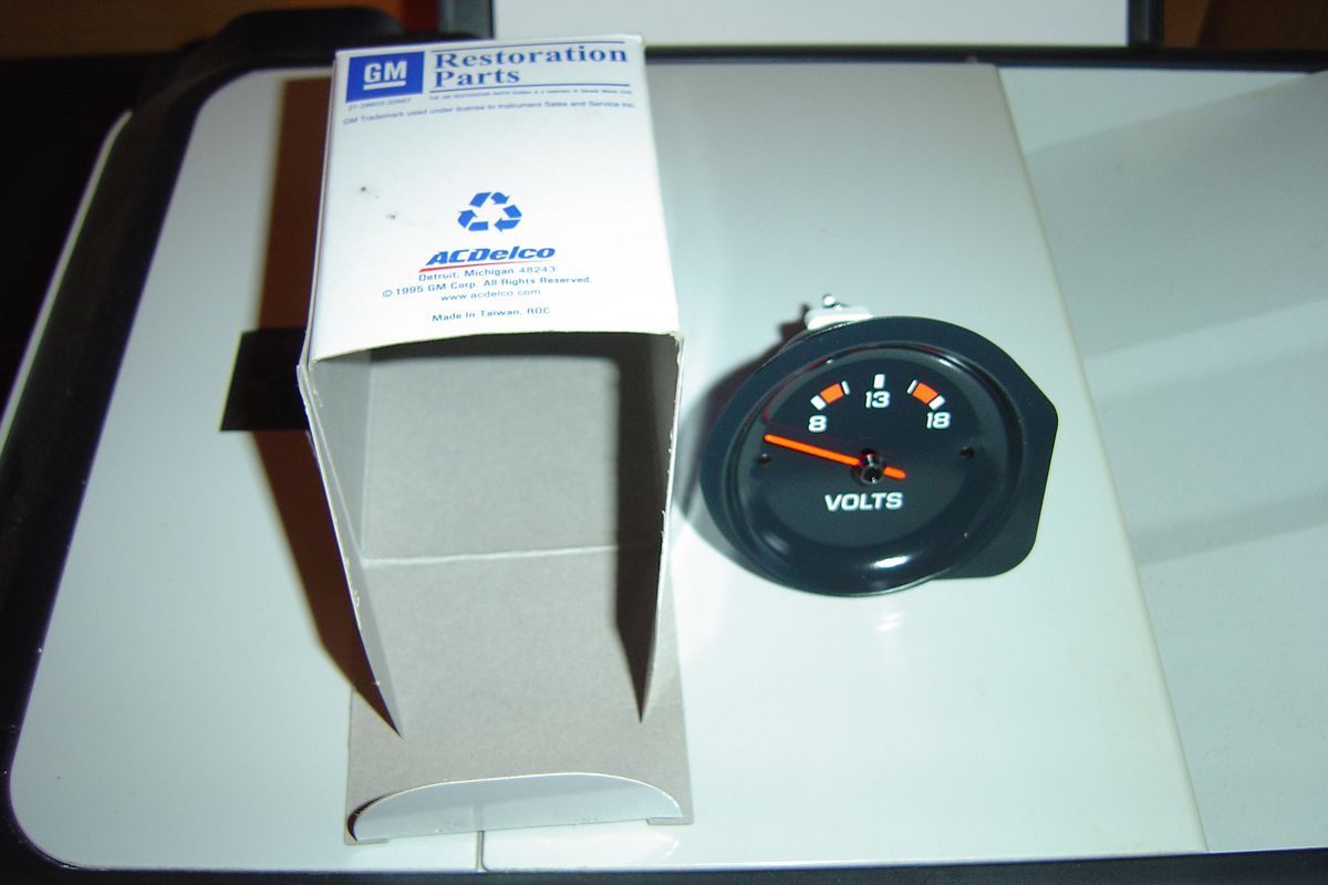
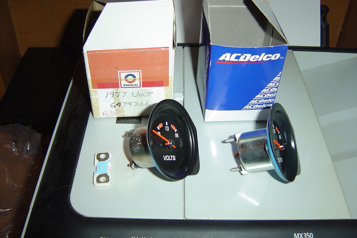
Paul... are you installing that gauge in your car? If so, below is how you would wire it....
The switched voltage you can pick up from the ign or the Accy lug in your fuse panel. Both are switched. If you have power windows you'll have a jumper like the one pictured below and you can jumper in on that one too. You have some options for sure.l


The switched voltage you can pick up from the ign or the Accy lug in your fuse panel. Both are switched. If you have power windows you'll have a jumper like the one pictured below and you can jumper in on that one too. You have some options for sure.l
07-24-2015, 01:23 PM
#20
Team Owner
Thread Starter
Yes, the objective is to replace the ammeter in my 1974 with the voltmeter.
I currently have my daytime running lights (DRLs) hooked into the ACC lug. I do have power windows and that is hooked into the IGN lug with the wire and jumper as you have shown. The jumper is unoccupied so it looks like that is the target for the 12V voltmeter power source although I do wonder if the amperage in that heavy gauge wire might be too much for the meter. My thanks to you for your informative reply!

I currently have my daytime running lights (DRLs) hooked into the ACC lug. I do have power windows and that is hooked into the IGN lug with the wire and jumper as you have shown. The jumper is unoccupied so it looks like that is the target for the 12V voltmeter power source although I do wonder if the amperage in that heavy gauge wire might be too much for the meter. My thanks to you for your informative reply!
Last edited by Paul L; 07-24-2015 at 01:37 PM.