

power window switch for linear actuator


Thread Starter
Burning Brakes


Joined: Sep 2014
Posts: 775
Likes: 98
From: carroll ohio


Le Mans Master


Joined: Aug 2006
Posts: 7,419
Likes: 1,555
From: mount holly NC
2025 c3 ('74-'82) of the Year Finalist - Unmodified
2019 C3 of Year Finalist (appearance mods)
The switch that '75 suggested will work just fine.
You can protect that circuit by supplying 12 volts positive from the circuit breaker for the power windows (in the engine compartment) by taping into the feed side.
You can pick up the ground next to where you mount the switch.
You can protect that circuit by supplying 12 volts positive from the circuit breaker for the power windows (in the engine compartment) by taping into the feed side.
You can pick up the ground next to where you mount the switch.
Thread Starter
Burning Brakes
Joined: Sep 2014
Posts: 775
Likes: 98
From: carroll ohio
thanks for the reply.i do not know what wire goes to each pin on the switch. i had my ohm meter on each pin and across the pins but am not sure which pin should have which wire to it. i am not using the power window harness for this app. i am using this switch to activate a linear actuator. this forum was kind enough to show a DPDT switch which i understand how to install.i would like to bench test this switch anyway and maybe work some travel limiters into the mix. denny
The switch that '75 suggested will work just fine.
You can protect that circuit by supplying 12 volts positive from the circuit breaker for the power windows (in the engine compartment) by taping into the feed side.
You can pick up the ground next to where you mount the switch.
You can protect that circuit by supplying 12 volts positive from the circuit breaker for the power windows (in the engine compartment) by taping into the feed side.
You can pick up the ground next to where you mount the switch.
Le Mans Master
Joined: Aug 2006
Posts: 7,419
Likes: 1,555
From: mount holly NC
2025 c3 ('74-'82) of the Year Finalist - Unmodified
2019 C3 of Year Finalist (appearance mods)
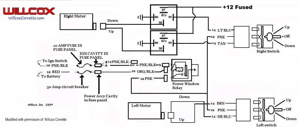
With your ohm meter set for continuity attach one lead to the center left terminal. With the switch UP you will have continuity to the top left terminal then push the switch to the DOWN position and you will have continuity to the bottom terminal.
The right side works the same way.
The switch does not come with the wires that make the 'X'. You have to solder a short wire from the top left to the bottom right and do the same from the top right to the bottom left.
You can supply power to the switch from the battery or the horn relay or any other convenient place that to choose, but you need to protect the switch with a fuse, I only suggested using the power window circuit breaker because if you use that you will not need a separate fuse.
Thread Starter
Burning Brakes
Joined: Sep 2014
Posts: 775
Likes: 98
From: carroll ohio
thank you very much.it's cold here so i'll start this project inside this weekend. i have seen some of the DPDT switches with a buss bar that connects to make an X. i'll also see how the aftermarket switch holds up.many say they are junk. ohm meter set for continuity attach one lead to the center left terminal. With the switch UP you will have continuity to the top left terminal then push the switch to the DOWN position and you will have continuity to the bottom terminal.
The right side works the same way.
The switch does not come with the wires that make the 'X'. You have to solder a short wire from the top left to the bottom right and do the same from the top right to the bottom left.
You can supply power to the switch from the battery or the horn relay or any other convenient place that to choose, but you need to protect the switch with a fuse, I only suggested using the power window circuit breaker because if you use that you will not need a separate fuse.[/QUOTE]
Former Vendor
Joined: Aug 2006
Posts: 76,656
Likes: 1,851
From: Jeffersonville Indiana 812-288-7103
St. Jude Donor '08-'09-'10-'11-'12-'13-'14-'15
OK- let me be a little more specific- the contacts on the switch will arc- the arc will create contact erosion...the switch will cease to operate...
Often refereed to as "burntup" or "Itdontworknomore"
I'm going to guess 10-12A at stall
Well- there's very few OE GM parts for these cars anymore- most are just licensed under GM- and made in China. Just do a search on replacement power window switch problems... actually put together a drawing-w/ permission from Wilcox on how to solve PW switches from-pardon my term-burning up.
I'm actually using Jaguar power window switches with Bosch relays and a Spal motor.
Let's see...BMW engine....Geo alternator... Mercedes Benz throttle linkage....Ford headlight motors....Subaru oil pressure P/U...Dodge serpentine pulley...Cadillac Escalade Cupholder....Mitsubishi Defroster Vents...Volvo sliding console...and a host of aftermarket parts.
Yesterday I saw this post and started drawing up a quickie schematic... then it dawned on me that there was already one out there on this forum...
So I looked.... And looked... and looked some more to no avail.. I couldn't find it.... but knew it was there.. Richard's post of my diagram modified kept sticking in my mind but I kept coming up blank and for some reason I couldn't find it....
So Richard.. I think I'm going to jack my diagram back with your mods (with credit) and put this on the repair site so I can find it when needed.. lol
Ernie


