When you click on links to various merchants on this site and make a purchase, this can result in this site earning a commission. Affiliate programs and affiliations include, but are not limited to, the eBay Partner Network.
Electrical help, advice, and input requested alternator..
I posted this on the C2 site it appears there is more people modifying electrical systems on this forum.
I am installing a new non stock alternator rated at 140 AMP's with an internal regulator. I will be wiring the alternator as a 3 wire alternator using the adapter kit from Lectric Limited. 140 AMP pulley changed to stock pulley to keep belt from jumping off, I'm certain this will lower the amount of AMP's put out by the alternator. All wiring harnesses are new , less than 2 years old.
I have added Vintage Air AC, SPAL puller fan, and a MSD system. I don't want to run AC and Fan off the battery, planning to use a buss bar to power the AC and fan. Also attached to the bus bar will be a 8 ga wire from the alternator and a 8 ga wire from the buss bar to the horn relay. I want to run an additional 10 ga wire (or 8 or 6 ga possibly) from buss bar to the starter solenoid , not sure if this is the right thing to do. I have attached a wiring diagram showing my initial plan.
I was planning to leave all stock wiring untouched, with exception of stock regulator wires.
When I added the puller fan I used the brown wire from the voltage regulator as my hot wire for the fan temperature sensor (on 195 off 175). Don't know if this is going to give me any issues with the 3 wire set up. I guess I could of gotten my power from the horn relay buss bar, but wasn't thinking.
Looking for electrical help/advise, do not want to burn this thing up just finished frame up restoration.
Thanks
I am installing a new non stock alternator rated at 140 AMP's with an internal regulator. I will be wiring the alternator as a 3 wire alternator using the adapter kit from Lectric Limited. 140 AMP pulley changed to stock pulley to keep belt from jumping off, I'm certain this will lower the amount of AMP's put out by the alternator. All wiring harnesses are new , less than 2 years old.
It won't lower the max output -just the RPM it is attained- Smaller size Alt pulley spins faster- and puts out more power when you really need it- at idle.
I have added Vintage Air AC, SPAL puller fan, and a MSD system. I don't want to run AC and Fan off the battery,
Ummm- if you read the Vintage Air directions THEY say wire directly the the battery pos and neg- as their control module does not like surges either...
planning to use a buss bar to power the AC and fan. Also attached to the bus bar will be a 8 ga wire from the alternator and a 8 ga wire from the buss bar to the horn relay. I want to run an additional 10 ga wire (or 8 or 6 ga possibly) from buss bar to the starter solenoid , not sure if this is the right thing to do. I have attached a wiring diagram showing my initial plan.
I was planning to leave all stock wiring untouched, with exception of stock regulator wires.
When I added the puller fan I used the brown wire from the voltage regulator as my hot wire for the fan temperature sensor (on 195 off 175). Don't know if this is going to give me any issues with the 3 wire set up. I guess I could of gotten my power from the horn relay buss bar, but wasn't thinking.
Looking for electrical help/advise, do not want to burn this thing up just finished frame up restoration.
Thanks
Think of the Alternator as your income- and the battery as your bank account. You don't want your mortgage payment coming out of your paycheck...The battery does more than just start your car- it stabilizes the voltage and filters the rippled (AC current) left over by the rectifier in the alternator (MSD & electronics like that as I noticed you did connect that to the battery).
And looking at your diagram- if for some reason the 8GU to the buss bar fails or loosens up the stock 14GU wire will be toast. Electricity follows the path of resistance- but rather ALL paths...
If you are inquiring about a C2- the battery under the hood makes it a simple short no brainer wiring job to go to the battery.
BTW- upgrading- changing the wires your ammeter will NOT read correctly.
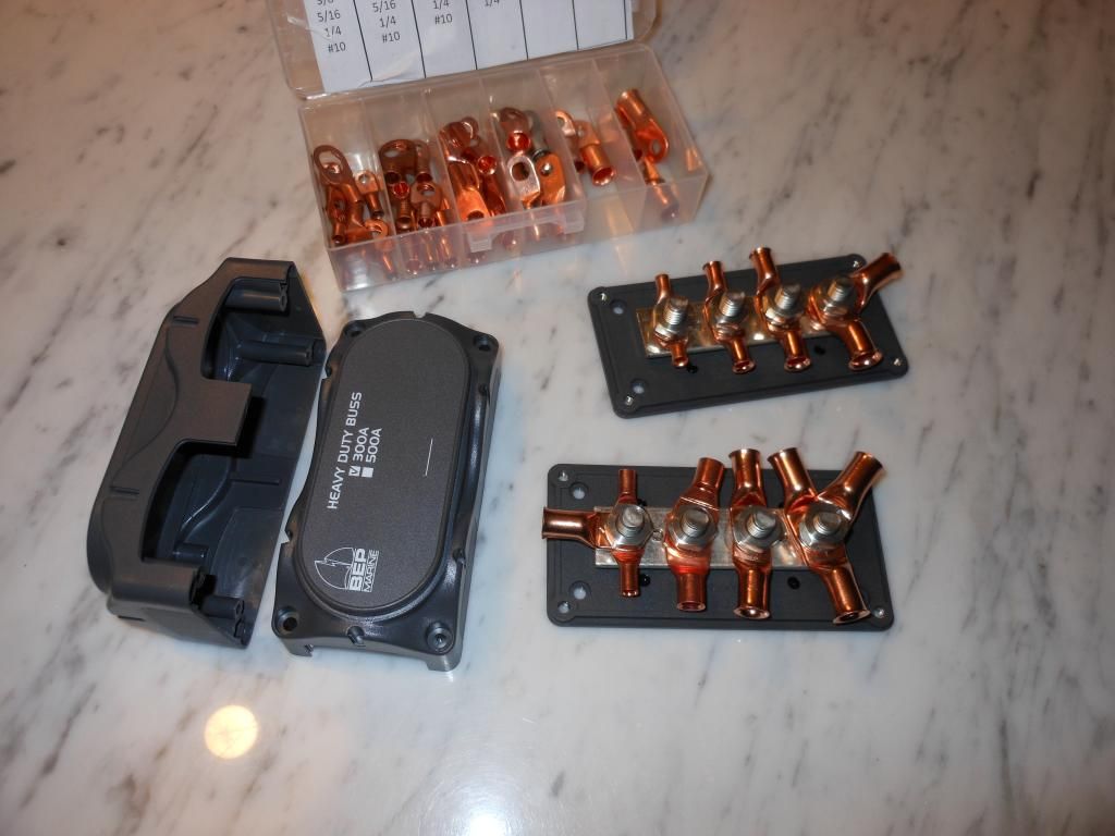
Here's nice SS buss bar I used- for Marine applications-
Last edited by Richard454; Feb 2, 2016 at 10:55 AM.
I share your philosophy on not hacking up the existing harness and adding the new heavy electric loads to a buss bar fed by the alternator.
I'm guessing the brown wire is only to energize the relay? If so, it's a fraction of an amp so no problem.
I think adding the wire from the alt to the starter solenoid is a good idea since the MSD is hooked to the battery. Otherwise, the voltage drop in the crusty old wire from the factory Jblock to the solenoid could make the 14.4V from the battery barely keep the battery up. And worse yet, if the fan and AC are on when the engine stalls, all of that power (possibly 30-50 amps plus the rest of the car's consumers) has to be supplied through the existing 10ga from the Jblock to the solenoid. The terminals won't last long like that. I would run a 6 or at least 8 ga there.
One change I would make from Richard's drawing is power the MDS off the buss bar. No need to put that extra up to 10A on the.... Oh wait, it's still powered from the 1 ga from the battery.
Which ever is easier. Assuming his pic includes a #6 wire from the battery to the buss bar. You need a solid connection between the battery/alt/ and buss bar. If you omit the bat-buss bar wire, when the engine is off and hot, the full load of the fan and maybe even the AC is going through the 10ga wire through the original harness until the engine is runnign and the alt charging.
I would use a 6ga wire to the busbar and 4 ga to the starter. Consider placing a 250 amp fuse for the 4ga pure copper or 2ga CCA wire to the starter lug for alternator over charge protection. On the MSD, use MSD pt# 8830 to filter out EMI as it will affect other electronic components. ie - Vintage Air ECU. Leave the MSD outside the firewall if at all possible and as far away from the Vintage Air ECU or any ECU for that matter. Yes 4ga sounds large, but will prevent voltage fluctuation that could compromise the function of all components.
One change I would make from Richard's drawing is power the MDS off the buss bar. No need to put that extra up to 10A on the.... Oh wait, it's still powered from the 1 ga from the battery.
Which ever is easier. Assuming his pic includes a #6 wire from the battery to the buss bar. You need a solid connection between the battery/alt/ and buss bar. If you omit the bat-buss bar wire, when the engine is off and hot, the full load of the fan and maybe even the AC is going through the 10ga wire through the original harness until the engine is runnign and the alt charging.
Sorry throwing the pic together - the MSD is connected to the buss bar.
Yes- the buss bar should basically be in theory the battery terminal- close - connected w/ large gauge wire.
You would also run the Vintage Air directly to the buss bar as per the directions= to the battery.
If I'm not mistaken the 10gu is a fusible link-so if the buss bar somehow comes undone it will burn the link... If you think that is going to happen- you can always use a 50A maxifuse at the alt to the factory wire...Problem solved.
Originally Posted by YUSLOW
I would use a 6ga wire to the busbar and 4 ga to the starter. Consider placing a 250 amp fuse for the 4ga pure copper or 2ga CCA wire to the starter lug for alternator over charge protection. On the MSD, use MSD pt# 8830 to filter out EMI as it will affect other electronic components. ie - Vintage Air ECU. Leave the MSD outside the firewall if at all possible and as far away from the Vintage Air ECU or any ECU for that matter. Yes 4ga sounds large, but will prevent voltage fluctuation that could compromise the function of all components.
CCA is awful stuff...bend it a couple time and it breaks..you even pointed out that you hve to go to a larger gauge for the same current capacity...So larger gauge CCA is just a little bit less than the smaller OF copper wire.
250A overcharge? The only time overcharging will really cause a problem is when the diodes /rectifier have broken down and feeding the battery AC. Alternator on a good day will only put out 140A
As far as EMI- running the wires in parallel is a no-no- if they come near each other cross them perpendicular. They are both in a metal- shielded box- should be ok.
I do like using large wire myself- I'm running 1/0 GU...
Wow....6ga to the horn relay bussbar? That's gonna be a pretty crazy tight terminal at that location. I modify the OEM redundant charging system as follows:
8ga from 140A output post to a GM style junction on the firewall (mainly for convenience)
8ga from junction to battery
8ga from junction to horn relay/bussbar
8ga from bussbar to firewall bulkhead (this is my new interior power lead, up from 12ga stock)
Now, with this setup the alternator remote voltage sense wire (large red wire on plug) goes to the GM style junction because this is the most common point from where all voltage drop can be measured from-this stabilizes the entire charging system.
Now, I pulled a 10ga power lead from the horn relay bussbar and with this I added a relay bank to power the following:
Axial style stock AC compressor (thereby relieving the switch from carrying it)
Idle stop trigger (using a Holley aftermarket type)
Headlights (both low and high beam)
The results before the charging system upgrade harness (using the same 140A alt too) I measured with the car running:
14.2V @ the output post
13.8V @ stock horn/bussbar
12.8V @ the headlights (low beam)
12.6V @ the BAT inside on the stock 1970 glass fuse panel
The terrible GM redundancy in wiring is evident with the extreme voltage loss-this is why even "restoration" harnesses lack in performance because if no modern upgrades are integrated why put up with it? New wiring is nice but if it keeps with the GM routing....then....???
Now, after the charging system wiring upgrade I measured:
14.3V @ alt output post
14.3V @ stock horn/bussbar
14.2V @ headlights (low beam)
14.2V @ the BAT inside on stock 1970 glass fuse panel
I then kept headlights on, wipers on high, AC on high, turned the amplified stereo system up, depressed the brakes, held drivers door open and ran the power windows up. My voltage as measured @ the inside BAT fuse location only varied by .2V the entire time-14.0 to 14.2 the entire time! Everything works faster, lights were brighter and NO dimming when AC kicks on high. Very stout charging system on a relatively simple upgrade over stock....and other than my upgrade the vehicle wiring is 100% stock too!
I didn't catch the CCA note. That stuff is no good for automotive use.
I exclusively use GXL or TXL wire, or sometimes for the really heavy stuff, welding cable or Marine Grade. I really like the Marine 50A-150A re-settable circuit breakers. Then you can turn off things and work on them rather than pulling a battery terminal.
AND, don't solder terminals unless the wire is very well supported and strain relieved. The solder will wick into the wire and cause a stress riser where it will bend, work harden and break.
Here's another problem I often see. People put a 1 wire alternator on a car, then feed everything with a single #10 or#8 wire. Then alt may put out 14.4 volts, but the battery only sees 12.4 or so, and is never really charging, and eventually goes dead. THe reason the factory never has adn never will use a 1 wire is the voltage drop. If you correctly hook the sense wire near or straight to the battery, if there is a voltage drop due to every electric consumable being on, the sense wire will up the alternator output to 15-15.5 volts so that the battery get's its 14+ volts needed to actually charge.
I just laid out an exact routing of how to mod a stock system using 8ga wire as the main support load for everything under hood with actual measurements-your argument is not valid. OEM don't require crazy large wiring even on late model stuff-no need to get crazy on older stuff either-rather use the KISS principle and route the wiring in a more practical sense.
The remote voltage sensing lead needs to be placed downstream of the alternator output at or near a common junction from where everything can pull power from. The buffer characteristics of the battery itself lend the alternator to be "blinded" by increased voltage demands placed on the electrical systems. Other than the Buick GN's I'm not aware of any GM alternator attempting to put out any more than 14.4V under any circumstance assuming the alternator is not faulty.
I agree the 1-wire type alternators have no place under any hood mainly because they are somewhat the Neanderthal of alternators - they may work but are terribly inefficient. Sticking with the tried and true 3-wire setup is the best course to take.
OEM doesn't use super heavy #2 wire because it does use remote sensing. And a 1 wire is every bit as efficient as a 3 wire. In fact, it is a 3 wire where the excite and sense wires are all tied together at the output terminal.
And yes the alternator will output more than 14.4 if the sense wire is reading less than adequate. Try using a 20ga wire from the alternator output to the load, so it's dropping 3 volts and everything is running on the battery. That's why there IS a sense wire. If it never put out more than 14.4 V, there would be no need to have a sense wire connected anywhere other than the output.
You'll also notice that the newer the car, the higher current the alternator, and the wire connected to it. #8 is fine up to about 60A intermittent, less in my opinion. Once you add electric power steering, electric fans, a honking 500W stereo, power windows, seat heaters, and a 20A fuel pump, a #8 wire on a 140A alternator will drop 5V and look like the element in your toaster oven. For a T bucket with a carb, #10 is fine.
OP, PM me for help, a little late tonight, age 71 here, old hotrodder for some decades, my '72 has a serp drive and spals fans, and so to dump the V belts as the old SAE V pitch is really hard to find these daze, the metric pitch of the V is much wider so putting a modern metric belt on the old pullys will make the flat back side of the belt go concave because belt is riding on the upper edges only, not the entire surface of the V, fast wear out, squeels on heavy loading.....I have to ASSume you have a CS144 alt......that can be hooked up with one brown/stock color wire to the regulator....
I get to the rest of the electrical stuff another time......


 DSCN5379 by Richard Hayes, on Flickr
 DSCN5091 by Richard Hayes, on Flickr
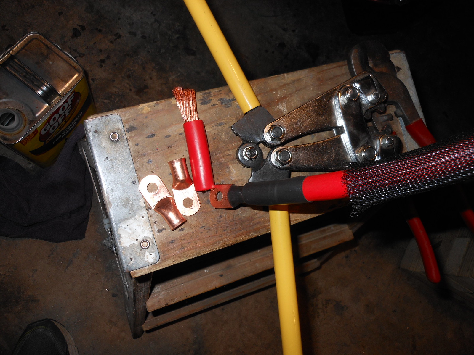 DSCN5079 by Richard Hayes, on Flickr


