When you click on links to various merchants on this site and make a purchase, this can result in this site earning a commission. Affiliate programs and affiliations include, but are not limited to, the eBay Partner Network.
I'm planning to get the free O'Reilley's cam degree kit tool rental this weekend and degree my cam and measure for my pushrod length.
I've read about the procedure a good few times and watched a number of different videos so far, but I have no doubt that I'm going to have questions.
I have checker springs and the adjustable CompCams Magnum pushrod length checker, but I don't have the blue plastic geometry checker / fake rocker tool -I'll just use the black marker through the center of my actual rocker method.
I have one of the piston stops that goes through the spark plug hole.
I have silly putty for piston to valve clearance checking.
I do not have a dial indicator gauge and I don't believe the kit comes with one. -I'm going to have to use the piston stop method.
My hydraulic roller rockers are all soaking in new motor oil right now and I won't install them until right before I'm ready to go.
The free O'Reilley's kit isn't a large diameter degree wheel but it's way better than not degreeing the cam at all and it's not like I can adjust it less than one sprocket tooth, anyway.
Right now my first question is regarding whether to install head gaskets to do this or not. (Do I put the heads on with the steel shim (0.015" compresssed) gasket and just very lightly torque the head studs for this, or do I just assume that 15 thousandths is going to be a very negligible difference for cam timing, pushrod length, and piston to valve clearance?)
In this, determining PR length, I think the 0.015 difference is rather insignificant ... but ... couldn't you use a "faux" gasket ... cut a few strips of cardboard/cereal box etc about same thickness ... lay em across deck ... as a shim ... set head atop & snug a few stud nuts ... proceed as though you had a real gasket ... why not?
Assuming this is an SBC, simply add the compressed head gasket thickness, in this case 0.015 inches to the length of the pushrod that you come up with. Totally linear. A little more complicated for big blocks.
Have the putty in one cylinder and install one head
Don't even worry about cam degree or push rods until you have the heads in place and snug it with just a few bolts
Install the piston CCW at say 10 degree BTDC and use a sharpie to mark the degree wheel with your pointer. Rotate CW back to the piston stop and mark the degree wheel at the pointer. Do the math and see if your cam matches the cam card
If you have a multi key way timing set you can dial in the cam to less than a couple of degrees and then you have to decide whether you want a touch of advance or retarded
Retarded gives you a lower peak power, but a broader tq curve that gives you a higher average across the rpms. I install mine with retard.
Then do pr length. Once everything is done. Rotate and measure the clay
I have one of the piston stops that goes through the spark plug hole.
Thanks,
Adam
Since the heads are off try using a 'bridge' across the cylinder. I've only ever checked a few TDC's and found theb bridge method, being perpendicular to the piston face, to be easier. IDK YMMV
Have the putty in one cylinder and install one head
Don't even worry about cam degree or push rods until you have the heads in place and snug it with just a few bolts
Install the piston CCW at say 10 degree BTDC and use a sharpie to mark the degree wheel with your pointer. Rotate CW back to the piston stop and mark the degree wheel at the pointer. Do the math and see if your cam matches the cam card
If you have a multi key way timing set you can dial in the cam to less than a couple of degrees and then you have to decide whether you want a touch of advance or retarded
Retarded gives you a lower peak power, but a broader tq curve that gives you a higher average across the rpms. I install mine with retard.
Then do pr length. Once everything is done. Rotate and measure the clay
I thought it was "Advanced" that gave you the low-end grunt. And "Retarded" was for the upper / high RPM band, like 4,000- 8,000.
And I thought it was Lobe Separation Angle that determines the width or lack of width for torque curve.
Most street cams have 4* of advance built in for that off-idle punch. That's what most cam customers want, is grunt, right out of the box.
The timing chain crank sprocket usually has three choices of keyways:
straight up or zero.
4* advance
4* retarded
Well... I got a bunch of things done but I'm still stuck trying to figure out pushrod length.
At first the heads wouldn't actually go on over the studs; I did sinch the studs down using the alan heads a tiny bit more than "finger tight" -this made the studs EVER SO SLIGHTLY not perfectly straight up and down- as soon as I loosened them back to finger tight no problems there.
I've honestly been dreading measuring pushrod length for a long time and planned to have a professional "on standby", but I've managed to power through and figure everything else out so I didn't... Now I'm starting to regret that.
I'm going to go watch a number of different videos on pushrod length again and try to document a detailed step-by-step procedure and I'll try again, but there's just so many variables it's really pretty daunting.
One thing I'd really like to understand is how I'm supposed to rotate the engine a few times to take a look at the wear pattern with roller lifters- won't rolling the engine over a few times squeeze all the oil out of the hydraulic lifters and cause them to collapse and screw up the test? (even with checking springs?)
Note: I don't have any oil in the engine at this time but I have the lifters immersed in my break-in oil.
One thing I'd really like to understand is how I'm supposed to rotate the engine a few times to take a look at the wear pattern with roller lifters- won't rolling the engine over a few times squeeze all the oil out of the hydraulic lifters and cause them to collapse and screw up the test? (even with checking springs?)
Adam
Substitute a lifters with dummy/solid lifter of the same height. Its take a fait amount of pressure to squeeze down a hydraulic lifter. Straub/Foxwell video pretty much nails push rod length...no need to check 'marks'.
Substitute a lifters with dummy/solid lifter of the same height. Its take a fait amount of pressure to squeeze down a hydraulic lifter. Straub/Foxwell video pretty much nails push rod length...no need to check 'marks'.
I don't happen to have a random solid lifter version of my hydraulic roller lifters laying around. I just have my hydraulic roller lifters.
I did just find the video you're referencing though! Thanks!
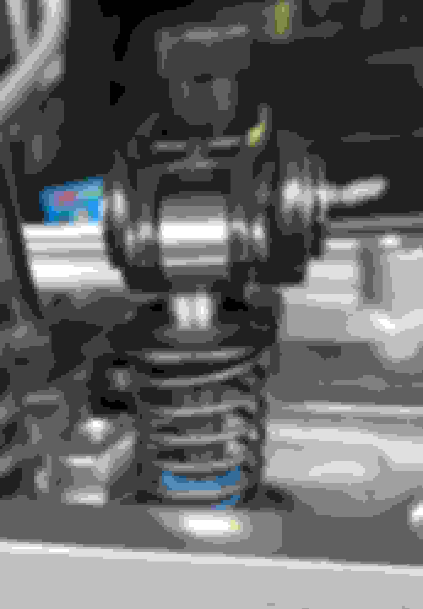
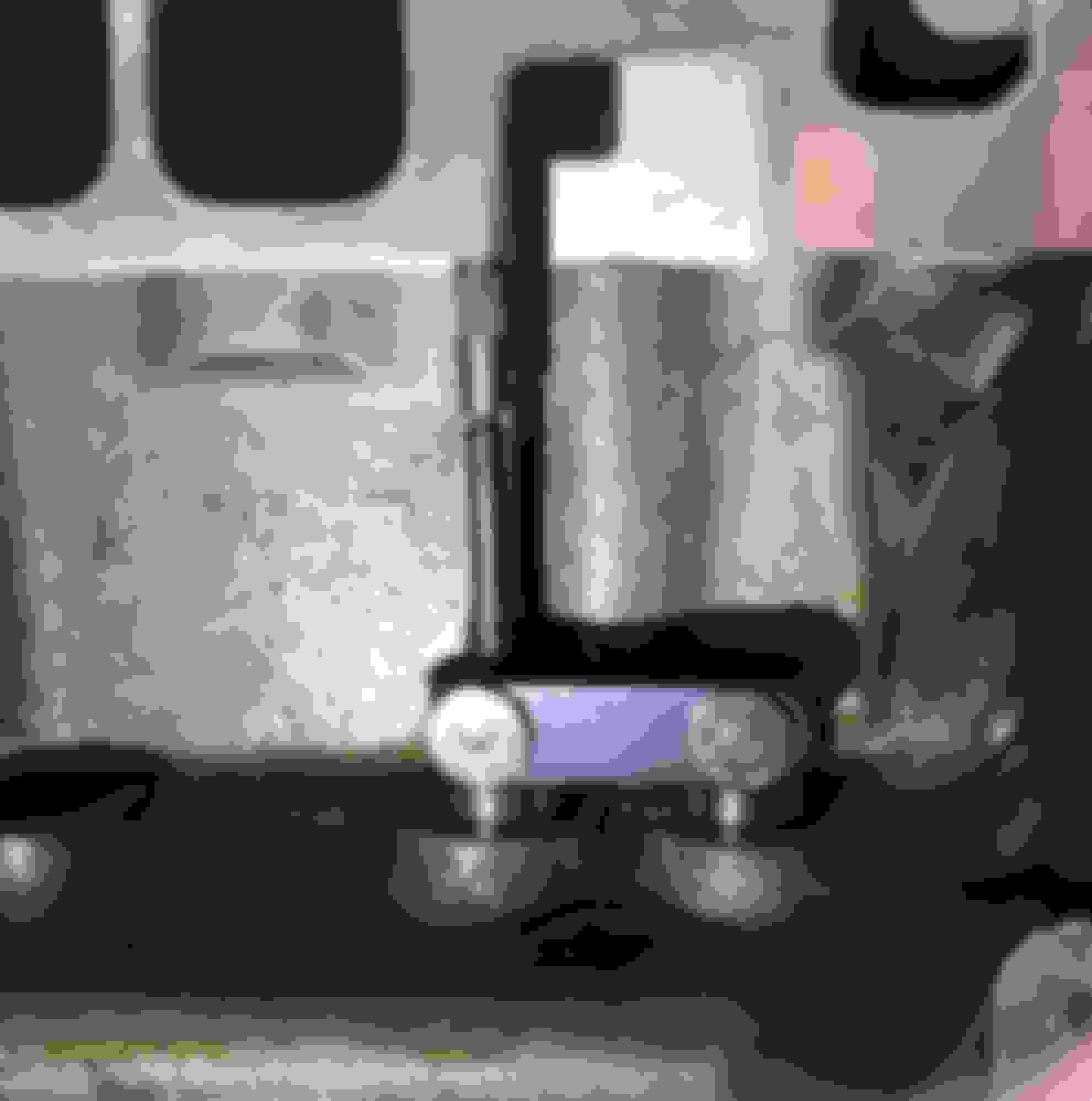
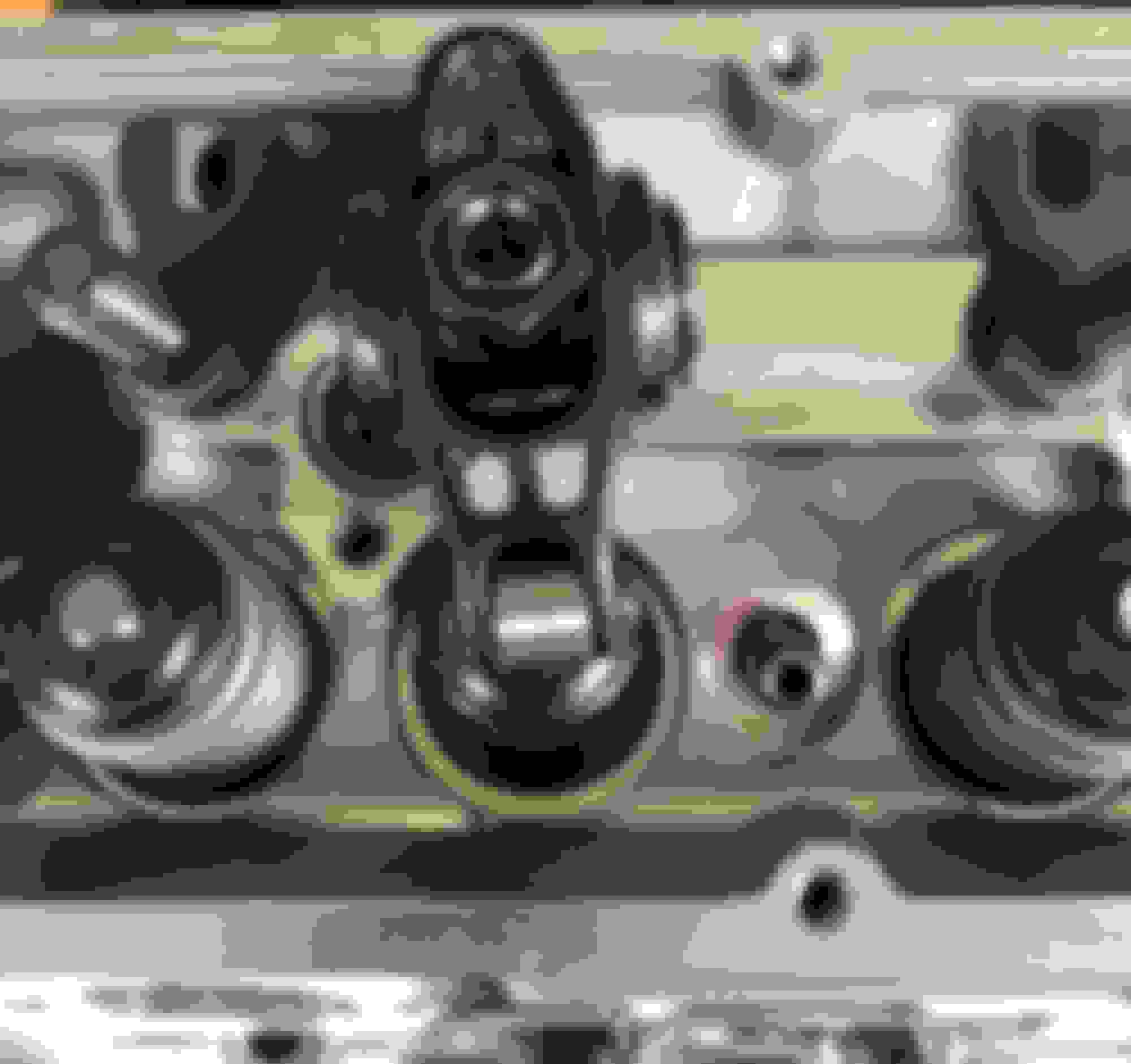
Here's a couple pictures of my rocker from yesterday: this is cylinder #1 intake valve:
Roller is NO WHERE NEAR centered on the valve tip side-to-side. Look at how off center it is!
Is it ok that it's so far off center? (It doesn't seem like there's any way to make it more on-center side-to-side). The length checker pushrod is in the lifter cup and in the rocker cup.
I'm also just not sure how high up on the rocker stem to put the rocker, it seems like you can have roughly the same rocker geometry with the rocker down lower on the stud with a shorter pushrod or up higher on the stud with a longer pushrod...
Prefer using the head gasket and torquing it down (or close anyways) May as well check it the way it will actually run.
You dont need to go buy another one either
Here's a couple pictures of my rocker from yesterday: this is cylinder #1 intake valve:
Roller is NO WHERE NEAR centered on the valve tip side-to-side. Look at how off center it is!
Is it ok that it's so far off center? (It doesn't seem like there's any way to make it more on-center side-to-side). The length checker pushrod is in the lifter cup and in the rocker cup.
I'm also just not sure how high up on the rocker stem to put the rocker, it seems like you can have roughly the same rocker geometry with the rocker down lower on the stud with a shorter pushrod or up higher on the stud with a longer pushrod...
(Going to watch the Straub video now...)
Adam
Adam,
You need to loosen the rocker studs and try to reposition the guide plate enough to line up the valve stem tip to the rocker tip then tighten the stuids back down.
also, isky etc make split guide plates ...one plate's in 2 pieces ... they sort of key together ... MUCH easier to align ... once aligned, you tack weld it into one piece.
Adam,
You need to loosen the rocker studs and try to reposition the guide plate enough to line up the valve stem tip to the rocker tip then tighten the stuids back down.
well now that you say that, it makes sense and seems completely obvious!
I used a black sharpie and painted the ends of the valves. Put it together and turned the crank a couple of revs. Pulled it apart to see the contact pattern. Centered up on the valve. Took a couple of attempts to get the contact where I wanted it.
Is this the same with stamped steel rockers? it's easy to draw a center line on a roller rocker, but I think on a stamped steel rocker it may be a little harder.

 04-04-2019, 06:11 PM