When you click on links to various merchants on this site and make a purchase, this can result in this site earning a commission. Affiliate programs and affiliations include, but are not limited to, the eBay Partner Network.
Has anyone drawn a schematic for the 69-72 wiper system by itself.......I have two wiring diagrams, the GM one and the Doc Rebuild one......the problem is that there is so many things in this system, I can't see the system by itself for troubleshooting.......
I could draw it out myself....but maybe someone has already?
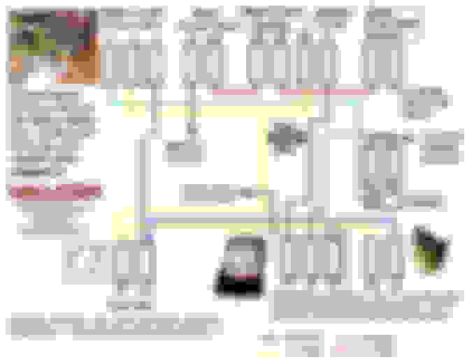
Here's a simple one I
put together for what the wires actually do at the wiper-
Thank you too for that.......both are saved to my Vette files
The system I am working on is jacked.....hasn't worked in 20 years....so I went to the usual suspects, the door switch, wiper motor, wiper switch, wiper relay.......and actually have power tot he blue wire at the motor. It was giving my Vulcan Mind Melt to try to "see" the system in my head...so I could follow the paths and come to a determination. The blue wire has to be in contact with power somewhere....and I will find it, but now I have a good understanding of how this switched ground disaster of a system works
Richard...you have an amazing amount of documentation.....very commendable. I tried to do this in the Vintage Honda universe years ago but **** always ends up getting lost or scattered......after a while it is more of a job to document than actually performing the work......and people are always on me to fix their junk......so no time for it anymore
I plan to do engines and carbs when I retire some day though, maybe then I can go all OCD on it again......
Thanks,
Jebby
Thank you sir-
Trust me- it's a lot easier to keep up with stuff on my computer versus the shop...
I am still working on a virtual search engine to find a tool or part in my garage!!!...Wouldn't that be cool!!!
I used the wilcox wiper diagram on my 71 recently and a forum member emailed me a full car schematic too. There was definitely some mind melting involved. The thing that made it extra confusing was that the wiper switch gets ground from its mounting screws. With the switch hanging by the wire for testing purposes the system does not work. The relay under the shift plate definitely adds to the confusion too. With power to the wiper motor you should be able to clip a ground wire to the appropriate terminals and get high and low speeds working.
Finally got the vacuum door going yesterday after finding a stuck tach vacuum solenoid.
Slightly off topic
On the relay black wire that connects to "dash cluster ground" (#7 on Willcox diagram) where physically does that go?
Thx
M
Im not sure but I added a ground from wiper switch to the frame surrounding radio just to be sure the black wire to dash gauge cluster was not going to mess up my wipers if it is or becomes loose. I think its way back behind the gauges somewhere.
I'm just trying to find where that wire goes in the circuit diagram.
All of the gauge and console plates are "grounded" and I know there's a tab on the shift console that has a ground wire, also on the tach and speedometer but I can't recall where the one for the gauge console was located and I didn't really want to pull it back out to check.
This connection is missing on the chassis manual for the 72
And I really believe the one that I have that goes nowhere is the supplied ground wire to the center gauge console. On that 71-72 diagram it's not showing a spade connector, like it does for the shifter console, speedo, tach, etc. so it might have been a loop that went onto one of the bolts for the bezel ??? I just can't recall where it went and none of my pictures show it, or at least that I can recognize.
I just can't recall where it went and none of my pictures show it, or at least that I can recognize.
M
I seem to remember a ground wire attached to the driver's side hinge pillar, somewhere above or behind the kick panel? I could be wrong, the ole memory ain't what it use to be!
Yes that is the main ground point for the whole dash harness, I just can't remember (damn aluminum pots) how / where the connection is for the center gauge cluster.
The tach and speedo have spade connectors for their ground wires to connect to
The shifter console has a spade connector for the ground wire there
What grounds the center gauge bezel for all the lights wiper switch etc???
Don't see anything in the AIM either but something grounded it and GM didn't usually use the gauges or radio as a ground point
M
Willcox diagram shows that the center tab is indeed grounding the gauge cluster and therefor seems to be the ground point for the entire center bezel... I take my comment about GM using gauges for grounds back
The ground wire for that is connected to the main dash ground harness so that makes sense
The "lost" wire on my diagram must be the one that goes to the screw at the drivers door hinge pillar area


 That is a great diagram and I also find it hard to find the tech info I'm looking for on the Willcox site...