When you click on links to various merchants on this site and make a purchase, this can result in this site earning a commission. Affiliate programs and affiliations include, but are not limited to, the eBay Partner Network.
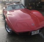
Hi all, I am getting ready to swap a CS144 from a 96 impala onto my 76 corvette because after a few electrical modifications, I'm sick of having my lights dim when I'm using a lot of accessories. I know this topic has been covered over and over and over again, on many websites, but I keep running across conflicting information and I thought it would be better to ask than take guesses and risk melting something in the harness.
PS. I have the correct SI to CS harness with the resistor for my ammeter.
#1 im switching to a 6ga charging wire. 76 no longer has the horn junction box, and I cant find a diagram online or in my AIM (for whatever reason) of the 76 charging system, does the charge wire go right from the alternator to the starter or does it go into the cabin on its way? (This particular vehicle is a 76L)
#2 I plan on leaving the factory 10SI charge wire in place if I ever need to swap back, should this wire just be covered on both ends and secured out of the way or will this have effects on other systems in the car receiving power? Ive read dozens of articles of people talking about how (at the same time) 76 has a direct wire, but it also could have one that goes into the cabin. Not too sure why all this information conflicts so bad.
#3 is the factory 10SI alternator ground wire adequate for grounding the CS144?
Thanks in advance for any help or knowledge y'all have. I really appreciate y’all taking the time to read my post.
Hi all, I am getting ready to swap a CS144 from a 96 impala onto my 76 corvette because after a few electrical modifications, I'm sick of having my lights dim when I'm using a lot of accessories. I know this topic has been covered over and over and over again, on many websites, but I keep running across conflicting information and I thought it would be better to ask than take guesses and risk melting something in the harness.
PS. I have the correct SI to CS harness with the resistor for my ammeter.
#1 im switching to a 6ga charging wire. 76 no longer has the horn junction box, and I cant find a diagram online or in my AIM (for whatever reason) of the 76 charging system, does the charge wire go right from the alternator to the starter or does it go into the cabin on its way? (This particular vehicle is a 76L)
#2 I plan on leaving the factory 10SI charge wire in place if I ever need to swap back, should this wire just be covered on both ends and secured out of the way or will this have effects on other systems in the car receiving power? Ive read dozens of articles of people talking about how (at the same time) 76 has a direct wire, but it also could have one that goes into the cabin. Not too sure why all this information conflicts so bad.
#3 is the factory 10SI alternator ground wire adequate for grounding the CS144?
Thanks in advance for any help or knowledge y'all have. I really appreciate y’all taking the time to read my post.
Hi
This has been done by many on this site with lots of help available. I'm sure more will chime in. Might check search. From what I recall on my 72, I too went with 6 gauge charging wire directly to starter and to horn relay. I also upgraded ground to 6 gauge. As far as headlights dimming, even with the alternator upgrade, I wired in 2 relays so that my headlamps would get a direct voltage feed and not go through all the ancillary wiring and switch. Will make an obvious upgrade. Just my .02
I have a Early 77 pretty much the same as your 76 late.
the Charge wire from the alternator gos to a plastic covered junction connector located just under the brake booster. power go's through said connector to starter solenoid. Just tape up the end that was on the large post of the alternator, you'll be fine. there is only ONE fuseable link at the solenoid so you will need to ad a second one just for the charge wire.
the Alternator actually grounds through the engine. make certain the ground strap near the starter to the frame is in good condition . the small ground wire on the alternator is for grounding other things.
Running relays for your headlights is defiantly the way to go.
you really should check out "Mad Electrical's" web site. excellent site explaining all these early car wiring and charging systems.
Last edited by 4-vettes; Dec 17, 2020 at 03:43 PM.
When you run the alt wire to the starter lug-and also run the alternator to the horn relay- the fusible links are bypassed.
Meaning- you have unprotected 700+ amps directly from the battery at the horn relay- fusebox- ignition switch...
AND the 6GA wire is good for about 80A.
Fuses are designed to blow BEFORE the wire melts- so you'd want to pick the fuse for the wire size-
Here's a chart-
Here's how the fusible links end up being bypassed-
Here's a couple simple solutions to protect from electrical fires. FWIW- if the alternator shorts out- you see some smoke- and it's quits- The battery on the other hand just keeps going....
Here's a pretty common upgrade- I like keeping the factory system all by itself- Adding high draw accessories - on a separate NEW system- as 50+ years ago when these cars were designed- high current draw was never even considered...
I like these- easy to replace if it does blow- all in for under $30-40 with an extra fuse.
Here's a real world example- I will have a cover for the post- but it will a super easy place to jump my car if the need arises-
Last edited by Richard454; Dec 17, 2020 at 05:00 PM.
I want to thank you guys for all the great information, it helped clear up a lot of questions I had. Thank you Richard for the great diagrams and the chart, Im running an 80A maxi fuse down by the starter to protect the circuit.
I got the alternator installed today, and well, it works... too good. I ran my fused wire to the starter, left the stock charging wire off the alternator but hooked up at the starter, bolted everything up and turned the key, and I was immediately met with bright bright interior lights. I looked at the ammeter and it was around -20 so I killed it and grabbed my multimeter, testing the voltage at the battery and alternator. Voltage at the alternator was around 15.2 which seemed high to me, I was expecting like 14.8. I tested the adapter plug for resistance and found it had around 515 ohms. Although the ammeter doesnt read, the system is definitely charging, and a test of the excite circuit shows... to me at least, that the system is working properly. I bought 85ohm 4 watt resistors and i plan to swap that into my connector harness cause when I measured it, it seemed kinda funky. Any ideas?
(Sorry for the late reply, Christmas has been busy, thank you guys for helping me out with my basic questions)
edit; its 14.8 at the battery, but can jump to 15.8 if I'm using a lot of accessories
Last edited by MGC/D_7601; Dec 23, 2020 at 02:40 PM.
I just had an alternator issue myself.
I was having the battery drain overnight.
I pulled the car apart trying to find it.
To make a long story short, it ended up being the alternator.
I understand that there is a diode in the alternator that could be faulty.
The alternator was charging at very high at14.7 volts, which seems to be similar to your situation.
The faulty diode allows current to backflow through the system while sitting and not running.
I replaced my alternator as I had a spare to try.
The alternator turned out to be the problem.
I just had an alternator issue myself.
I was having the battery drain overnight.
I pulled the car apart trying to find it.
To make a long story short, it ended up being the alternator.
I understand that there is a diode in the alternator that could be faulty.
The alternator was charging at very high at14.7 volts, which seems to be similar to your situation.
The faulty diode allows current to backflow through the system while sitting and not running.
I replaced my alternator as I had a spare to try.
The alternator turned out to be the problem.
Craig
Ill have a look at mine tomorrow to see. Thanks for the suggestion.
So I was doing some snooping, and I re-read a previous CF thread where the OP went into depth on what each pin on the CS-130/144 and CS130D alternators do. Every guide I've seen thus far has said to connect the red wire of the SI plug to the "S" terminal, and the brown to the "L" terminal. this was how I wired mine. this article also states that some of the numerous models of regulators use the "F" pin to sense voltage, and that depending on the donor vehicle, "F" would need to be connected to a ignition on fused source for the unit to function properly. I dug up a Mitchell diagram for the 96 SS and it shows "S" as being capped, and "F" getting the switched source. I've attached the diagram. Any ideas? seems odd to me.
The S or sensing terminal doesn't have to be connected. I'm running one without using the S terminal and it works fine that way.
S is always the voltage sensing terminal (red wire from a SI alternator) and L is always the place you connect an indicator light or resistor from switched ignition (brown wire from SI alternator). Just stick to using these 2 terminals and you'll always get it right.
My guess would be that particular car was wired that way so the alternator would work even if the light burned out or the fuse for the light circuit blew. The F terminal 100% is not being used to sense voltage.
The various ways these can be wired has led to a lot of bad and confusing information about this alternator on the internet.
So I got it installed and figured out but like most things it took some trial and error. Version one of my revised adapter had blue butt connectors and a exposed resistor but version 3 has these soldered and covered with heatshrink
I started with the 10si side of the charge wire disconnected and the starter side of it connected, ran a fused (80A) 6 gauge cable down to the starter from the CS144, and used a direct SI to CS harness with resistor from ac delco. This setup did work, but it worked too well. The alt would put out like 15.1 at idle at the battery, 15.3 at the alt post, which was too high, not to mention when using accessories like the headlights, the heater or the power windows voltage spiked to over 16 volts. I modified the harness two more times, trying different resistors and sensing wire placement before figuring everything out. I ended up looping my sensing wire back to the alt post which I saw recommended a bunch online, after I tried that the voltage is always 14.5-14.8 no matter what. Im converting my ammeter to a 77’ volt meter to get a volts readout as my ammeter doesn't work with this new charging system, and I cut down a 3/8ths bolt to hold the original 10si ground wire to the brace mount on the CS144. I have split loom holding the stock charging wire to the fenderwell, and a piece of splitloom covers my 6ga and 10ga for my relay headlights for a clean finished look. To top it all off, I cut the original boot to fit over all three connections on the alternator post. Reused the lower bracket bolt, used a grade 8 flange bolt on the top, and a continental 15545 belt to drive the whole setup. Very happy. Thanks again everyone, happy new year.
I just had an alternator issue myself.
I was having the battery drain overnight.
I pulled the car apart trying to find it.
To make a long story short, it ended up being the alternator.
I understand that there is a diode in the alternator that could be faulty.
The alternator was charging at very high at14.7 volts, which seems to be similar to your situation.
The faulty diode allows current to backflow through the system while sitting and not running.
I replaced my alternator as I had a spare to try.
The alternator turned out to be the problem.
Craig
I also had this same issue 2 years ago with draining overnight after replacing my alternator.. Went to napa and replaced the diode and knock on wood no issues since but it still charges as like 14.6-14.7v which has concerned me but no issues so far in 2 years. My alternator is one of those chrome 80-100a rebuilds and not the newer style but it was universal for a 10 or 15si installation if I remember right. This thread makes me wonder if my ammeter which doesnt seem to work but is connected, is contributing to my issue somehow? Or I wired the sensing wire incorrectly somehow. I have a digital volt meter under my hood I use and have calibrated.
Last edited by augiedoggy; Dec 29, 2020 at 08:31 AM.
I also had this same issue 2 years ago with draining overnight after replacing my alternator.. Went to napa and replaced the diode and knock on wood no issues since but it still charges as like 14.6-14.7v which has concerned me but no issues so far in 2 years. My alternator is one of those chrome 80-100a rebuilds and not the newer style but it was universal for a 10 or 15si installation if I remember right. This thread makes me wonder if my ammeter which doesnt seem to work but is connected, is contributing to my issue somehow? Or I wired the sensing wire incorrectly somehow. I have a digital volt meter under my hood I use and have calibrated.
So, for my setup, if I'm understanding how everything is supposed to work in the stock form, my ammeter will not function because the alternator side of my original 10ga charging wire is disconnected. If you're using the stock charging system in its intended configuration and still showing a negative trend on your ammeter, I would think something is either putting a draw on the circuit or there is an issue with the ammeter wiring itself. If there is no movement at all, it’s probably an ammeter issue. As for the 14.7V, im not sure how the regulator in your 10/15SI is setup, but after snooping around a bit with the part numbers from my CS144 regulator, I actually learned its target voltage is 14.7 on the sensing wire. Different alternator, different regulator I know, but just something to consider.








 Basic questions about the CS144 alternator swap