When you click on links to various merchants on this site and make a purchase, this can result in this site earning a commission. Affiliate programs and affiliations include, but are not limited to, the eBay Partner Network.
I have seen a lot of tach issues on this board but none quite like what I am experiencing. My old tach on my 79 would just flutter sporadically so I thought I would replace the tach board from the various posts that I have been reading. After replacing the board, the tach does not move at all. It is frozen on 3000 and never moves while starting or key on or whatever. Any suggestions or help would be appreciated
I have seen a lot of tach issues on this board but none quite like what I am experiencing. My old tach on my 79 would just flutter sporadically so I thought I would replace the tach board from the various posts that I have been reading. After replacing the board, the tach does not move at all. It is frozen on 3000 and never moves while starting or key on or whatever. Any suggestions or help would be appreciated
Mine was stuck at 2000 nothing would move it, not even directly hooking up volts and a tach signal,,,, turned out I needed the actual tach,
I know when working with Wilcox on building an American-made tach board. that the hit on all others was they were coming from China and quality was poor. But that was several years ago...but I don't know if someone else is making the Wilcox tach boards...or if the China boards are still in the supply chain. I think I still have a Wilcox board in a box...I'll look to see if there are any identifiers that could suggest an American-made board vs. Chinese & the CCP! Not knowing what they were doing, the CCP probably attempted to direct the manufacturer to put some sort of tracking device in them to gather intelligence...Duh!
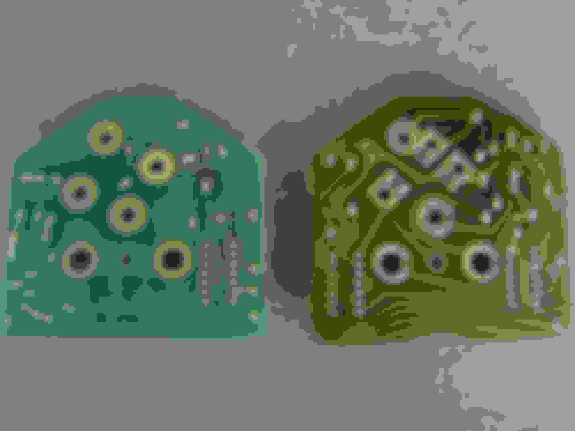
Technical study of original vs. replacement tach boards
For the tech curious, I've uploaded references for an original factory board (on the right) and a Wilcox replacement (left)...American made. We see some references on the Wilcox board using standard terms; ground, 12V, and coil with a reference on the bottom to RCI-F 94V0. Notice on the board the copper path beneath what appears as a green laminate, a protective measure. Early boards, the copper would crack, breaking continuity. On the front side note that potentiometer (right side of board, look for color code blue with a glue to secure the set screw). its used for the "modern-day" calibration method.
the original board shows a part number on the copper path side. If you look closely at the upper right corner you can see where copper has emerged past this laminate. Component side; note the DIP chip to the right side of the board. This was the mechanism to calibrate the board and required some tools, which I'm sure are no longer available. The DIP or Dual-in-line Package is a 14-pin black and used a chip-type fixed-resistor network and was re-calibrated through 1996. So C4s used them too.
As the video shows, the 3 washers are the key! I originally did not include the washers since my old original board did not have any washers. There are 6 screws, but 3 washers! You need to use the 3 on the screws that come out of the center of the tach. - when I did this, it worked! I wish the replacement came with that small detail since it is a difference of working or not! I guess its not that small of a detail! LOL