


Autometer Speedo hook-up w/ LT1
Thread Starter
Pro


Joined: Jun 2001
Posts: 708
Likes: 0
From: Florida
I'm having problems with an Autometer Speedo (Phantom series, 5889) that I have installed in my '95LT1 / 4L60e powered '76 Vette.
Here is an e-mail I just sent to Autometer, but being that it's now Friday night, I don't expect to get a response until at least Monday...maybe others can help?
>> I'm using your Phantom series Electronic Speedo (5889) in a vehicle utilizing a '95 LT1 engine / 4L60e transmission (automatic, 4-speed) w/ a '95 F-body (Camaro / Firebird) PCM...
Per the instructions provided, I spliced into the VSS circuit (coming FROM the VSS - circuit A32, yellow wire) and connected into "Sig", then from "Out" connected back into the VSS wire going TO the PCM. After calibration, this worked for a few miles, then the transmission started shifting improperly (wouldn't come out of 1st, wasn't in the correct gear even if shifted manually, etc.) I bypassed the speedometer and connected the spliced wires from the VSS back to the PCM, but that didn't resolve the shifting problem. I ended-up having to replace 2 shift solenoids in the transmission before things were back to normal. Not knowing if that solenoid incident was caused by a problem w/ the speedometer or just a coincidence that it happened shortly after hooking up the speedometer, I just tried the connections again and same thing...no shifting out of first. I immediately stopped to avoid further damage and bypassed the speedometer again (all is OK w/ the transmission), but would REALLY like to have the speedometer functional.
I also have a "VSS OUTPUT" signal (circuit B8, green/white wire, in the F-Body PCM) and I tried connecting that TO "Sig", but get no response from the speedometer.
Connecting to either "VSS" or "VSS OUTPUT," the speedometer correctly goes thru it's calibration process (goes to MAX when holding reset button while starting, then goes to MIDPOINT when pressed again to start the 2-mile drive, then to ZERO when pressed @ the completion of the 2-mile drive), then no further response is seen.
Is there something I'm not doing correctly here?
Hopefully I provided enough detail...PLEASE let me know if any additional information is needed.
Thanks for your assistance...have a GREAT weekend.<<
I know others have installed these into their C4's or LT1 powered C3's (VetteDan, I PM'ed you w/ same info)...any ideas???
Thanks!
Burning Brakes


Joined: Jan 2002
Posts: 1,228
Likes: 1
From: Dallas Texas
Originally Posted by DR'76
OK, I'll try over at thirdgen.org...
Thanks.
Thanks.
Race Director


Joined: Mar 1999
Posts: 12,597
Likes: 237
From: Bartlett Illinois
Originally Posted by ninetyfivevette
Let us know what you find... I am sure more than just a few would love to ditch their stock cluster for a suite of Autometer analog gauges. I know I would.
My buddy when is he swapped in a 4L60E into a 90 Corvette had this issue if I remember right. Also Autometer may sell such a converter.
As for Autometer gauges in a C4..
I know.. BAD Photoshop.. LOL


Safety Car

Joined: Dec 2002
Posts: 3,655
Likes: 24
From: Charleston SC
I would normaly think that the speedo was having a problem with the pps rate of the VSS but the fact you had it working to begin with proves it is fine. From what you are describing I would either suspect a bad reluctor ring or a bad Speedo. I would contact Auto meter and make sure you did not need a load resistor of some sort to feed the speedo as to not load down the VSS signal then I would ask them how you can check it.
Thread Starter
Pro
Joined: Jun 2001
Posts: 708
Likes: 0
From: Florida
Originally Posted by CFI-EFI
4L60E equipped C4s get their VSS signal from a wheel reluctor, not the trans.
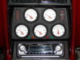
-=Jeff=- not bad w/ the Photoshop (better than I could do!), but AutoMeters look pretty cool in the C4 layout. I had to relocate my directionals, hi-beam and brake warning lamps as well...

I'm still waiting on a response from Autometer (I'm sure it will be after the weekend), BUT I did contact them PRIOR to purchasing and they said would be "fine"


Race Director

Joined: Sep 2000
Posts: 17,298
Likes: 33
From: The Top of Utah
Originally Posted by DR'76
CFI-EFI - wasn't sure what you meant by that. The 4L60e DOES have a VSS that is part of the transmission and feeds the info to the PCM thru circuit "A32" in the "RED" connector (See SM, page 7A-25, fig. 23).If you could further clarify..??? (Thanks!)
RACE ON!!!
Corvette Stories
The Best of Corvette for Corvette Enthusiasts

Top 10 Most Expensive Corvettes Ever Sold on Bring A Trailer
Brett Foote
10 Things Every Corvette Owner Needs (2026 Edition)
Michael S. Palmer
8 Most "Only Corvette Owners Understand" Quirks and Problems
Pouria Savadkouei
10 Reasons the C6 Z06 is Still A Performance Benchmark After 20 Years
Joe Kucinski
How Much Horsepower Every Corvette Engine "LOST" in 1972
Joe Kucinski
Top 10 DOs and DON'Ts for Protecting Your Convertible Top!
Michael S. Palmer
Top 10 Most Explosive Corvettes Ever Made: Power-to-Weight Ratio Ranked!
Joe Kucinski
150 hp to 1,250 hp: Every Corvette Generation Compared by the Specs That Matter
Joe Kucinski
8 Coolest Corvette Pace Cars (and Replicas) of All Time
Verdad Gallardo
Melting Slicks

Joined: Aug 1999
Posts: 2,240
Likes: 42
From: Baltimore, MD USA
Originally Posted by DR'76
Per the instructions provided, I spliced into the VSS circuit (coming FROM the VSS - circuit A32, yellow wire) and connected into "Sig", then from "Out" connected back into the VSS wire going TO the PCM.
Thread Starter
Pro
Joined: Jun 2001
Posts: 708
Likes: 0
From: Florida
Originally Posted by CFI-EFI
Are you sure that VSS is for speedo display and not for other ECM, PCM or other ??M functions?
(Sorry about the acronyms...they drive me nuts too
 )
)HOOKED: yeah I should have said "CUT", but see what you are saying...I should just tap/splice into ("T" into) the VSS signal, which should still provide a clean signal to the PCM and give a signal to the Speedo to work from. I don't think I tried that, but if so, will try it again...
Thanks for the replies... I'll post if that works or not and/or when Autometer replies w/ their suggestion.
Last edited by DR76; Feb 5, 2006 at 10:54 AM. Reason: typo
Thread Starter
Pro
Joined: Jun 2001
Posts: 708
Likes: 0
From: Florida
Either my soldering skills SUCK or the PCM is REALLY finicky about receiving a clean signal... I tried splicing (or "T"-ing) into the VSS wire to go into the "Sig" terminal of the Speedo and again, the tranny doesn't shift correctly.
I'm using "Silver-Bearing" solder (96% tin, 4% silver)...is there something better to use?
Thanks!
I'm using "Silver-Bearing" solder (96% tin, 4% silver)...is there something better to use?
Thanks!
Safety Car
Joined: Dec 2002
Posts: 3,655
Likes: 24
From: Charleston SC
Are you tapping into two wires or one off the tranny? looking at my Helms book it looks as if you have 2 wires for VSS off the tranny Yellow (VSS Ground or VSS Low depending on where it is refenced) and PPl (VSS Signal or VSS high). On the stock C4 it goes from the VSS and splits to the SRC (Selective Ride Controll) and the ECM. I would think thta would indicate that with proper impedance you should be able to tap a second source (Your gauges) without a problem. I don't know but somthing to think about is that the VSS ground may be a data return signal and may not like a chassis ground attached. So if you are only tapping one wire look at the Autometer directions and see if they have a signal called VSS return or somthing similar.
Melting Slicks
Joined: Aug 1999
Posts: 2,240
Likes: 42
From: Baltimore, MD USA
I was looking at this site http://www.customclassictrucks.com/howto/23679/
Their Autometer Speedometer has inputs for a sine wave or square wave signal.
If yours also has two inputs are you connecting the Yellow wire to the sine wave input?
The solder you used should be no problem.
Autometers web-site is useless.
Their Autometer Speedometer has inputs for a sine wave or square wave signal.
If yours also has two inputs are you connecting the Yellow wire to the sine wave input?
The solder you used should be no problem.
Autometers web-site is useless.
Last edited by Hooked on Vettes; Feb 5, 2006 at 06:48 PM.
Thread Starter
Pro
Joined: Jun 2001
Posts: 708
Likes: 0
From: Florida
Originally Posted by FD2BLK
Are you tapping into two wires or one off the tranny? looking at my Helms book it looks as if you have 2 wires for VSS off the tranny Yellow (VSS Ground or VSS Low depending on where it is refenced) and PPl (VSS Signal or VSS high).
Anyway, looking at the four (4) PCM Connector figures, "VSS" is referenced in 3 of the wire descriptions: Pin A31 (VSS Ground - circuit 401, purple), Pin A32 (VSS Signal - circuit 400, yellow) and B8 (VSS OUTPUT - circuit 817, dark green w/ white)
I first tried the VSS OUTPUT wire to the "Sig" terminal in back of the Speedo, but got no response from the speedo. Then I cut the VSS SIGNAL wire and connected that to "Sig", then from the "Out" terminal went back to the PCM (So the path went FROM the VSS on the tranny, TO the "Sig" of the speedo, then from the "Out" of the speedo back to the PCM) This got the speedo functioning for a while, then had tranny shifting problems. My latest test was to just "T" into the VSS SIGNAL wire and go to "Sig" on the Speedo (nothing connected to "Out"). This also caused tranny shifting problems.
Hooked: No, my Speedo just has the "Sig" terminal. The directions supplied w/ the speedo show that either SINE or SQUARE wave would connect to that terminal and also has this notation:
"NOTE: This speedometer provides an output (OUT) terminal that can be used with late model vehicle installations using the existing VSS. In these installations, the VSS signal wire should be connected to the SIG terminal of the speedometer only. The OUT terminal should be connected to where the VSS output was originally wired. This will provide a buffered VSS signal to the PCM/computer in the vehicle."
It seems so simple
Last edited by DR76; Feb 5, 2006 at 10:55 PM. Reason: clarification
Safety Car
Joined: Dec 2002
Posts: 3,655
Likes: 24
From: Charleston SC
Originally Posted by DR'76
FD2BLK:Which year Helms manual are you looking at? I don't see any "high" or "low" references in my '95 manual. (just for clarification, the Helms manual is the Service Manual, correct? I don't see "Helms" anywhere in my Service Manual, so want to be sure).
Anyway, looking at the four (4) PCM Connector figures, "VSS" is referenced in 3 of the wire descriptions: Pin A31 (VSS Ground - circuit 401, purple), Pin A32 (VSS Signal - circuit 400, yellow) and B8 (VSS OUTPUT - circuit 817, dark green w/ white)
Anyway, looking at the four (4) PCM Connector figures, "VSS" is referenced in 3 of the wire descriptions: Pin A31 (VSS Ground - circuit 401, purple), Pin A32 (VSS Signal - circuit 400, yellow) and B8 (VSS OUTPUT - circuit 817, dark green w/ white)
Safety Car
Joined: Dec 2002
Posts: 3,655
Likes: 24
From: Charleston SC
Originally Posted by DR'76
"[B
"[B
NOTE:[/B] This speedometer provides an output (OUT) terminal that can be used with late model vehicle installations using the existing VSS. In these installations, the VSS signal wire should be connected to the SIG terminal of the speedometer only. The OUT terminal should be connected to where the VSS output was originally wired. This will provide a buffered VSS signal to the PCM/computer in the vehicle."
It seems so simple
It seems so simple
This sounds as if you are not suposed to splice into it at all but rather cut it and connect the VSS side into the speedo and use the Out terminal and connect it to the ECM, is this how you have it connected? If you have it spliced it could be causing the load to the ECM I was refering to.
Somthing like this I would think would be the correct way
VSS------>(Speedo-->Out terminal)------>ECM
Rather then this
VSS-------->ECM and Speedo
Last edited by FD2BLK; Feb 5, 2006 at 11:16 PM.
Burning Brakes
Joined: Jan 2002
Posts: 1,228
Likes: 1
From: Dallas Texas
Originally Posted by Hooked on Vettes
Their Autometer Speedometer has inputs for a sine wave or square wave signal.
Last edited by ninetyfivevette; Feb 5, 2006 at 11:53 PM.
Thread Starter
Pro
Joined: Jun 2001
Posts: 708
Likes: 0
From: Florida
Originally Posted by FD2BLK
VSS------>(Speedo-->Out terminal)------>ECM
I think having a "hybrid" is going to make this more complicated than it should be BUT, I have a '76 Vette w/ only a '95 PCM, so I don't have any SRC, CCM, traction control, cruise control or any of the modern-day "options".
I now see where you referenced the "hi" and "low", but that's in the SRC (which I don't have) so not sure if that will come into play??? I do see on page 8A-33-3 (in the 95 book) where it discusses the fuctions of the VSS. It states that the VSS does produce a SINE wave (thank you "ninetyfive" for also pointing that out), THEN it gets amplified and converted to a SQUARE wave by the PCM which would then send this SQUARE wave out thru "B8" (or circuit 817) to such things as the SRC, Cruise Control Module, CCM, and Radio Control Head (all things I DON'T have). So (as you stated) it must go thru the CCM before getting to the speedometer, and don't know what happens to the signal inside the CCM...???
Maybe Autometer will reply and be able to make sense out of this...
Thanks to all for the replies...it's definitely been a learning experience!
OK, it's midnight here...MUST sleep!
Last edited by DR76; Feb 6, 2006 at 12:07 AM. Reason: clarify
Safety Car
Joined: Dec 2002
Posts: 3,655
Likes: 24
From: Charleston SC
You should not need any of the devices in a C4 so that won't be a problem, the F-body does not have CCM, radio head or even the SRC as far as I know. The only reason I even mentioned the SRC is the fact they do refer to the same signals by differnt names leading to the posibility of the ground not being a hard ground but mabey a signal return. I think you have done everything correct and in reading your post are on the right path. At this point you realy do need feedback from Auto meter. Good luck and keep us posted. 

Drifting

Joined: Feb 2002
Posts: 1,952
Likes: 2
From: Little Rock Arkansas
Well...I'm sorta doing the same thing... Just installed a LS1/4L60E into a '96 Caprice 9C1 (copcar); also installed a full Auto Meter guage cluster in place of the digi-dash. On the LS computers they have a 4k pulse coming off of the ECU to the speedo...I just connected that to the "Sig" on the speedo and left the "out" unplugged...Works perfectly. I should mention this IS an aftermarket wiring harness, though.
-Jeb
-Jeb