


LD85's Holley Stealth Ram

Thread Starter
Le Mans Master


Joined: Jan 2002
Posts: 9,036
Likes: 13
From: Edmonton AB
After clearing this with LD85, I am taking the liberty of creating a new
thread based on Holley Stealth Ram posts in his earlier thread.
Max overbore for a 406CI , 509 casting ?
JoBy's thread 'My HSR Modification' covers JoBy's work in superb depth
and there are plenty of contributions. LD85 is looking at a different
approach that is also interesting - to me, at any rate.
For my part, I'd encourage you to start a thread on
this aspect of the project, if you are inclined to share.
I'm sure I'm not alone in being interested.
.
I will take pics of the process, basically it will look like a reduced height
factory HSR plenum, saving the top ribs for appearance.
I plan on putting the plenum on a Bridgeport mill and using a vertical
collet type slitting saw to cut the bottom 1" (or what ever it takes, off
of the bottom off of the plenum all the way around, and will machine
the bolt hole support pillars flush with the bottom too.
Then I'll weld in a new piece of 5/16 or 3/8 thick 6061 aluminum in
place of the cast piece that I cut out, this piece will have all of the
intake and mounting holes machined into it beforehand.
Then I will take another block of aluminum, put the mounting holes in it
and either bolt or weld it to the front of the plenum for the necessary
throttle body down angle.
Then polish it up and bolt it on. I will still use the existing mounting
holes and wont have to grind anything off of the intake runners.
FWIW, I won't receive the HSR until Monday or Tuesday since I bought
it used from a guy in Texas and probably wont post pics for another
2-3 weeks.
My engine is due back at the mid to end of next week and I plan on
putting it back in before I start this mod and F1 weekend I will have
friends coming into town from Cali and FLA.
.
thread based on Holley Stealth Ram posts in his earlier thread.
Max overbore for a 406CI , 509 casting ?
JoBy's thread 'My HSR Modification' covers JoBy's work in superb depth
and there are plenty of contributions. LD85 is looking at a different
approach that is also interesting - to me, at any rate.
Originally Posted by LD85
Originally Posted by Slalom4me
Originally Posted by LD85
Gonna be topped off with a HSR, that will use the HSR plenum and it
will still be removable with the stock HSR bolts, and still fit under a C4
hood.
will still be removable with the stock HSR bolts, and still fit under a C4
hood.
this aspect of the project, if you are inclined to share.
I'm sure I'm not alone in being interested.
.
factory HSR plenum, saving the top ribs for appearance.
I plan on putting the plenum on a Bridgeport mill and using a vertical
collet type slitting saw to cut the bottom 1" (or what ever it takes, off
of the bottom off of the plenum all the way around, and will machine
the bolt hole support pillars flush with the bottom too.
Then I'll weld in a new piece of 5/16 or 3/8 thick 6061 aluminum in
place of the cast piece that I cut out, this piece will have all of the
intake and mounting holes machined into it beforehand.
Then I will take another block of aluminum, put the mounting holes in it
and either bolt or weld it to the front of the plenum for the necessary
throttle body down angle.
Then polish it up and bolt it on. I will still use the existing mounting
holes and wont have to grind anything off of the intake runners.
FWIW, I won't receive the HSR until Monday or Tuesday since I bought
it used from a guy in Texas and probably wont post pics for another
2-3 weeks.
My engine is due back at the mid to end of next week and I plan on
putting it back in before I start this mod and F1 weekend I will have
friends coming into town from Cali and FLA.
Thread Starter
Le Mans Master
Joined: Jan 2002
Posts: 9,036
Likes: 13
From: Edmonton AB
While your manifold is enroute, here are pictures and some
food for thought. I'm know you followed JoBy's great work
on this topic in 'My HSR modification'
The ribs on top consume 1/4" valuable clearance. They may
also provide necessary reinforcement. There are nine ribs.
The engine is offset, relative to the hood. Perhaps removing
3 ribs on the driver's side for clearance, plus three on the
passenger side for visual symmetry (which still leaves three
ribs along the middle for some support) might be an idea to
consider.
What about using a hole saw to cut around the perimeters
of the column bottoms? This would permit the existing
plenum bottom to be removed with a horizontal cut around the
sides, say 3/8" up from the bottom. Once the sides are
sectioned the desired amount, the original bottom could be
positioned back in place.
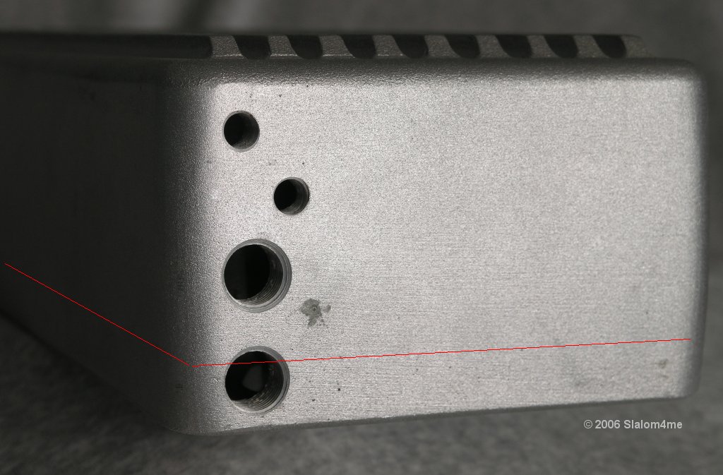
The front plate of the plenum is thin with cast bosses on the
back for thread support, some which are blind holes, IIRC.
Would it save time and difficulty to remove the entire front
side with a vertical cut, say 1/2" back from the machined face,
reposition the front side canted forward the desired amount
and then reattach it?
Keep in mind that the cable bracket needs to be mounted. There
is a pad on the driver's side of the plenum. Moving the TB
mount may mean the pad placement needs to be reviewed. Also,
the cable bracket needed modification IIRC on another installation
(JoBy's ??) - the front fuel rail boss on the lower manifold
comes up in that area. So step back and picture the interplay
of ALL the assembled components.
There is a port in the way at the back, but this is trivial.
The manifold above on the right does NOT exist, it is the
result of some liberties I took with JoBy's original image.
Notice how the plenum is relieved to provide clearance for
both front and rear fuel rail bosses. Also notice the forward
cant of the front of the plenum.
89_Paul_in_Cal and SloRVette have both mentioned significant
EGT variations with the HSR. Perhaps moreso with a low-profile
plenum. I've wondered whether the TB is too close to the front
runners and if the flow is being directed past the 1-2-3-4
runner cluster by the throttle plates. If there was room, it
would be interesting to push the TB forward like you are proposing.
SloRVette has installed a NO2 plate on the front of his plenum.
With the pleunum lowered and the throttle body tipped forward,
the IAC, linkage and other stuff on the TB need clearance around
the thermostat and the fuel rail cross-over tube. I wonder whether
the fuel rails could be modified so that the cross-over mounts in
between the runner clusters, instead of up front if this helps provide
more clearance.
The runners may offer some opportunities for a simple flycut.
But notice how they begin to curve outward prominently about
5/16" down? Does it matter if the runners wind up being further
apart from each other as a result of a milling cut? The bolt
holes are blind - if they need to be extended they will intrude
into the runners.
food for thought. I'm know you followed JoBy's great work
on this topic in 'My HSR modification'
The ribs on top consume 1/4" valuable clearance. They may
also provide necessary reinforcement. There are nine ribs.
The engine is offset, relative to the hood. Perhaps removing
3 ribs on the driver's side for clearance, plus three on the
passenger side for visual symmetry (which still leaves three
ribs along the middle for some support) might be an idea to
consider.
What about using a hole saw to cut around the perimeters
of the column bottoms? This would permit the existing
plenum bottom to be removed with a horizontal cut around the
sides, say 3/8" up from the bottom. Once the sides are
sectioned the desired amount, the original bottom could be
positioned back in place.
The front plate of the plenum is thin with cast bosses on the
back for thread support, some which are blind holes, IIRC.
Would it save time and difficulty to remove the entire front
side with a vertical cut, say 1/2" back from the machined face,
reposition the front side canted forward the desired amount
and then reattach it?
Keep in mind that the cable bracket needs to be mounted. There
is a pad on the driver's side of the plenum. Moving the TB
mount may mean the pad placement needs to be reviewed. Also,
the cable bracket needed modification IIRC on another installation
(JoBy's ??) - the front fuel rail boss on the lower manifold
comes up in that area. So step back and picture the interplay
of ALL the assembled components.
There is a port in the way at the back, but this is trivial.
The manifold above on the right does NOT exist, it is the
result of some liberties I took with JoBy's original image.
Notice how the plenum is relieved to provide clearance for
both front and rear fuel rail bosses. Also notice the forward
cant of the front of the plenum.
89_Paul_in_Cal and SloRVette have both mentioned significant
EGT variations with the HSR. Perhaps moreso with a low-profile
plenum. I've wondered whether the TB is too close to the front
runners and if the flow is being directed past the 1-2-3-4
runner cluster by the throttle plates. If there was room, it
would be interesting to push the TB forward like you are proposing.
SloRVette has installed a NO2 plate on the front of his plenum.
With the pleunum lowered and the throttle body tipped forward,
the IAC, linkage and other stuff on the TB need clearance around
the thermostat and the fuel rail cross-over tube. I wonder whether
the fuel rails could be modified so that the cross-over mounts in
between the runner clusters, instead of up front if this helps provide
more clearance.
The runners may offer some opportunities for a simple flycut.
But notice how they begin to curve outward prominently about
5/16" down? Does it matter if the runners wind up being further
apart from each other as a result of a milling cut? The bolt
holes are blind - if they need to be extended they will intrude
into the runners.
Race Director


Joined: Feb 1999
Posts: 12,772
Likes: 17
From: Indianapolis IN
Yeah, I was aware that the rear vacuum / pipe tap hole would be cut into, and I had planned on just using an end mill and plunging into the offset hole so that I could re-center that hole out and make a new fresh hole that I could re-tap.
On cutting the Throttle Body face off, I had thought about the possibility of cutting the parallel 1" line up to the front and then going vertical so I could take the TB/mount plate off, but I think that a new block might be just as easy and it would allow for more threads to be tapped into the block.
When I cut the bottom off, I will probably machine the 1" lip that will be attached to the bottom piece off ,,,,, and machine it dfown flat so that the bottom is just a flat piece, then I might re-weld it to the bottom so don't have to make another bottom.
Another thought I had was to cut the top off so it is a flat piece, then weld a 3/8" square piece of aluminum to the ID of the Plenum at the top juts under the top lip, so that it makes a removable lid for removing the top from the plenum while leaving the plenum base onto the runners. I dont like it becusue it would take several holes and gasketing etc.
All in all, my goal is to make this as cut and dried as possible while attempting to salvage the cosmetics as much as possible. By machining the ribs off the top, you would add more volume to the plenum by not having to machine as much from the base. By addign a block to the TB mount plate, I can add a little volume and lengthen it to clear the thermo housing.
I am open to suggestions for sure, but I have thought about this incessantly while driving in my car for 10-12 hours daily and it is starting to make me crazy-er.
Race Director
Joined: Feb 1999
Posts: 12,772
Likes: 17
From: Indianapolis IN
Been looking at the back of the TB blades and I do think they are too close to the front 1,2,3,4 tunnel stack, I will look into seeing how far forward I can push the TB,,,,,, when I put my TB mount plate on, I can move this forward.
Also, I am considering adding a curved panel inside the rear of the plenum to direct the air downward off of the roof of the plenum and into the 5,6,7,8 stack
Going on vacation this Friday but by 1-week from Friday, I should be wacking on the mill.

Also, I am considering adding a curved panel inside the rear of the plenum to direct the air downward off of the roof of the plenum and into the 5,6,7,8 stack
Going on vacation this Friday but by 1-week from Friday, I should be wacking on the mill.
Thread Starter
Le Mans Master
Joined: Jan 2002
Posts: 9,036
Likes: 13
From: Edmonton AB
Originally Posted by LD85
Also, I am considering adding a curved panel inside the rear of the plenum
to direct the air downward off of the roof of the plenum and into the
5,6,7,8 stack
to direct the air downward off of the roof of the plenum and into the
5,6,7,8 stack
radius on the top of the runners if these rise through the floor of the
plenum. Or build something into the plenum that extends the clusters
up off the floor and provides a bell-mouthed transition into the runners.
A couple of examples appeared in JoBy's thread


.
Thread Starter
Le Mans Master
Joined: Jan 2002
Posts: 9,036
Likes: 13
From: Edmonton AB
I need to add that my thinking has always been about how
to retain as much runner length as possible. So in part, this
is where the focus on extending the runners into the plenum
is coming from.
Of course, there is a benefit to airflow from the velocity
stack approach, relative to just having a sharp transition
from a flat floor into the runners.
Your needs and ideas may differ.
.
Race Director
Joined: Feb 1999
Posts: 12,772
Likes: 17
From: Indianapolis IN
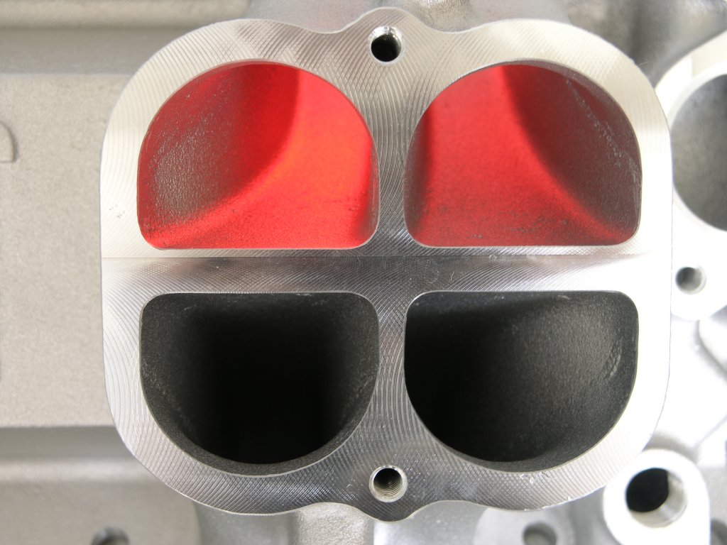
I could match the profile of the 4 hole stack with an aluminum riser (2X) and weld them to the floor (ID),
and then machine around the perimiter of the stack with a radius cutter and this could create efectively the same type of bell mouth that you speak of, except it would only be a 180 degree lip instead of a 270-degree lip.
If the floor to ceiling height is @ 2.50, and I could add lets say 1.00",,, my fear would be that I may be reducing too much of the plenum volume for air supply.
Corvette Stories
The Best of Corvette for Corvette Enthusiasts

Top 10 Most Expensive Corvettes Ever Sold on Bring A Trailer
Brett Foote
10 Things Every Corvette Owner Needs (2026 Edition)
Michael S. Palmer
8 Most "Only Corvette Owners Understand" Quirks and Problems
Pouria Savadkouei
10 Reasons the C6 Z06 is Still A Performance Benchmark After 20 Years
Joe Kucinski
How Much Horsepower Every Corvette Engine "LOST" in 1972
Joe Kucinski
Top 10 DOs and DON'Ts for Protecting Your Convertible Top!
Michael S. Palmer
Top 10 Most Explosive Corvettes Ever Made: Power-to-Weight Ratio Ranked!
Joe Kucinski
150 hp to 1,250 hp: Every Corvette Generation Compared by the Specs That Matter
Joe Kucinski
8 Coolest Corvette Pace Cars (and Replicas) of All Time
Verdad GallardoRace Director
Joined: Feb 1999
Posts: 12,772
Likes: 17
From: Indianapolis IN
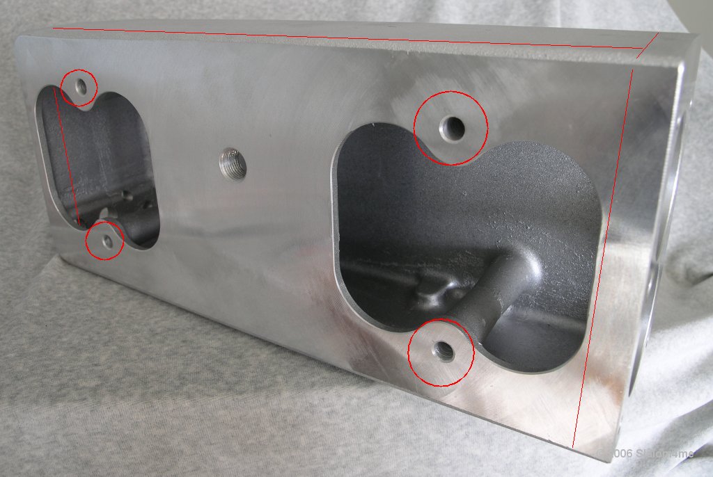
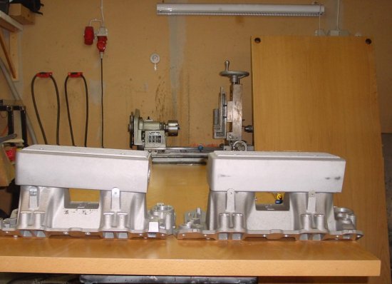
OK, I did some work today, I trimmed the plenum height and machined the base to fit inside the ID of the Plenum side walls.
I also machined off all of the ribs and re-machined .250" wide by .060" deep slots in the plenum so there will still be the opportunity to fill the grooves with some paint to make it "purdy",,, you can tell much by this pic, but i will sand it all down when it is finished.
I did mess up by machining the relief in the base for the throttle bracket boss, I marked it wrong and made it too big, but not to worry, Ol'RJ will solve this, because he IS a master welder
For the welding, RJ will weld along the base and Plenum sidewalls so this should not be visible after he is done also, I made the holes for the bolt columns .060" shorter than the overall legnth of the Plenum sidewalls so RJ can fill in the large holes with weld and then I will put a clearance drill back thru his welds and fly cut the base, if necessary #@ .030" .
Last edited by LD85; Jul 22, 2006 at 03:16 PM.


Race Director
Joined: Feb 1999
Posts: 12,772
Likes: 17
From: Indianapolis IN
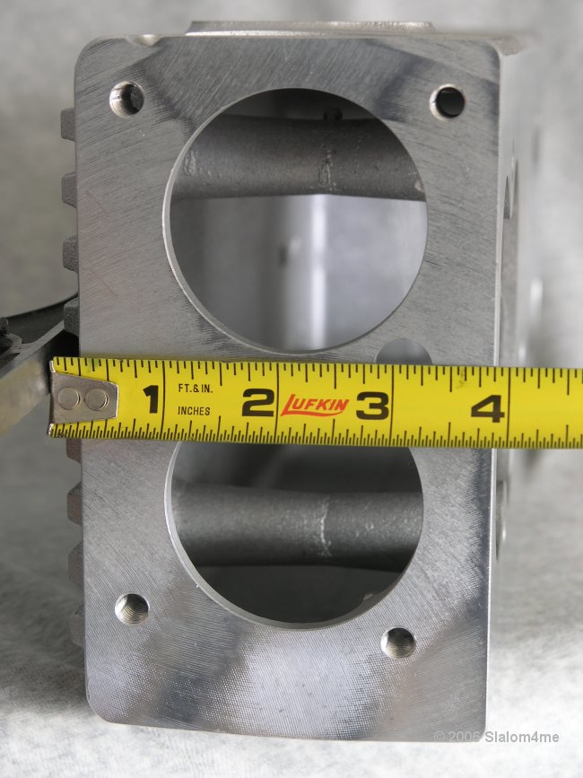
Finished overall height with NO RIBS = 2.900"
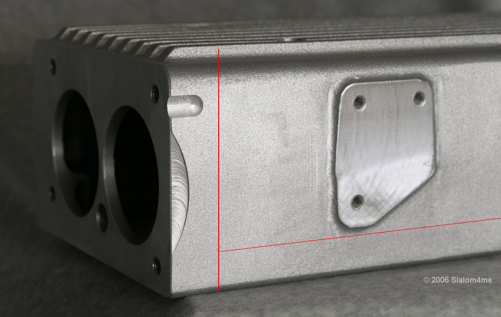
Next I will weld a 3.50" tall by 2.0" tick by 6.50" wide block of 6061 aluminum to the front to mount the TB too and then clean it up.
It will be cut on an angle (@30 degrees?) so as to tilt the front of the TB downward. I will machine out the TB bore holes in the aluminum block as much as possible and this will add some volume back to the plenum. In reality, I only lost .760" of height since the cosmetic top FINS accounted for .250 of the necessary clearance. The walls are .200 thick so I dont think they are there for support.
I am still waiting on my HSR intake to come back from powder coat,
In reality, I would have been better off making a new one out of aluminum sheet and shearing and breaking it up to be 4 pieces wtih a mount plate on the front,,,, and this may still happen this winter.
Last edited by LD85; Jul 26, 2006 at 09:54 PM.
Team Owner

Joined: Jun 2002
Posts: 21,510
Likes: 0
From: On a Wisconsin Death Trip
Originally Posted by Caboboy
This is gonna be a great thread! L98 guys need an alternative in the worst way

Why Holley would make an intake that would not fit a good percentage of TPI cars (Corvettes) is beyond me.
Well, I know why - it's probably because it was never intended as a TPI replacement intake but as a stand alone EFI deal, but still, it's frustrating.
Le Mans Master


Joined: Jul 2001
Posts: 8,183
Likes: 3
From: Santa Maria, CA
In reality, I would have been better off making a new one out of aluminum sheet and shearing and breaking it up to be 4 pieces wtih a mount plate on the front,,,, and this may still happen this winter.
I took a TIG welding class at the local community college and as it turns out, the instructor is one of the welders there at Hogan's.
I did try to get the dime tour of Hogan's courtesy of my instructor, but the owner keeps the place like a fort knox.
I wanted to see how they do them in the hopes of doing one on my own and sharing the data with you guys. Their flow data and designs are well gaurded and from what I was told not even the welders themselves know the info. They just put 'em together and weld 'em as instructed.
I picked up a nice lincoln squarewave recently and will begin tigging things pretty soon here. I just might make the intake anyways. ???
Race Director
Joined: Feb 1999
Posts: 12,772
Likes: 17
From: Indianapolis IN
Originally Posted by 89 Paul in Cal
Hogan's manifolds makes these all the time, but as we all know around $3,500.00.
I took a TIG welding class at the local community college and as it turns out, the instructor is one of the welders there at Hogan's.
I did try to get the dime tour of Hogan's courtesy of my instructor, but the owner keeps the place like a fort knox.
I wanted to see how they do them in the hopes of doing one on my own and sharing the data with you guys. Their flow data and designs are well guarded and from what I was told not even the welders themselves know the info. They just put 'em together and weld 'em as instructed.
I picked up a nice Lincoln squarewave recently and will begin tigging things pretty soon here. I just might make the intake anyways. ???
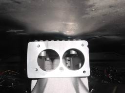
The problem as I see it with the HSR, is that the runner design takes up most of your available work height. And really to do this and make the runners 2" longer, and also make the trumpet openings,,,,,,, there is just not enough room. There is only a max of 2.900" vertical inches to work with so you have to make the Plenum longer and wider to match the volume of the HSR off the shelf. I figured out that I lost 25% of the plenum volume as the plenum sets in the picture. Adding the Throttle Body block to the front will gain a little more,
But in reading on the web about Intake Plenum Volume, you read that no body has a cold fast formula, and that there are many variables. This current effort as seen above is really just trying to use the factory plenum and see what happens. In a perfect world, I would have made the plenum wider and slightly longer at the rear, and would have used round corners. I will lay the next one out in Auto/CAD and machine one to print, instead of "winging it" like I am doing on this one.
They make a lot of extruded aluminum shapes nowadays to work with.
Race Director
Joined: Feb 1999
Posts: 12,772
Likes: 17
From: Indianapolis IN
I should have the HSR base by Friday, it is done,, Silver Powder Coat with Clear on top..I will machine the TB mount block Saturday or Monday, then have it welded on by mid next week. So sometime next week this should be wrapped up,
Oh yeah, it is welded to fit a 1206 Felpro.

Oh yeah, it is welded to fit a 1206 Felpro.
Last edited by LD85; Jul 26, 2006 at 04:39 PM.


Race Director
Joined: Feb 1999
Posts: 12,772
Likes: 17
From: Indianapolis IN
Originally Posted by Slalom4me
Was a definitive answer ever determined with regard to the
reports back in 2003 of vacuum leaks when using the Stealth Ram
with certain head/port configurations? .
reports back in 2003 of vacuum leaks when using the Stealth Ram
with certain head/port configurations? .
Race Director
Joined: Feb 1999
Posts: 12,772
Likes: 17
From: Indianapolis IN
OK,,, I'm making slow progress, I need to have the plenum welded to the TB block and I need to polish up and the TB block inside.
I milled 5-degrees off the front of the plneum, then another 5-degrees off teh block for a total of 10-degrees off of vertical ,,, I need @ another 30 minutes on the Bridgeport to smooth the ID of the TB block out so there is max volume in the ID of the block, the flow is unobstructed, or it will be.
Everything clears and works except the Thermo-housing, but until the Plenum is welded and everything is in a fixed position, I cant hatch a plan yet.
Monday I can bolt it on after Master Welder Ol'RJ lays some rod on it. Umm, welding rod that is.
Last edited by LD85; Jul 29, 2006 at 10:32 PM.

