


Dealing With Cam Overlap
Thread Starter
Burning Brakes


Joined: Nov 2001
Posts: 1,241
Likes: 9
From: Houston TX

i didn't accurately explain the symtpoms. in hindsight, i think i made the mistake of using the term "tip in," when the issue was really related to throttle angle. i could hold this slight throttle angle and the engine would continue to misbehave until i either let off or fed it more.
the TPS base setting did indeed change this. i guess the '94-'95 ecm doesn't accurately baseline the TPS below a certain threshold. with the closed TPS voltage at 0.88V, it now instantly shows open throttle in datalogs as soon as i touch the throttle.
that said, i tried something today, mostly for fun. i forced the ecm to stay in open loop all the time. fueling appears to be based on load (MAP) and MAF flow. it drives unbelievably well, better than the stock engine did with a HOT cam. i'm tempted to stay like this.
also, with just the MAF determining fueling, the wideband shows 15.5:1 to 16:1 a/f at idle. it sometimes seems like it's on the verge of trying to surge a bit, but then it corrects itself.
i'll drive it some more like this and try some wot wideband runs, then report back.
-michael
the TPS base setting did indeed change this. i guess the '94-'95 ecm doesn't accurately baseline the TPS below a certain threshold. with the closed TPS voltage at 0.88V, it now instantly shows open throttle in datalogs as soon as i touch the throttle.
that said, i tried something today, mostly for fun. i forced the ecm to stay in open loop all the time. fueling appears to be based on load (MAP) and MAF flow. it drives unbelievably well, better than the stock engine did with a HOT cam. i'm tempted to stay like this.
also, with just the MAF determining fueling, the wideband shows 15.5:1 to 16:1 a/f at idle. it sometimes seems like it's on the verge of trying to surge a bit, but then it corrects itself.
i'll drive it some more like this and try some wot wideband runs, then report back.
-michael
Thread Starter
Burning Brakes
Joined: Nov 2001
Posts: 1,241
Likes: 9
From: Houston TX
FWIW:
2. Re the TPS reading - dunno why you are seeing that. Is there a different scale in your data recording
prog to look at TPS volts (or A/D counts) directly, instead of TPS %? Are you using an aftermarket
TB? In engineering terms, you're probably aware that gas-flow vs position is VERY non-linear for butterfly
valves, with very large outputs for very small changes at the low end, trailing off more or less to an
asymptote once you reach ~75-80% open on the blade. A large-bore TB only amplifies that transfer
function - having way more opening than you need for flow modulation.
2. Re the TPS reading - dunno why you are seeing that. Is there a different scale in your data recording
prog to look at TPS volts (or A/D counts) directly, instead of TPS %? Are you using an aftermarket
TB? In engineering terms, you're probably aware that gas-flow vs position is VERY non-linear for butterfly
valves, with very large outputs for very small changes at the low end, trailing off more or less to an
asymptote once you reach ~75-80% open on the blade. A large-bore TB only amplifies that transfer
function - having way more opening than you need for flow modulation.
btw, this is the oem TB. i had a 52mm bored one i tried on the dyno and gained 0hp, so went back to a stock one. the wideband does actually lag a bit when i whack the throttle open, but i can't tell if it's really momentarily lean or if the sensor just isn't responding quickly enough. i can't tell anything is wrong in the tune from how it responds to big throttle inputs, and no detonation. all the problems were related only to very small throttle inputs.
but, today i had the opportunity to air out longer than usual, and the ecm tripped a TPS V too high code. so fixing the transition from idle to cruise caused the TPS V with TB fully open to exceed limits. i can't find where to change the upper limit, only to turn the code off.
is it acceptable to just turn the code off? or does the high TPS V affect engine management?
BTW, on the LT1 tunes I've looked at, most wanted to use a lot of IAC opening. That put air into the
idle circuit holes in the manifold, correcting what looked like big air-flow maldistribution in the base
intake shape at lower RPMs. Quite a bit was written some years ago on machining aftermarket TBs
to fit the LT1 idle air circuit...
idle circuit holes in the manifold, correcting what looked like big air-flow maldistribution in the base
intake shape at lower RPMs. Quite a bit was written some years ago on machining aftermarket TBs
to fit the LT1 idle air circuit...
right now my ecm will vary each bank (independently) quite a lot at idle, slowly rolling through 2.5ms to 4.5ms. sometimes the banks match, most of the time they're different. both sensors are new, maybe the exhaust pressure or temps are varying a lot, because they will show readings that look completely wrong. more load/rpm shows things that look more correct, and when in forced open loop the wideband shows a very steady and tight afr range.
any bump in the power curve. On mine, the change from closed-TPS to main-table is governed by
both RPM and VSS - so I have the transition set for ~5 mph. Works for me, anyway...
both RPM and VSS - so I have the transition set for ~5 mph. Works for me, anyway...
thanks.
-michael

Burning Brakes
Joined: May 1999
Posts: 760
Likes: 1
From: Greenwich, CT
Hmmm-
1. Re TPS - I've owned a bunch of GM cars over the years and haven't had a problem with a TPS
ever, so I can only speculate about things you probably already know:
On mine, IIRC the MAP and TPS share a regulated ~5v source and an ECM ground wire (check your
wire diagram to confirm your own box). Note the ECM ground does NOT have to be at the same
potential as the chassis ground. The TPS is just a voltage divider, returning a v signal to the PCM.
Noting your difficulty near the bottom of the scale, I'd start looking for a bad potentiometer or
dirty connector, or possibly a bad source v from the PCM.
If other devices share the same source and ground wires, it's also possible something else on those
lines is goofing up your TPS signal - in my case I'd check my MAP unit for shorts or something weird.
I'm inclined to find the source of a problem rather than just silence the Trouble Code, but that's just
me. The TPS hi alarm must be related to the low problem as well... at this point it doesn't sound
mechanical, but I'd check the throttle arm for free travel, anyway.
2. Lingenfelter mentions LT1 air distribution problems (briefly) in his engine book, and a lot of folks
report split BLMs at low engine speed. The only guy I know of to SOLVE the problem did it by building
an external air-tubing network that he then connected to each runner:
http://www.thirdgen.org/techboard/at...m-split-under-
Write-up here: http://www.thirdgen.org/techboard/di...ram-split.html
Dunno if it does any good, but it really is clever .
.
3. On my ECM the two permissives to transition from the idle-spark table to the main-spark table are
both on the Tuner Cat 'ECM Constants' screen - i.e. RPM and VSS enable minima. IIRC they formed an
either/or logic gate. If you don't see them on your mask, drop a note to TC and ask him if they are
defined for $EE.
BTW, the best thing I did for rear-end 'twitch' was to install those DRM camber brackets - world of
difference on uneven pavement.
Running open-loop sounds promising for your car. I just had my mask open last week, to get this car
past smog inspection again - but I managed it in closed loop. Re the WB readings at tip-in, note that
the commercial WB units I've seen only displayed ~10 or so samples per second. That's the reason
I use a separate DATAQ a/d converter for my rig. It's picking up 120 samples/sec, which makes it
able to log short-duration bumps in the AFR - using it I can also see ignition misfires, weak injectors,
and whatnot.... it's not a digital O-scope, but for $25 I can leave it hooked up in the car all the time.
It (and the Honda WB sensor) are still running after 6 years of ~daily use.
Good luck with the project,
DrJ
1. Re TPS - I've owned a bunch of GM cars over the years and haven't had a problem with a TPS
ever, so I can only speculate about things you probably already know:
On mine, IIRC the MAP and TPS share a regulated ~5v source and an ECM ground wire (check your
wire diagram to confirm your own box). Note the ECM ground does NOT have to be at the same
potential as the chassis ground. The TPS is just a voltage divider, returning a v signal to the PCM.
Noting your difficulty near the bottom of the scale, I'd start looking for a bad potentiometer or
dirty connector, or possibly a bad source v from the PCM.
If other devices share the same source and ground wires, it's also possible something else on those
lines is goofing up your TPS signal - in my case I'd check my MAP unit for shorts or something weird.
I'm inclined to find the source of a problem rather than just silence the Trouble Code, but that's just
me. The TPS hi alarm must be related to the low problem as well... at this point it doesn't sound
mechanical, but I'd check the throttle arm for free travel, anyway.
2. Lingenfelter mentions LT1 air distribution problems (briefly) in his engine book, and a lot of folks
report split BLMs at low engine speed. The only guy I know of to SOLVE the problem did it by building
an external air-tubing network that he then connected to each runner:
http://www.thirdgen.org/techboard/at...m-split-under-
Write-up here: http://www.thirdgen.org/techboard/di...ram-split.html
Dunno if it does any good, but it really is clever
.3. On my ECM the two permissives to transition from the idle-spark table to the main-spark table are
both on the Tuner Cat 'ECM Constants' screen - i.e. RPM and VSS enable minima. IIRC they formed an
either/or logic gate. If you don't see them on your mask, drop a note to TC and ask him if they are
defined for $EE.
BTW, the best thing I did for rear-end 'twitch' was to install those DRM camber brackets - world of
difference on uneven pavement.
Running open-loop sounds promising for your car. I just had my mask open last week, to get this car
past smog inspection again - but I managed it in closed loop. Re the WB readings at tip-in, note that
the commercial WB units I've seen only displayed ~10 or so samples per second. That's the reason
I use a separate DATAQ a/d converter for my rig. It's picking up 120 samples/sec, which makes it
able to log short-duration bumps in the AFR - using it I can also see ignition misfires, weak injectors,
and whatnot.... it's not a digital O-scope, but for $25 I can leave it hooked up in the car all the time.
It (and the Honda WB sensor) are still running after 6 years of ~daily use.
Good luck with the project,
DrJ

Le Mans Master


Joined: May 2005
Posts: 5,214
Likes: 65
From: Queensland, AUSTRALIA
the combination of longtubes, slightly different O2 sensor locations, and the overlap definitely makes for some funky corrections in closed loop idle. i can really see how much worse this could be without the idle air distribution offered by the oem passages, yes.
right now my ecm will vary each bank (independently) quite a lot at idle, slowly rolling through 2.5ms to 4.5ms. sometimes the banks match, most of the time they're different. both sensors are new, maybe the exhaust pressure or temps are varying a lot, because they will show readings that look completely wrong. more load/rpm shows things that look more correct, and when in forced open loop the wideband shows a very steady and tight afr range.
right now my ecm will vary each bank (independently) quite a lot at idle, slowly rolling through 2.5ms to 4.5ms. sometimes the banks match, most of the time they're different. both sensors are new, maybe the exhaust pressure or temps are varying a lot, because they will show readings that look completely wrong. more load/rpm shows things that look more correct, and when in forced open loop the wideband shows a very steady and tight afr range.
2. Lingenfelter mentions LT1 air distribution problems (briefly) in his engine book, and a lot of folks
report split BLMs at low engine speed. The only guy I know of to SOLVE the problem did it by building
an external air-tubing network that he then connected to each runner:
http://www.thirdgen.org/techboard/at...m-split-under-
Write-up here: http://www.thirdgen.org/techboard/di...ram-split.html
Dunno if it does any good, but it really is clever
report split BLMs at low engine speed. The only guy I know of to SOLVE the problem did it by building
an external air-tubing network that he then connected to each runner:
http://www.thirdgen.org/techboard/at...m-split-under-
Write-up here: http://www.thirdgen.org/techboard/di...ram-split.html
Dunno if it does any good, but it really is clever
Just at a guess, is it richer on the left bank and leaner on the right at idle??
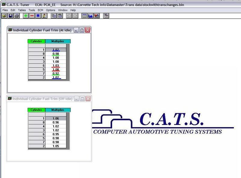
Here is the 2 tables, one for idle, one for off idle. There is a setting in Constants that will dictate at what TPS% it stops using the off idle table and goes to even delivery for all 8 cylinders, factory setting is 12.9%.
Last edited by Casethecorvetteman; Sep 5, 2007 at 07:58 AM.
Thread Starter
Burning Brakes
Joined: Nov 2001
Posts: 1,241
Likes: 9
From: Houston TX
i've thought about plumbing 8 EGT probes into the headers in order to get the cylinder balance really close, but that would be difficult and expensive considering how much power it makes already.
-michael
Le Mans Master
Joined: May 2005
Posts: 5,214
Likes: 65
From: Queensland, AUSTRALIA
Those are not my settings, they are stock settings. If you look at the coloured lines ive put on there, youll see opposing cylinders are equal at idle except 5 and 6 as well as 7 and 8. That is why i am taking a guess that your split BLM has the higher number on the right bank.
Right now youve got a split BLM at idle, and i can apreciate the fact that youre right about the guessing what to change, but if youre running from the stock settings on those 2 tables, they simply wont be right. Might as well start experimenting with it abit, cause i smoothed my idle out alot by doing that.
Right now youve got a split BLM at idle, and i can apreciate the fact that youre right about the guessing what to change, but if youre running from the stock settings on those 2 tables, they simply wont be right. Might as well start experimenting with it abit, cause i smoothed my idle out alot by doing that.

Le Mans Master

Joined: Feb 1999
Posts: 9,922
Likes: 38
From: South Carolina
St. Jude Donor '03 & '05

The rich/lean threshold vs airflow table (or similar, if available) should be suitable for tuning in the presence of excess air for certain flow conditions.
The PE vs rpm discussion was a different conversation regarding L98s with a 165 ecm as to whether or not PE vs rpm enrichment was still avalailable in open loop. It is. The mixture, however is not directly compensated by O2 feedback during PE in either closed loop or open loop, since the BLMS are prevented from being updated since they would be chasing a likely richer than stoichiometric target which wouldn't make sense with a narrow band O2.
Historic BLM values still offer mixture compensation even during PE, but they are not being updated in real time while in PE or open loop. This compensation can occur both in open and closed loop if non 128 blm values are stored.
GM/sec lower/upper Mv
0 579/ 597
32 522/ 557
64 548/548
96 513/513
128 495/495
I am researching split BLMs at idle and this thread is good help.
I run the AS&M 58mm T Body, drilled 11/64 drill bit through idle hole and epoxied in the back to seal airway passage for idle.
Corvette Stories
The Best of Corvette for Corvette Enthusiasts

How Much Horsepower Every Corvette Engine "LOST" in 1972
Joe Kucinski
Top 10 DOs and DON'Ts for Protecting Your Convertible Top!
Michael S. Palmer
Top 10 Most Explosive Corvettes Ever Made: Power-to-Weight Ratio Ranked!
Joe Kucinski
150 hp to 1,250 hp: Every Corvette Generation Compared by the Specs That Matter
Joe Kucinski
8 Coolest Corvette Pace Cars (and Replicas) of All Time
Verdad Gallardo
Top 10 Corvette Engines RANKED by Peak Torque (70+ Years of Muscle!)
Joe Kucinski
Corvette ZR1X Will Be Pacing the Indy 500, And Could Probably Race, Too!
Verdad Gallardo
Top 10 Corvettes Coming to Mecum Indy 2026!
Brett Foote
Top 10 C9 Corvette MUST-HAVES to Fix These C8 Generation Flaws!
Michael S. Palmer
Le Mans Master
Joined: Feb 1999
Posts: 9,922
Likes: 38
From: South Carolina
St. Jude Donor '03 & '05
The rich/lean threshold vs airflow table (or similar, if available) should be suitable for tuning in the presence of excess air for certain flow conditions.
The PE vs rpm discussion was a different conversation regarding L98s with a 165 ecm as to whether or not PE vs rpm enrichment was still avalailable in open loop. It is. The mixture, however is not directly compensated by O2 feedback during PE in either closed loop or open loop, since the BLMS are prevented from being updated since they would be chasing a likely richer than stoichiometric target which wouldn't make sense with a narrow band O2.
Historic BLM values still offer mixture compensation even during PE, but they are not being updated in real time while in PE or open loop. This compensation can occur both in open and closed loop if non 128 blm values are stored.
GM/sec lower/upper Mv
0 579/ 597
32 522/ 557
64 548/548
96 513/513
128 495/495
I am researching split BLMs at idle and this thread is good help.
I run the AS&M 58mm T Body, drilled 11/64 drill bit through idle hole and epoxied in the back to seal airway passage for idle.

Le Mans Master
Joined: Feb 2005
Posts: 5,146
Likes: 3
From: The Motor City
If it has a somewhat radical cam, the problem is that the excess overlap has an effect on O2 sensor readings because the O2 sensor was designed to read the results of combustion and now it is reading the results of combustion along with fresh oxygen that is being pulled through due to the overlap.
This means that even if you are at 14.7:1 at idle, the O2 sensor is going to see something leaner (even with a wideband). The INT. will raise and fuel will be added until the O2 sensor registers 14.7:1, the real AFR will be less than 14.7:1. AFR is related to the BPW, BPW=GMS of Air/(AFR, Injector Flow).
Changing the stoichiometric AFR will initially change the BPW. Decreasing the AFR will result in an initially higher BPW. This BPW then will soon change back to the normal BPW you previously had. The stoichiometric AFR does not control the BLMs., it controls the BPW. The O2 voltage points control the INT. It's when the INT swings a particular amount that the BLM then changes. It all comes down to is the O2 voltage points. Decrease the AFR and the initial BPW will increase. The O2 voltage swings will increase too. The INT is based off of predefined O2 mV swing points (constants), then the INT will decrease in order to stay in line with those O2 constants, the BLM will decrease and the BPW will return to normal even though a lower AFR.
In short, decrease the AFR and the initial BPW will increase. The O2 voltage swings will increase too. Since the INT is based off of predefined O2 mV swing points (constants), then the INT will decrease in order to stay in line with those O2 constants. The BLM will decrease and the BPW will return to normal even though you specified a lower AFR
Changing the stoichiometric AFR will initially change the BPW. Decreasing the AFR will result in an initially higher BPW. This BPW then will soon change back to the normal BPW you previously had. The stoichiometric AFR does not control the BLMs., it controls the BPW. The O2 voltage points control the INT. It's when the INT swings a particular amount that the BLM then changes. It all comes down to is the O2 voltage points. Decrease the AFR and the initial BPW will increase. The O2 voltage swings will increase too. The INT is based off of predefined O2 mV swing points (constants), then the INT will decrease in order to stay in line with those O2 constants, the BLM will decrease and the BPW will return to normal even though a lower AFR.
In short, decrease the AFR and the initial BPW will increase. The O2 voltage swings will increase too. Since the INT is based off of predefined O2 mV swing points (constants), then the INT will decrease in order to stay in line with those O2 constants. The BLM will decrease and the BPW will return to normal even though you specified a lower AFR
Last edited by mseven; Nov 5, 2007 at 01:08 PM.

Le Mans Master
Joined: Sep 2000
Posts: 6,303
Likes: 714
From: Bartlett IL
What voltages would be good to go down to. And my scales are different.
GM/sec lower/upper Mv
0 579/ 597
32 522/ 557
64 548/548
96 513/513
128 495/495
I am researching split BLMs at idle and this thread is good help.
I run the AS&M 58mm T Body, drilled 11/64 drill bit through idle hole and epoxied in the back to seal airway passage for idle.
GM/sec lower/upper Mv
0 579/ 597
32 522/ 557
64 548/548
96 513/513
128 495/495
I am researching split BLMs at idle and this thread is good help.
I run the AS&M 58mm T Body, drilled 11/64 drill bit through idle hole and epoxied in the back to seal airway passage for idle.
Le Mans Master
Joined: Feb 1999
Posts: 9,922
Likes: 38
From: South Carolina
St. Jude Donor '03 & '05
I think these voltages are factory. Not sure, but I believe they are. But thanks for the change idea, I will give it a shot for hoots.
Le Mans Master
Joined: Sep 2000
Posts: 6,303
Likes: 714
From: Bartlett IL
That's the idea. You don't have a factory cam and the factory settings don't work. With a bigger cam you lose vacuum and combustion becomes less efficient. Once you get "on cam" the factory settings may be ok. That's why you start with the idle.
Le Mans Master
Joined: Feb 1999
Posts: 9,922
Likes: 38
From: South Carolina
St. Jude Donor '03 & '05
Thanks, thats why I am still learning.
