


C4 FRAME TECH. Talk about frame specs and flex solutions...
Racer


Joined: Oct 2005
Posts: 282
Likes: 6
From: central michigan
back in the early 90's ,we worked with john powell ( who built the escort challange vettes )to stiffen the frame .we reviewed the results with dave mcClellan.what we did was cut off the spotwelded flanges a section at a time and mig-weld the frame rails to make them more of a tube. it made a significant improvement in stiffness.my company produced all of the c4 frame except the front hinge pillars,a-pillars,cowl top and windshield header. those parts were made by MTD (MODERN TOOL AND DIE ) IN CLEVELAND (they're the same MTD that makes lawn tractors and yard equipment).
Team Owner


Joined: Dec 1999
Posts: 34,873
Likes: 487
From: Lacey WA RVN 68-69
NCM Sinkhole Donor
The C4 was designed originally as a T-top and that changed to a targa design. But the initial design was that of a coupe and it's a major reason why the 'vert got the X-brace and is prone to flexing until the factory hardtop came along. A properly installed hardtop using the included steel brackets actually makes the 'vert stiffer than a coupe. The hardtop has a halo bar similar to the coupe but the frame around the top side where it attaches to the windshield frame is stronger than a coupe targa top assembly.
One thing about the C4 convertible X-brace compared to the R-D Racing version is that the factory brace has more attachment points. The back half of the factory brace is bolted to the floorpan in 6 places; in addition to the bolts at the outsice corners that attach to the frame. Each rear part of the brace attaches to 3 studs that are in the floorpan. The R-D brace does not attach to the floorpan, only to the 4 corners of the frame.
Safety Car

Joined: Dec 2006
Posts: 4,290
Likes: 6
From: St Marys GA
Interesting thread. I'd really like to see some torsional rigidity numbers from the aftermarket solutions, though the same test would have to be done on a stock frame to ensure that the testing method is consistent.
There are 2*pi radians in a full circle, so you can convert using 2pi rad = 360*
EDIT: Brian, how accurate is your CAD frame now? I'm assuming that's in SolidWorks or something similar, which can run torsional rigidity tests. May be useful, if dimensions are taken of x-brace/camber brace/other solutions and added to the CAD frame, that would at least give an idea of the improvement. In theory at least...
Last edited by StealthLT4; Jul 5, 2010 at 08:53 PM.
Thread Starter
Team Owner

Joined: Aug 2004
Posts: 21,543
Likes: 3,216
From: Park City Utah
Yep. There is ~6.3 rad in a full circle, the way that I under stand it. What I don't understand, is:
"Coupe (top on) 13 Hz and the torsional strength is 214 KN/rad"
If one Rad = 57*, are they saying that it takes 48,000 lbs-ft to twist the frame (from front to rear), 57*?? I don't think so. BY the time you hit I'd guess 45* the frame would have kinked already and be destroyed.
The number of degrees of twist is important (to me) to understand. How many degrees of twist are they talking, for that 214kn, or ~48,000 lb-ft?
Thread Starter
Team Owner
Joined: Aug 2004
Posts: 21,543
Likes: 3,216
From: Park City Utah
EDIT: Brian, how accurate is your CAD frame now? I'm assuming that's in SolidWorks or something similar, which can run torsional rigidity tests. May be useful, if dimensions are taken of x-brace/camber brace/other solutions and added to the CAD frame, that would at least give an idea of the improvement. In theory at least...

Safety Car
Joined: Dec 2006
Posts: 4,290
Likes: 6
From: St Marys GA
It's a unit, like mph. You don't have to drive a whole mile to figure out how fast you're going. They only twist it a degree, or maybe even a fraction of a degree. pounds per degree is (I think) the Imperial unit for torsional stiffness, but the SI unit is kN/rad. Force per unit of rotation. Divide 48,000 lbs by 57* and there's the force that it takes to twist the frame one degree.
Also if the CAD frame is SolidWorks, or can be converted to a SW document, I'd be willing to help in some of the leg work to create the aftermarket solutions if given dimensions. I have a vert x-brace that I can take some measurements on, if you could send me the frame file to fit it to.
Also if the CAD frame is SolidWorks, or can be converted to a SW document, I'd be willing to help in some of the leg work to create the aftermarket solutions if given dimensions. I have a vert x-brace that I can take some measurements on, if you could send me the frame file to fit it to.
Corvette Stories
The Best of Corvette for Corvette Enthusiasts

Top 10 Most Expensive Corvettes Ever Sold on Bring A Trailer
Brett Foote
10 Things Every Corvette Owner Needs (2026 Edition)
Michael S. Palmer
8 Most "Only Corvette Owners Understand" Quirks and Problems
Pouria Savadkouei
10 Reasons the C6 Z06 is Still A Performance Benchmark After 20 Years
Joe Kucinski
How Much Horsepower Every Corvette Engine "LOST" in 1972
Joe Kucinski
Top 10 DOs and DON'Ts for Protecting Your Convertible Top!
Michael S. Palmer
Top 10 Most Explosive Corvettes Ever Made: Power-to-Weight Ratio Ranked!
Joe Kucinski
150 hp to 1,250 hp: Every Corvette Generation Compared by the Specs That Matter
Joe Kucinski
8 Coolest Corvette Pace Cars (and Replicas) of All Time
Verdad Gallardo
Burning Brakes

Joined: Oct 2009
Posts: 773
Likes: 2
From: Minneapolis MN
......One thing about the C4 convertible X-brace compared to the R-D Racing version is that the factory brace has more attachment points. The back half of the factory brace is bolted to the floorpan in 6 places; in addition to the bolts at the outsice corners that attach to the frame. Each rear part of the brace attaches to 3 studs that are in the floorpan. The R-D brace does not attach to the floorpan, only to the 4 corners of the frame.[/QUOTE]
I have the R-D X-brace & it was NOT worth the money.Someday I would like to design my own X-brace & attachment points & have someone weld it professionally with titanium or high strength aluminum to save weight.The R-D X-brace is heavy & not a good design in my opinion.I installed their Targa Truss & that made a night & day difference.It was the best mod I did to my car.Next on the list is the camber brace & the brace that mounts between the seats & mounts to the seat belts to box in that section.I would love to tear down the entire chassis & stitch weld it along with adding tubeing to some sections as well as welding in a roll cage that does not block or hamper getting in or not being able to store the targa roof in its place.With a solid chassis the C4 would be the best sports car or definately one of the best(my opinion)

I have the R-D X-brace & it was NOT worth the money.Someday I would like to design my own X-brace & attachment points & have someone weld it professionally with titanium or high strength aluminum to save weight.The R-D X-brace is heavy & not a good design in my opinion.I installed their Targa Truss & that made a night & day difference.It was the best mod I did to my car.Next on the list is the camber brace & the brace that mounts between the seats & mounts to the seat belts to box in that section.I would love to tear down the entire chassis & stitch weld it along with adding tubeing to some sections as well as welding in a roll cage that does not block or hamper getting in or not being able to store the targa roof in its place.With a solid chassis the C4 would be the best sports car or definately one of the best(my opinion)
Race Director


Joined: Jun 2004
Posts: 13,962
Likes: 708
From: WI
back in the early 90's ,we worked with john powell ( who built the escort challange vettes )to stiffen the frame .we reviewed the results with dave mcClellan.what we did was cut off the spotwelded flanges a section at a time and mig-weld the frame rails to make them more of a tube. it made a significant improvement in stiffness.my company produced all of the c4 frame except the front hinge pillars,a-pillars,cowl top and windshield header. those parts were made by MTD (MODERN TOOL AND DIE ) IN CLEVELAND (they're the same MTD that makes lawn tractors and yard equipment).
Thread Starter
Team Owner
Joined: Aug 2004
Posts: 21,543
Likes: 3,216
From: Park City Utah
Instead of the metal pices butting and being spot welded like this; ____||____
Their company cut off the || part and welded them like this: _____--\_____ <-over lapped seams, continuously welded rather than butted seams, spot welded.
Ahhhhhhh!! (the light bulb just went on). Thank you.
So the C4 is about 850 lb-ft per degree...end to end. This is good to know.
Their company cut off the || part and welded them like this: _____--\_____ <-over lapped seams, continuously welded rather than butted seams, spot welded.
So the C4 is about 850 lb-ft per degree...end to end. This is good to know.
Burning Brakes

Joined: Dec 2007
Posts: 1,125
Likes: 8
From: Taft TN


Burning Brakes
Joined: May 2010
Posts: 1,167
Likes: 2
From: Pittsburgh Pa
It retains a small percentage of carbon so weldability remains like any carbon based steel.
Burning Brakes
Joined: May 2010
Posts: 1,167
Likes: 2
From: Pittsburgh Pa
That R&D Targa truss is beyond hideous. All their stuff looks like it was made by a fabricator in a barn with a MIG welder and a chop saw.
I've had some ideas for a bit but have been a tad money challenged lately to get down and take the TIG welder to it. Soon enough though. This thread justifies the need.
I've had some ideas for a bit but have been a tad money challenged lately to get down and take the TIG welder to it. Soon enough though. This thread justifies the need.
Thread Starter
Team Owner
Joined: Aug 2004
Posts: 21,543
Likes: 3,216
From: Park City Utah
^I agree...and I'm in the same boat. Been "fantasizing" about how to address this on my own car for...too long. I'm finally prioritizing this. I want to move.
Copy that. Thank you.
Copy that. Thank you.
Safety Car
Joined: Dec 2006
Posts: 4,290
Likes: 6
From: St Marys GA
Sort of. The force is applied at the suspension mounting points, where road force is applied to the frame, so using the wheelbase instead of car length would be more accurate for calculating ft-lbs. Unless you did that, in which case my bad (I didn't actually do the math).
Burning Brakes
Joined: Dec 2007
Posts: 1,125
Likes: 8
From: Taft TN
"So the C4 is about 850 lb-ft per degree...end to end. This is good to know."
It will be less than that. Bout 400-500 or so.
Team Owner

Joined: Mar 2001
Posts: 30,858
Likes: 293
From: Boston, Dallas, Detroit, SoCal, back to Boston MA
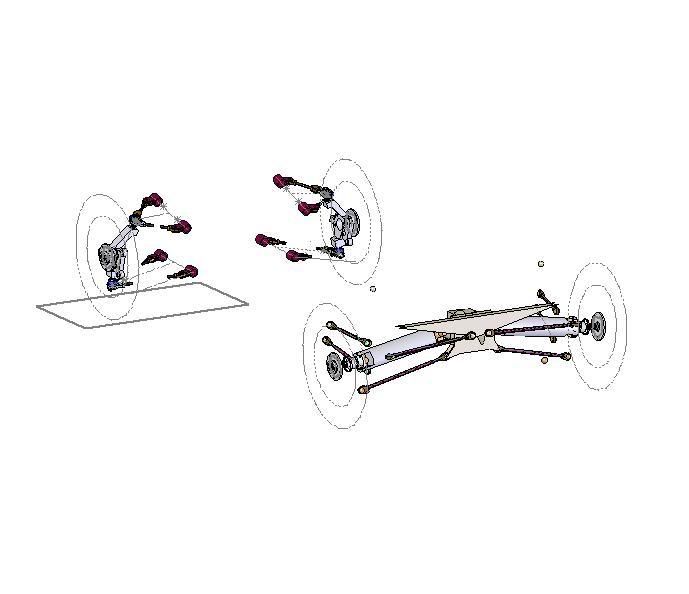
My suspension model is pretty decent.
In order to do what you want with the frame model, I'd have to get in and hollow it out, it's a solid, to the wall thicknesses on the car. Which is not constant, not to mention the overlapping pieces.
I really just use it to see if I have the mount locations correct.
In order to do what you want with the frame model, I'd have to get in and hollow it out, it's a solid, to the wall thicknesses on the car. Which is not constant, not to mention the overlapping pieces.
I really just use it to see if I have the mount locations correct.
Tech Contributor
Joined: Jun 2004
Posts: 20,910
Likes: 962
From: I tend to be leery of any guy who doesn't own a chainsaw or a handgun.
Going to be hard to do in the limited amount of space. But I can give you a few Ideas. You need to think way ahead if you are going to do a project like this. You cant build something with heims joints in it and expect it to make the car stiffer.
"So the C4 is about 850 lb-ft per degree...end to end. This is good to know."
It will be less than that. Bout 400-500 or so.
"So the C4 is about 850 lb-ft per degree...end to end. This is good to know."
It will be less than that. Bout 400-500 or so.
Thread Starter
Team Owner
Joined: Aug 2004
Posts: 21,543
Likes: 3,216
From: Park City Utah
Going to be hard to do in the limited amount of space. But I can give you a few Ideas. You need to think way ahead if you are going to do a project like this. You cant build something with heims joints in it and expect it to make the car stiffer.
"So the C4 is about 850 lb-ft per degree...end to end. This is good to know."
It will be less than that. Bout 400-500 or so.
"So the C4 is about 850 lb-ft per degree...end to end. This is good to know."
It will be less than that. Bout 400-500 or so.

Can you further explain your position on the torsional stiffness? I derived my number from the data that Aardwolf provided...