AC - FSM Diagram vs Actual
 07-24-2011, 12:28 AM
#1
Melting Slicks

Thread Starter

Wiring Schematic:

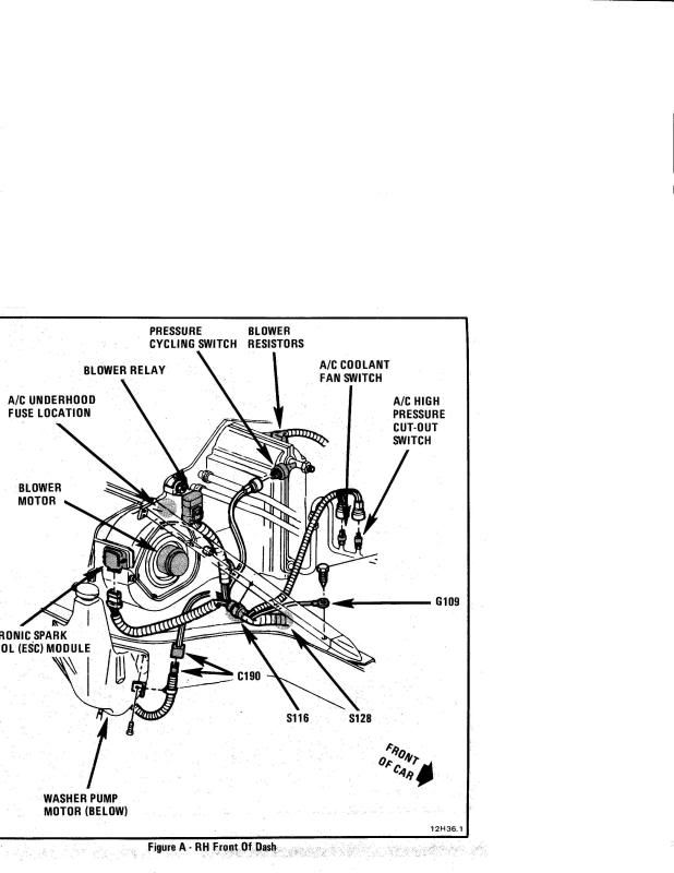
Diagram:

I'm reinstalling AC and the original engine harness is removed and replaced with DFI. The wiring for the compressor is in the engine harness so I am having to rewire a bit.
According to the wiring schematic the circuit goes through the "High Pressure Cut Out Switch" then the "Pressure Cycling Switch" which according to the Diagram is the switch closest to the big bend at the entrance to the evaporator.
The actual in car wiring goes through what is labeled in the diagram as the "High Pressure Switch" then through the "Pressure Cycling Switch"..NOT through the "High Pressure Cut Out Switch".
Anybody know what the "High Pressure Cut Out Switch" is actually wired to?? (There is no mention of it anywhere else in the AC wiring diagrams)
Diagram:
I'm reinstalling AC and the original engine harness is removed and replaced with DFI. The wiring for the compressor is in the engine harness so I am having to rewire a bit.
According to the wiring schematic the circuit goes through the "High Pressure Cut Out Switch" then the "Pressure Cycling Switch" which according to the Diagram is the switch closest to the big bend at the entrance to the evaporator.
The actual in car wiring goes through what is labeled in the diagram as the "High Pressure Switch" then through the "Pressure Cycling Switch"..NOT through the "High Pressure Cut Out Switch".
Anybody know what the "High Pressure Cut Out Switch" is actually wired to?? (There is no mention of it anywhere else in the AC wiring diagrams)

 07-24-2011, 08:58 AM
#3
Le Mans Master

..... The high pressure switch is wired in series with the other two ... high pressure switch is opened when the system pressure drops below 70 psi to prevent the compressor from running when the freon is low ... the high press cut-out stops the compressor when press gets too high ... i.e. : restriction or no fan = press above 400psi ..... the cycling switch opens when the system low side press drops below 25psi at the exit from the evaporator core to prevent freeze-up of the evap ... this can also be caused by a restricted orifice tube ...........
07-24-2011, 10:12 AM
#4
Melting Slicks

Member Since: Aug 1999
Location: Baltimore, MD USA
Posts: 2,240
Likes: 0
Received 34 Likes
on
30 Posts

Don't go by the position of the Pressure Cut Out switch and the
AC High Pressure switch as shown in the diagram. The fittings
on the metal tubing are the same so the switches can be mounted
in either position.
Here's the picture/diagram from the 89 manual. Notice
the AC High Pressure Cut Out switch is farthest from the
evaporator box. In reality on a 89 it's like the diagram
you posted and is closest to the evaporator box.
The High Pressure Cut Out switch has a connector with
a Light Green wire and a Black wire. The round connector is
physically larger than the AC High Pressure Switch and has
2 spade lugs.
The AC High Pressure Switch (Called the AC Coolant Fan Switch
on the 89) has a smaller connector with a Green wire and a
Black wire. The connector has a locking tab that must be pressed
to release it. The connector has two small round pins.
I'm assuming the following.
85 AC High Pressure Switch is the same as the AC Coolant Fan Switch
on a 89.
The ECM monitors the AC High Pressure Switch and turns the fan on when
the AC High pressure reaches around 240 psi.
Last edited by Hooked on Vettes; 07-24-2011 at 02:45 PM.
07-24-2011, 02:19 PM
#5
Melting Slicks
Thread Starter
Don't go by the position of the Pressure Cut Out switch and the
AC High Pressure switch as shown in the diagram. The fittings
on the metal tubing are the same so the switches can mounted
in either position.
Here's the picture/diagram from the 89 manual. Notice
the AC High Pressure Cut Out switch is farthest from the
evaporator box. In reality on a 89 it's like the diagram
you posted and is closest to the evaporator box.
I went back and checked the circuits and what is labeled in the 85 diagram as "HP Cut Out Switch" should be labeled as it is in the 89 diagram as AC Coolant Fan switch.
. The high pressure switch is wired in series with the other two
Modified the diagram to show what I found: (may need to click on the pic to blow up and read)

So, I think the technical explanations of the switches is right, it just appears when they labeled the diagram they used interchangeable terms to describe switches serving two different purposes.
07-25-2011, 12:30 PM
#6
Le Mans Master


Your fan is controlled by the ECM - it sends a reference to the on/off switch which is normally closed/grounded so the ECM senses 0 volts. When the switch opens, there's a voltage rise at the ECM and it drives the Fan. It doesn't matter where it's mounted as long as it's on the High (which is what the fan is engineered to control) - some designs put it on the head of the Compressor.
Low and High Cutouts are in series. High is usually a one time device and if it opens, it won't reset. Low is an on/off pegged to open with 25 psi (R12) and it'll reclose when system Pressure reaches 50 psi.
These early Years do not use the ECM for compressor clutch control. To maintain idle quality and to kickoff the clutch at WOT, there's a separate circuit from the Controls to the ECM. Make sure it's hooked up or it will stall when you hit the a/c request.
Electronic Controls are a bit more complicated using 3 separate circuits for clutch engagement - one through the low and high pressure switch; a second to the ECM and a third to switch on the ground for the Clutch Coil. The first 2 circuits have to be completed; ie, 0 volts at the Controls, before the clutch ground signal is sent/applied. That gives a tad better idle control, but not nearly as perfect as an ECM controlled clutch. It you're working with these Controls, you'll need that schematic.
07-25-2011, 01:44 PM
#7
Melting Slicks
Thread Starter
I have been wondering about this clutch disengagement at WOT. I always thought it did too but I just don't see how it's possible given the way it's wired. The schematic above continues by showing a splice into two circuits, one path to the ECM and one to the compressor.
If the the HVAC control head has AC selected, power flows through the control head, to the HP/Cycling switches, they close, power then flows to the compressor AND ECM. The ECM is not in a position to interrupt power or ground.
I don't see where the ECM could even cut power to the control head.
I'm not arguing BTW, I always thought the same thing, but now that I'm looking at it close, I don't see how the ECM could control the compressor.
There is a means to make sure IACs are kicked up to prevent stalling, but the compressor circuit itself is pretty simple. ECM seems to find out at the same time the compressor does, that the switches are closed.
What do you guys think, is it possible the ECM doesn't kick the clutch off at WOT?
And yes, I need to utilize the AC input on the DFI to make sure it kicks in a few IAC counts to prevent stalling.
07-25-2011, 05:18 PM
#8
Le Mans Master
It's not that complicated but it is somewhat convoluted. WOT or > 4 volts from the TPS, the ECM removes ground from the Panel reference signal. Panel voltage rises to the reference. Panel cuts power to the Compressor Circuit. That's why with these non ECM controlled Compressors, you usually experience a delay that you can feel if the a/c is engaged when you floor it. As the OEM's got into it, they also started removing ground based on Load - calculated from the MAF or MAP - and if I remember right, that showed up on the truck lines first. It became a lot better - allmost seamless - when the ECM took everything over. Diagnosing these earlier Years, if it isn't cutting out, is a nightmare. There are no troubletrees for the symptoms and you need to tape a gage set to the windshield and then capture data with your scanner when your floor it. Scan should switch the a/c request from "Yes" to "No"; TPS > 4 volts; gages should equalize at static pressure for ambient. Flooring it and immediately getting off of it doesn't give you enough time to capture it, so find a runway or dragstrip if you need to check it out. Then, once you've confirmed it isn't working, you can start guessing at what parts you need to replace and if it's a Panel, hope you can find a used one that still works. I've never seen any of the Tuners dig out or into this Programming either - though the ECM side is pretty simple - so if it's a custom tune, it many not work after you install it.
07-25-2011, 05:53 PM
#9
Le Mans Master
PS - above is for Electronic Controls which uses a separate a/c Panel signal. Manual is even easier. ECM a/c signal is spliced in series with the Low and High Pressure Cutout so at WOT, it's the same as when the Low Pressure Switch opens and the Compressor cycles - open circuit - and the ECM also loses the signal when it cycles which it needs to do if you don't want the idle hopping all over the place. The problems I've come across showed up in the ECM - 3 under warranty when my '89 was new because it wouldn't respond to an a/c yes/no with the idle going to hell as the first symptom. Anyway, if you're using Manual or a simple on/off, it shouldn't be that difficult to make it work, but it will depend on what's burned into the ECM (if it's not OEM); ie, is/was it designed to cut ground at WOT?