24x conversion...
 03-29-2012, 12:29 PM
#1
Burning Brakes

Thread Starter

Have you done one?
Was your cluster or DIC effected?
What is your engine setup?
I am curious. Looks like a brilliant idea to me!!
For those who dont know...
http://www.eficonnection.com/eficonnection/24x.aspx
this swap is popular with the f-body crowd.
Was your cluster or DIC effected?
What is your engine setup?
I am curious. Looks like a brilliant idea to me!!
For those who dont know...
http://www.eficonnection.com/eficonnection/24x.aspx
this swap is popular with the f-body crowd.
 03-29-2012, 12:58 PM
#2


Email I received from them wayback when:
Hi Will,
Installing everything but the engine wiring harness on a 95 Corvette should take no longer than about 4 hours. We offer no plug and play engine harness solution for the Corvette. I would recommend reworking the LT1 engine harness for LS1 PCM use. This requires time in the service manual and is something that only a few people have been willing to do. We offer no instructions regarding the harness rework.
To install the 58x system on an LT1, you�ll have to machine a distributor hole in the intake manifold. No customers have been willing to do this.
Thank you,
Mike Noonan
EFI Connection, LLC
03-29-2012, 02:33 PM
#3
Burning Brakes
Thread Starter
Yeah, I read most of that from thier site. I wonder if I made harnesses, people would buy them? Ive done this on my own from scratch converting 60* v6's to DIS. Not as bad as it seems.
03-29-2012, 03:09 PM
#4
Burning Brakes
Thread Starter
Just some random info I am going to put in this thread for future reference.
this is northstar on the LS1 PCM
Electronic Ignition (EI) System Description
The Ignition Control System for this Powertrain controls fuel combustion by providing a spark to ignite the compressed air/fuel mixture in each cylinder at the correct time. The ignition control system has several advantages over a mechanical distributor ignition system.
The Ignition Control System does not use a conventional distributor or a single ignition coil. In this ignition system, both ends of each of the four ignition coils are connected to a spark plug. Each coil is connected with spark plugs on companion cylinders, i.e., on top dead center at the same time (1-4, 2-5, 6-7, and 3-8). One cylinder is on its compression stroke when the other one is on its exhaust stroke.
When the coil discharges, both plugs fire at the same time by using the engine block to complete the electrical circuit. The cylinder on the compression stroke is called the event cylinder and the one on the exhaust stroke is the waste cylinder. The two cylinders share the energy available from the ignition coil to fire both spark plugs. This method of ignition is called waste spark ignition.
Since the polarity of the ignition coil primary and secondary windings does not change, one spark plug always fires with a forward current (center electrode to ground electrode) and its companion plug fires with a reverse current (ground electrode to center electrode). This is different from a conventional distributor ignition system that fires all the plugs with the same forward current flow.
It is possible for one spark plug to fire even though a plug wire from the same coil may be disconnected from its companion spark plug. The disconnected plug wire acts as one plate of a capacitor and the engine block acts as the other plate. These two capacitor plates are charged as a spark first jumps across the gap of the connected spark plug. The plates are then discharged as the energy is dissipated as the spark continues. Voltage requirements are very high with an open spark plug or wire. The ignition coil may have enough reserve energy to fire the connected plug at idle, but possibly not under some engine load conditions. A more noticeable misfire may be evident under load; both spark plugs may then not fire.
Crankshaft Position Sensors and Reluctor Ring
The two crankshaft sensors are located on the front bank (BANK 2) of the engine block between cylinders 4 and 6. Crankshaft position A sensor is located in the upper crankcase and crankshaft position B sensor is located in the lower crankcase. Both sensors extend into the crankcase and are sealed to the engine block with O-rings. The crankshaft position sensors are not adjustable.
The magnetic crankshaft position sensors operate similar to the pickup coil in a distributor. When a piece of steel (called a reluctor) is repeatedly moved over the sensor, a voltage will be created by the sensor that appears to go On-Off-On-Off-On-Off. This On-Off signal is also similar to the signal that a set of breaker points in a distributor would generate as the distributor shaft turned and the points opened and closed.
The reluctor ring is cast onto the crankshaft between the #3 and #4 main bearing journals. The reluctor ring has 24 evenly spaced notches or air gaps and an additional 8 unevenly spaced notches for a total of 32.
As the crankshaft makes one complete revolution, both the A and B sensors will produce 32 On-Off pulses per revolution. In addition, the A sensor is positioned 27 degrees of crankshaft revolution before the B sensor. This creates a unique pattern of On-Off pulses sent to the ignition control module so that it can recognize crankshaft position.
Camshaft Sensor
The camshaft position sensor is located on the rear cylinder bank (BANK 1) in front of the exhaust camshaft. The camshaft position sensor extends into the rear cylinder head and is sealed with an O-ring. The camshaft position sensor is not adjustable.
As the rear cylinder bank exhaust camshaft turns, a steel pin on its drive sprocket passes over the magnetic camshaft position sensor. This creates an On-Off-On-Off signal sent to the ignition control module similar to the crankshaft position sensors. The camshaft position sensor produces one On-Off pulse for every one revolution of the camshaft or every two revolutions of the crankshaft. This allows the ignition control module to recognize camshaft position.
Ignition Control Module
The Ignition Control (IC) module is located on top of the rear camshaft cover. The IC module performs several functions:
Four separate coils are mounted to the module assembly. Each coil provides the spark for two spark plugs simultaneously (wasted spark ignition). Each coil can be replaced separately.
Base Ignition Timing
The base ignition timing is determined by the relationship of the crankshaft position sensors to the reluctor ring. This relationship is not adjustable and results in a base ignition timing of 10 degrees BTDC.
IC Module Mode
There are two modes of ignition system operation: PCM mode and Ignition Control Module (IC Module) mode. In IC Module mode, the ignition system operates independently from the PCM. The ignition control module maintains a base ignition timing of 10 degrees BTDC and is able to change this ignition timing slightly with increased engine speed. IC Module mode is in effect whenever an ignition control fault is detected while the engine is running and it will have a noticeable effect on driveability. In PCM mode, the PCM controls the ignition timing. The PCM calculates the desired ignition timing based on information it receives from the input sensors.
PCM Timing Mode
The Powertrain Control Module (PCM) controls spark advance and fuel injection for all driving conditions. The PCM monitors input signals from the following components as part of its ignition control function to determine the required ignition timing:
this is northstar on the LS1 PCM
Electronic Ignition (EI) System Description
The Ignition Control System for this Powertrain controls fuel combustion by providing a spark to ignite the compressed air/fuel mixture in each cylinder at the correct time. The ignition control system has several advantages over a mechanical distributor ignition system.
- No moving parts to wear out.
- No mechanical load on the engine.
- Elimination of mechanical timing adjustments.
- Located for easier service and improved reliability.
- Improved high engine speed performance.
- Two crankshaft position sensors (A and B).
- Crankshaft reluctor ring.
- Camshaft position sensor.
- Ignition control module.
- 4 separate ignition coils.
- Eight spark plug wires and conduit.
- Eight spark plugs.
- Knock sensor.
- Powertrain Control Module (PCM).
The Ignition Control System does not use a conventional distributor or a single ignition coil. In this ignition system, both ends of each of the four ignition coils are connected to a spark plug. Each coil is connected with spark plugs on companion cylinders, i.e., on top dead center at the same time (1-4, 2-5, 6-7, and 3-8). One cylinder is on its compression stroke when the other one is on its exhaust stroke.
When the coil discharges, both plugs fire at the same time by using the engine block to complete the electrical circuit. The cylinder on the compression stroke is called the event cylinder and the one on the exhaust stroke is the waste cylinder. The two cylinders share the energy available from the ignition coil to fire both spark plugs. This method of ignition is called waste spark ignition.
Since the polarity of the ignition coil primary and secondary windings does not change, one spark plug always fires with a forward current (center electrode to ground electrode) and its companion plug fires with a reverse current (ground electrode to center electrode). This is different from a conventional distributor ignition system that fires all the plugs with the same forward current flow.
It is possible for one spark plug to fire even though a plug wire from the same coil may be disconnected from its companion spark plug. The disconnected plug wire acts as one plate of a capacitor and the engine block acts as the other plate. These two capacitor plates are charged as a spark first jumps across the gap of the connected spark plug. The plates are then discharged as the energy is dissipated as the spark continues. Voltage requirements are very high with an open spark plug or wire. The ignition coil may have enough reserve energy to fire the connected plug at idle, but possibly not under some engine load conditions. A more noticeable misfire may be evident under load; both spark plugs may then not fire.
Crankshaft Position Sensors and Reluctor Ring
The two crankshaft sensors are located on the front bank (BANK 2) of the engine block between cylinders 4 and 6. Crankshaft position A sensor is located in the upper crankcase and crankshaft position B sensor is located in the lower crankcase. Both sensors extend into the crankcase and are sealed to the engine block with O-rings. The crankshaft position sensors are not adjustable.
The magnetic crankshaft position sensors operate similar to the pickup coil in a distributor. When a piece of steel (called a reluctor) is repeatedly moved over the sensor, a voltage will be created by the sensor that appears to go On-Off-On-Off-On-Off. This On-Off signal is also similar to the signal that a set of breaker points in a distributor would generate as the distributor shaft turned and the points opened and closed.
The reluctor ring is cast onto the crankshaft between the #3 and #4 main bearing journals. The reluctor ring has 24 evenly spaced notches or air gaps and an additional 8 unevenly spaced notches for a total of 32.
As the crankshaft makes one complete revolution, both the A and B sensors will produce 32 On-Off pulses per revolution. In addition, the A sensor is positioned 27 degrees of crankshaft revolution before the B sensor. This creates a unique pattern of On-Off pulses sent to the ignition control module so that it can recognize crankshaft position.
Camshaft Sensor
The camshaft position sensor is located on the rear cylinder bank (BANK 1) in front of the exhaust camshaft. The camshaft position sensor extends into the rear cylinder head and is sealed with an O-ring. The camshaft position sensor is not adjustable.
As the rear cylinder bank exhaust camshaft turns, a steel pin on its drive sprocket passes over the magnetic camshaft position sensor. This creates an On-Off-On-Off signal sent to the ignition control module similar to the crankshaft position sensors. The camshaft position sensor produces one On-Off pulse for every one revolution of the camshaft or every two revolutions of the crankshaft. This allows the ignition control module to recognize camshaft position.
Ignition Control Module
The Ignition Control (IC) module is located on top of the rear camshaft cover. The IC module performs several functions:
- It monitors the On-Off pulses produced by the two crankshaft and one camshaft position sensors.
- It creates a 4X and 24X reference signal (4X REF HI and 24X Crank) sent to the PCM for ignition control.
- It creates a camshaft reference signal (CAM HI) sent to the PCM for fuel injection control.
- It provides a ground reference (REF LO, CAM LO) to the PCM.
- It provides a means for the PCM to control spark advance (BYPASS and IGNITION CONTROL) called IGNITION CONTROL MODE.
- It provides a limited means of controlling spark advance without PCM input called MODULE MODE.
- The IC module is not repairable. When a module is replaced the remaining components must be transferred to the new module.
Four separate coils are mounted to the module assembly. Each coil provides the spark for two spark plugs simultaneously (wasted spark ignition). Each coil can be replaced separately.
Base Ignition Timing
The base ignition timing is determined by the relationship of the crankshaft position sensors to the reluctor ring. This relationship is not adjustable and results in a base ignition timing of 10 degrees BTDC.
IC Module Mode
There are two modes of ignition system operation: PCM mode and Ignition Control Module (IC Module) mode. In IC Module mode, the ignition system operates independently from the PCM. The ignition control module maintains a base ignition timing of 10 degrees BTDC and is able to change this ignition timing slightly with increased engine speed. IC Module mode is in effect whenever an ignition control fault is detected while the engine is running and it will have a noticeable effect on driveability. In PCM mode, the PCM controls the ignition timing. The PCM calculates the desired ignition timing based on information it receives from the input sensors.
PCM Timing Mode
The Powertrain Control Module (PCM) controls spark advance and fuel injection for all driving conditions. The PCM monitors input signals from the following components as part of its ignition control function to determine the required ignition timing:
- Ignition Control Module (IC Module).
- Engine Coolant Temperature (ECT) sensor.
- Manifold Absolute Pressure (MAP) sensor.
- Transaxle Range (TR) switch.
- Throttle Position (TP) sensor.
- Vehicle Speed Sensor (VSS).
- Knock Sensor (KS).
- The crankshaft reluctor ring has 24 evenly spaced notches plus 8 additional notches (shaded) used for synchronization.
- As the crankshaft rotates, the notches pass the position sensors and create a voltage pulse signal in the sensor that is an input for the ignition control module (ICM).
- Because of the physical location of the 2 crankshaft position sensors, the signal of B lags the signal of A by 27 degrees of crankshaft revolution.
- To synchronize the ignition, the ICM first counts the number of B pulses between every 2 A pulses. There can be 0, 1, or 2 B pulses between A pulses.
- When the ICM sees 0 B pulses between A pulses , it starts counting B pulses between A pulses. When the ICM counts exactly 4, it synchronizes the ignition on the very next A pulse. If the ICM counts over 4 (jumps from 3 to 5), it waits for another B pulse between A pulse to start counting again.
- This process allows the ignition to synchronize and fire the first spark plug within 180 degrees (1/2 engine revolution).
- The camshaft position (CMP) sensor provides the ICM with cylinder #1 firing order information, which the PCM uses for sequential fuel injection.
- Using 3 sensors allows the ICM to maintain ignition synchronization even if one of the 3 sensors fails.
Last edited by merlot566jka; 03-29-2012 at 03:11 PM.
03-29-2012, 03:17 PM
#5
Burning Brakes
Thread Starter
From http://chevythunder.com/ls1_page_1.htm
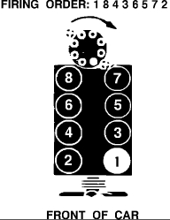
Firing order: 1-8-7-2-6-5-4-3
The firing order of the LS1/Vortec V8 has been revised from the Gen I and Gen II engines. This was done to provide more power, less crankshaft rotational stress and better emission and idle qualities.
Camshaft sensor (CMP)
The camshaft sensor is a 1X pulse sensor which is synchronized to the #1 firing of the engine (Whether or not it is on its firing or exhaust stroke). The reluctor is located on the back of the camshaft. As the reluctor rotates, it interrupts the magnetic field produced by the sensor and the pcm interprets this as a pulse, after the signal is buffered by the internal circuitry of the CMP. The pcm uses this signal in conjunction with the crankshaft sensor (CKP) to determine the crank position and stroke. The pcm monitors this signal for any problems and sets the appropriate DTC (diagnostic trouble code) for loss or degraded signal. The pcm provides the +12V power, ground and signal return for the CMP.
A loss of this signal will result in longer starting times.


The LS1-Vortec V6 camshaft sensor (CMP) The location of the CMP is on the top rear center of block
Crankshaft sensor (CKP)
The crankshaft sensor is a 24X (58X on 2004 and later engines) pulse sensor that controls ignition coil firing and injector pulse. The 24 tooth reluctor wheel is mounted on the back of the crankshaft. This location is known as the "quiet" deflection zone that minimizes any false signals to the pcm that can be misinterpreted as a fault. As with the CMP, the crankshaft sensor is a magnetic sensor that has the field interrupted by the passing the the teeth on the reluctor. This signal is conditioned by the sensor circuitry so I can be properly used by the pcm.
The pcm constantly times the pulse intervals it receives, in conjunction with the CMP to resync the point of the #1 firing stroke. Any changes to the timed intervals at each firing order stroke is read by the pcm as a change in crankshaft velocity. Using the other sensors such a MAP, and TPS, the pcm can determine the changes in crankshaft speed when the engine is accelerating or decelerating, within normal operating conditions, and when the changes are outside the normal parameters, the pcm detects this as a misfire, and the appropriate DTC is set.
A loss of this signal will result in a no-start condition


The LS1-Vortec V8 Crank sensor (CKP) The location of the CKP is on the right hand side above the starter.
The 24X reluctor crank sensor has a black connector plug, the 58X reluctor sensor connector is gray in color. This does not interchange and must be used with the proper reluctor shown below.
Crankshaft Reluctors:

The 24X reluctor is on the left, the 58X reluctor on the right.
Firing order: 1-8-7-2-6-5-4-3
The firing order of the LS1/Vortec V8 has been revised from the Gen I and Gen II engines. This was done to provide more power, less crankshaft rotational stress and better emission and idle qualities.
Camshaft sensor (CMP)
The camshaft sensor is a 1X pulse sensor which is synchronized to the #1 firing of the engine (Whether or not it is on its firing or exhaust stroke). The reluctor is located on the back of the camshaft. As the reluctor rotates, it interrupts the magnetic field produced by the sensor and the pcm interprets this as a pulse, after the signal is buffered by the internal circuitry of the CMP. The pcm uses this signal in conjunction with the crankshaft sensor (CKP) to determine the crank position and stroke. The pcm monitors this signal for any problems and sets the appropriate DTC (diagnostic trouble code) for loss or degraded signal. The pcm provides the +12V power, ground and signal return for the CMP.
A loss of this signal will result in longer starting times.
The LS1-Vortec V6 camshaft sensor (CMP) The location of the CMP is on the top rear center of block
Crankshaft sensor (CKP)
The crankshaft sensor is a 24X (58X on 2004 and later engines) pulse sensor that controls ignition coil firing and injector pulse. The 24 tooth reluctor wheel is mounted on the back of the crankshaft. This location is known as the "quiet" deflection zone that minimizes any false signals to the pcm that can be misinterpreted as a fault. As with the CMP, the crankshaft sensor is a magnetic sensor that has the field interrupted by the passing the the teeth on the reluctor. This signal is conditioned by the sensor circuitry so I can be properly used by the pcm.
The pcm constantly times the pulse intervals it receives, in conjunction with the CMP to resync the point of the #1 firing stroke. Any changes to the timed intervals at each firing order stroke is read by the pcm as a change in crankshaft velocity. Using the other sensors such a MAP, and TPS, the pcm can determine the changes in crankshaft speed when the engine is accelerating or decelerating, within normal operating conditions, and when the changes are outside the normal parameters, the pcm detects this as a misfire, and the appropriate DTC is set.
A loss of this signal will result in a no-start condition
The LS1-Vortec V8 Crank sensor (CKP) The location of the CKP is on the right hand side above the starter.
The 24X reluctor crank sensor has a black connector plug, the 58X reluctor sensor connector is gray in color. This does not interchange and must be used with the proper reluctor shown below.
Crankshaft Reluctors:
The 24X reluctor is on the left, the 58X reluctor on the right.
03-29-2012, 03:22 PM
#6
Burning Brakes
Thread Starter
And almost a repeat... witha little more info... from http://lukeskaff.com/?page_id=380
GM Cadillac Northstar DIS to GM HEI SBC ECM Project
Project Status: Discontinued
Project Started: Fall 2005
1. Introduction
I did not originally think of this idea but have done a great deal of research on the operation and components in the first generation 1990's (93-99) Cadillac northstar ignition setup. I have put together a lot of useful information for anyone looking to complete this project or modify the Northstar DIS setup for use on there car. These pages outline some of the needed information to run a Cadillac northstar DIS (distributorless ignition system) ignition module and coils on a SBC with almost any GM OBD-I HEI ECM \ ECU. I planed to use this on a 1227730 90-92 f-body or 1227727 90-91 C4 Y-body speed density ECM.
The Cadillac northstar first generation ignition system was used on the following vehicles:
BrandVehicleYearCADILLACALLANTE1993CADIL LACDEVILLE1996 - 1999CADILLACDEVILLE CONCOURS1994 - 1999CADILLACDEVILLE DELEGANCE1997CADILLACELDORADO1994 - 1999CADILLACELDORADO ETC1998CADILLACELDORADO SPORT1993CADILLACELDORADO TOURING1993 - 1997CADILLACSEVILLE1999CADILLACSEVILLE SLS1994 - 1998CADILLACSEVILLE STS1993 - 1998OLDSMOBILEAURORA1995 - 1999
2. Cadillac Northstar DIS Theory & Operation
2.1) Overview
The Cadillac Northstar ignition system on a factory 1993-1999 Northstar engine is composed of an ignition module, four coils, a crankshaft trigger wheel, two variable reluctance crankshaft position sensors, and a cam sensor used for SFI operation by the PCM. The two crankshaft position sensors are used to quickly determine crankshaft position for fast engine starting, know as "Fast-Start". Using two crankshaft sensors allows the ignition module to determine the engine position within 180 degrees of rotation of the crankshaft. Another benefit of two crankshaft sensors is redundancy; in case one sensor fails, the module can operate off the remaining working sensors. If you are running two crank sensors and a cam sensor any one sensor can fail, including one of the crank sensors and the module will continue to operate. If you operate the module without a cam sensor both crank sensors are needed to maintain operation.
2.2) Crankshaft Trigger Wheel (reluctor ring)
The Northstar crankshaft has a trigger wheel (also called a reluctor ring) cast into the crankshaft between #3 and #4 main bearings. Two crankshaft position sensors are installed into the side of the engine block (facing front of car in FWD applications) between cylinders 4 and 6. The trigger wheel has 32 notches, 16 large raised areas, and 16 small raised areas, as seen in Figure 1 and 2 below.
Figure 1: GM drawing of Northstar trigger wheel
Image from GM, Cadillac division.
Figure 2: Cadillac Northstar crank trigger wheel put into CAD
Note: Drawing not to scale, for accurate scaled version download the the CAD or PDF drawing below.
Each notch and small raised area is 1/3 the size of the large raised area. In the GM drawing of the Northstart in Figure 1 you can see that they blacked out the notches between the small raised areas to create 24 even notches and large raised areas. This is why GM considers this a 24x trigger wheel. The eight uneven notches are used by the ignition module to determine crankshaft position to determine which cylinder is next in the firing order.
2.3) Northstar PCM & ICM wiring
Note: The firing order above is that of a GM northstar block and must be changed for SBC applications, see below
2.4) Crankshaft Position sensors
The two crankshaft position sensors used in the Northstar setup are variable reluctance sensors separated 27 degrees apart. Each sensor is mounted within a tight tolerance of the trigger wheel (reluctor wheel), 0.05" (1.3mm) on the factory engine.
2.5) Camshaft Position sensors
A camshaft position sensor is not needed on HEI ECM conversions because they are bank fire applications this is only needed for SFI PCM's.
The camshaft position sensor is positioned over a dowel pin located on the exhaust camshaft cam gear. One Off-On-Off signal pulse is created every camshaft rotation and every two crankshaft rotations.
2.6) Coils
The four coils used in the Northstar setup employ a waste spark firing method. Waste spark firing means that two spark plugs are fired at one time thus lowering the number of coils needed and the cost. When a coil fires of the two cylinders fired, one is on the compression stroke and one is on the exhaust stroke.
2.7) Ignition Control Module
The Northstar ignition control module is what processes the input from three sensors and the proper signal output to the ECM \ ECU \ PCM.
It performs the following functions and more:
- It monitors the On-Off pulses produced by the two crankshaft and one camshaft position sensors.
- It creates a 4X and 24X reference signal (4X REF HI and 24X Crank) sent to the PCM for ignition control.
- It creates a camshaft reference signal (CAM HI) sent to the PCM for fuel injection control.
- It provides a ground reference (REF LO, CAM LO) to the PCM.
- It provides a means for the PCM to control spark advance (BYPASS and IGNITION CONTROL) called IGNITION CONTROL MODE.
- It provides a limited means of controlling spark advance without PCM input called MODULE MODE.
- The IC module is not repairable. When a module is replaced the remaining components must be transferred to the new module.
2.8) Ignition Synchronization
Ignition Control Module signal descriptionSingleSignal NameVoltage RangeDescriptionACrankshaft position sensor 'A'+/- 100V AC Voltage and frequency vary with engine speedBCrankshaft position sensor 'B'+/- 100V AC Voltage and frequency vary with engine speed. Signal lags crankshaft position sensor 'A' by 27
degreesCCamshaft position sensor+/- 100V AC Voltage and frequency vary with engine speedThis signal occurs every two crankshaft revolutionsD4X Ref Hi0 - 5V DC Key on, Engine Off: Signal is high. High to low occurs at first sync, then follows firing order.EBypass0 - 5V DC Key on, Engine Off: Signal is low. Low to High occurs with PCM ignition control.FIgnition control0 - 5V DC PCM sends ignition control signal to ICM. The falling edge signals ICM to turn off coil primary
current.G24X Crank0 - 5V DC This signal will remain high if the ICM identifies a fault with one of its three position sensortsH1/2x Cam Hi0 - 5V DC The PCM uses this signal for sequential (SFI) fuel controlIGround Ref.0V DC This is the ground reference between the PCM and ICM
1) The crankshaft reluctor ring has 24 evenly spaced notches plus eight additional notches (shaded) used for synchronization for a total of 32 notches.
2) As the crankshaft rotates, the notches pass the position sensors and create a voltage pulse signal in the sensor that is an input for the ignition control module (ICM).
3) Because of the physical location of the 2 crankshaft position sensors, the signal of B lags the signal of A by 27 degrees of crankshaft revolution.
4) To synchronize the ignition, the ICM first counts the number of B pulses between every 2 A pulses. There can be 0, 1, or 2 B pulses between A pulses.
5) When the ICM sees 0 B pulses between A pulses , it starts counting B pulses between A pulses. When the ICM counts exactly 4, it synchronizes the ignition on the very next A pulse. If the ICM counts over 4 (jumps from 3 to 5), it waits for another B pulse between A pulse to start counting again.
6) This process allows the ignition to synchronize and fire the first spark plug within 180 degrees (1/2 engine revolution).
7) The camshaft position (CMP) sensor provides the ICM with cylinder #1 firing order information, which the PCM uses for sequential fuel injection.
8) Using 3 sensors allows the ICM to maintain ignition synchronization even if one of the 3 sensors fails.
2.9) Firing Order:
To run the northstar ignition module on a SBC you will connect the wires to the coils as follows.
1'st Gen Northstar Firing order
1-2-7-3-4-5-6-8
1'st Gen SBC Firing Order:
1-8-4-3-6-5-7-2 looking at the front of the motor counting back: driver side (right) = 1-3-5-7 pass side (left) = 2-4-6-8
2.10) Ignition Control Module Pinouts:
I have created a column in the tables below to outline which pins would be used if using the northstar ignition module on a 1227730, 1227727, or pretty much any HEI distributor OBD-I GM car.
Connector 1 - Crankshaft SensorsPinUsed on HEI ECMFunctionAYes Crankshaft sensor A high signalBYes Crankshaft sensor A low signalCNo Not UsedDNo Not UsedENo Crankshaft sensor B low signalFNo Crankshaft sensor B high signal
Connector 2 - Power and Tachometer outputPinUsed on HEI ECMFunctionAYes GroundBYes Tachometer signal outputCYes Ignition controlled battery voltage
Connector 3 - Cam sensorPinUsed on HEI ECMFunctionANo Camshaft sensor high outputBNo Camshaft sensor low outputCNo Not Used
Connector 4 - PCM \ ECM OutputPinUsed on HEI ECMFunctionANo 24x spark reference signalBNo 1/2x cam signalCYes 4x fuel control signalDYes Ignition bypassEYes Ignition controlFYes Ignition reference low
3. Trigger Wheel Design & Fabrication
3.1) Crankshaft Trigger Wheel
I purchased a used Northstar crankshaft off eBay to get the measurements of the trigger wheel and create the wheel in CAD. Here are the measurements of the Northstar trigger wheel:
Most measurements taken from the trigger wheel are giving in a range because measurements taken at different points of the wheel yielded different results, this is due to machining tolerances of the wheel. The tolerances of the wheel do not need to be very close, the notch position and size is what is important so the module can figure out where the engine is in rotation. Each of the 32 notches on the crank trigger wheel is about 15/64 (or 0.235 to be exact) of an inch in length and 3/16 - 13/64 of a inch deep. There are 16 small raised areas which are about the same length as the notches, they are about 7/32 (0.21 - 0.215) of a inch. There are 16 large raised areas which are about 3 times the length of the notches and measure in at 0.66 - 0.665 of a inch. So calculating in a percent of error for machining tolerances, each notch and small raised area are the same length. The large raised area is three times the length of the notches.
The above broken down into degrees:
- 32 notches 3.75 degrees in length
- 16 small raised areas 3.75 degrees in length
- 16 large raised areas 11.25 degrees in length
The thickness of the trigger wheel is 9/32 - 5/16 of a inch thick, the thickness is different at different points around the wheel due to the fact that one side of the wheel is un-machined cast and the other is machined flat.. The diameter of the trigger wheel is about 6 & 15/16 inches.
3.2) Northstar Crankshaft Trigger Wheel CAD
Here is the AutoCAD file of the Northstar trigger wheel, this can be scaled in size as needed:
Northstar trigger wheel (AutoCAD File)
Northstar trigger wheel (PDF File, only for viewing purposes)
03-29-2012, 03:27 PM
#7
Burning Brakes
Thread Starter
MOAR
http://ls1tech.com/forums/generation...ientation.html
From Fiero.nl
http://www.fiero.nl/forum/Forum2/HTML/087521-2.html
blend of info on opti, ls1 and ltcc
http://www.fiero.nl/forum/Forum2/HTML/120549-2.html
from the depths of this forum, found out info on the ltcc
http://forums.corvetteforum.com/c4-t...onversion.html
Last edited by merlot566jka; 03-29-2012 at 03:41 PM.
03-30-2012, 01:11 AM
#8
This might be worth it for those with built motors or superchargers?
However, if the cost of the system is a few grand, you aren't that far off from purchasing an LS1 and just doing a swap...?
However, if the cost of the system is a few grand, you aren't that far off from purchasing an LS1 and just doing a swap...?
03-30-2012, 09:20 AM
#9
Burning Brakes
Thread Starter
Well thats why I am posting all of this information, hopefully you guys see what I am aiming for. Its not to get information about it, its to take information and do something with it.
When I made a DIS system in the past, it was all from scratch. There is no need to buy hundreds of dollars of stuff to make it work. In reality all you need is a reluctor wheel, PCM, and 1x cam signal. The crank sensor can be found at a salvage yard for a couple bucks. The reluctor wheel can be found for that cheap or free... the problem is to adapt it to our cars. If I were to make my own reluctor wheel that can go on externally, and a bracket to hold the sensor, then the only other issue is the cam signal, which I am fairly certain that will be easy as pie. Re-pinning the ecm is a little time consuming, but not overly difficult. And once its done right, there is not trouble after, and its easier for the next guy after it is well laid out on a spreadsheet
The other option is how the LTCC take the signal from the optical side of the opti, and uses that as the crank signal. If we can take the opti's signal, and make the LS1 pcm work on it, we could almost have an entirely plug and play LS1 PCM conversion.
You may ask "why all this trouble, my PCM works fine"
Or
Well yes, it would help the forced induction guys a bunch. But that is not the objective. The LS1 PCM is considerably faster, the coil on plugs provide better spark, it controlls fuel better and with the added control gas mileage should improve. Tuning takes leaps and bounds in the DIY enviroment. I am not 100% yet, but I am pretty sure the ls1 pcm can be tuned with an iPhone. That says it all to me.
Take the cost away from the equation, and its a no brainer. But with the added cost from EFI connection, and the no support for the C4 and this is a huge "no way". Plus the disasembly to mount a new timing cover, remove the opti etc etc, its not an easy thing to sell, you would almost have to have no other choice to chose this.
Now from my prospective (a resourceful and intelligent, read:CHEAP) and things can be done for alot less. This jumps the cost hurtle. The production for a mass is something I have never done, so I can only assume that once I have a working prototype, production afterwords will be considerably less. I cant put a price to it yet, but this thousand dollar business is retarded if you ask me. I am not in this to make a buck, I make enough at work, in the naval reserves, and from the GI Bill. I am in this to make a product that works for the C4 crowd. And the c4 crowd is usally on the skeptical side, and rarely strays away from what is offered in a cataloge or from GM. So it becomes difficult.
Anyway, this thread is for the technical aspect of this. The production and sale of it will be further down the line.
When I made a DIS system in the past, it was all from scratch. There is no need to buy hundreds of dollars of stuff to make it work. In reality all you need is a reluctor wheel, PCM, and 1x cam signal. The crank sensor can be found at a salvage yard for a couple bucks. The reluctor wheel can be found for that cheap or free... the problem is to adapt it to our cars. If I were to make my own reluctor wheel that can go on externally, and a bracket to hold the sensor, then the only other issue is the cam signal, which I am fairly certain that will be easy as pie. Re-pinning the ecm is a little time consuming, but not overly difficult. And once its done right, there is not trouble after, and its easier for the next guy after it is well laid out on a spreadsheet
The other option is how the LTCC take the signal from the optical side of the opti, and uses that as the crank signal. If we can take the opti's signal, and make the LS1 pcm work on it, we could almost have an entirely plug and play LS1 PCM conversion.
You may ask "why all this trouble, my PCM works fine"
Or
This might be worth it for those with built motors or superchargers?
However, if the cost of the system is a few grand, you aren't that far off from purchasing an LS1 and just doing a swap...?
However, if the cost of the system is a few grand, you aren't that far off from purchasing an LS1 and just doing a swap...?
Take the cost away from the equation, and its a no brainer. But with the added cost from EFI connection, and the no support for the C4 and this is a huge "no way". Plus the disasembly to mount a new timing cover, remove the opti etc etc, its not an easy thing to sell, you would almost have to have no other choice to chose this.
Now from my prospective (a resourceful and intelligent, read:CHEAP) and things can be done for alot less. This jumps the cost hurtle. The production for a mass is something I have never done, so I can only assume that once I have a working prototype, production afterwords will be considerably less. I cant put a price to it yet, but this thousand dollar business is retarded if you ask me. I am not in this to make a buck, I make enough at work, in the naval reserves, and from the GI Bill. I am in this to make a product that works for the C4 crowd. And the c4 crowd is usally on the skeptical side, and rarely strays away from what is offered in a cataloge or from GM. So it becomes difficult.
Anyway, this thread is for the technical aspect of this. The production and sale of it will be further down the line.
03-30-2012, 10:38 AM
#10
Safety Car


I got a price of $2580 from them for the complete system:
$825.00 for 24x Crank/Cam components and billet timing cover (http://www.eficonnection.com/eficonn...spx?ItemId=803)
$515.00 for Coil Bracket Assemblies (http://www.eficonnection.com/eficonn...spx?ItemId=808)
$480.00 for Monoblade Throttle Body (http://www.eficonnection.com/eficonn...spx?ItemId=902)
$110.00 for Used LS1 PCM (http://www.eficonnection.com/eficonn...spx?ItemId=729)
$650.00 for stand alone wire harness (http://www.eficonnection.com/eficonn...spx?ItemId=849)
That's for WAY more than someone would need for just an ECM "upgrade"...I needed the monoblade throttle body anyway...so that puts it just over $2k.
...Jegs has the FAST XFI w/logging + traction control for about $2k.
There are also added benefits to this:
1) Parts are readily available from salvage yards
2) Parts can be purchased at any GM dealership or aftermarket parts house (i.e. Pep Boys)
3) You don't have to wait 2+ weeks on an ECM to be replaced when you can just drive down the road and buy one.
4) There are dozens of tuning tools for the LS-series ECM's
5) There are WAY more "tuners" about for these LS ECM's than FAST could ever hope for...many of them local to you.
I'm going to do this for my 427...it makes no sense not to. I bought a rolling shell to build a racer out of, and it came with no computer. I was going to need something better than the C4 OEM ECM anyway.
Last edited by 1991Z07; 03-30-2012 at 11:03 AM.
03-30-2012, 10:39 AM
#11
Instructor

I have the EFI 24x setup running on my lt1 in a camaro. I repinned my harness myself, so the total kit cost was around 850 for the kit from efi connection if I recall. I spent another 200 on brand new ls2 coils on ebay. Took me about 8 hours to repin and it fired up first try. so for 1k I was up and running.
my motor is highly worked heads, full headers, ported intake, etc with pretty decent lumpy cam 233/241 600/600 and it drives smooth as silk (~400rwhp). I like not having the opti for sure and now I can tune the car with HP tuners.
The only thing I would have done differently is let EFI build my harness. for $850 to get a complete custom brand new harness that is plug and play would have been worth it completely. If I find a C4 roller that I can drop this motor in, I will go that route for sure. This is a high quality setup in my opinion that is really completely plug and play compared all the previous posts above.
03-30-2012, 06:10 PM
#13
I would like these benefits to my LT1, and if you are able to make a system work, consider me greatly interested.
 03-31-2012, 03:12 PM
#14
Le Mans Master

I have someone that can re-do the wiring harness if someone is really interested in doing this. Shoot me a PM and give me your contact info and I'll pass it along to him.
03-31-2012, 04:39 PM
#15
Le Mans Master
 I'm glad to see you looking into this. I've kicked around this idea for a few years but I'm dead in the water on my transmission swap right now so I know that doing this is further down the line. I like the LS1 and newer PCMs and realize that the PCM combined with DIS represents a significant leap forward. I've sometimes wondered how much power and efficiency can be found in just the improved ignition and finer tuning potential of the newer systems. If I didn't work so much and had a newborn I'd probably be digging into this more myself.
04-02-2012, 10:56 AM
I'm glad to see you looking into this. I've kicked around this idea for a few years but I'm dead in the water on my transmission swap right now so I know that doing this is further down the line. I like the LS1 and newer PCMs and realize that the PCM combined with DIS represents a significant leap forward. I've sometimes wondered how much power and efficiency can be found in just the improved ignition and finer tuning potential of the newer systems. If I didn't work so much and had a newborn I'd probably be digging into this more myself.
04-02-2012, 10:56 AM
#16
Burning Brakes
Thread Starter
Ive been looking at the signal from the 24x reluctor, and I am curious if the signal is blended in the sensor and sent out as a straight 24x square wave signal, or if it is the strange pulse pattern that would come straight from the wheel.
If the signal coming after the sensors is a straight 24 pulse square wave to the ecm, and the ecm doesnt need that cooky trigger pulse, then it will be easy to make a different wheel and just use the old style crank sensor.
the other idea is to use the opti to trigger the ls1 pcm. My goal is not to get rid of the opti, my goal is to use the ls1 pcm. So to use the low voltage side of the opti, it could be completely plug and play.
the opti has 360 shutter windows on the high resolution side. Divided by 24, we get 15 windows each. So can we make the opti's high resolution signal into the 24x pulse the ls1 pcm needs? Also the 4x low resolution signal could be used and divided by 4 to get the 1x for the cam signal.
Another option is a new opti wheel, with the bizzare 24x patern cut into it, and on the low resolution side, make only 1 shutter window and use that as the 1x cam signal. that way we have all the signals we need for the new pcm.
I wonder where and how the signal is taken into the pcm, and what it does with it. If there was a way to get into the pcm language and change things around some, maybe the opti could be used completely.
This is what I found on LS1Tech
The other, more physical approach, is to use the 24x reluctor and find a way to afix it to the crank hub. I have found the wheel from $15-$30 from gm. If that can be adapted to the engine, then we are just worried about the cam signal, which I think can be made much smaller so it can go under the manifold in place of the oil pump drive. But that requires physical changes to the engine... which i think may be more than corvette owners are willing to do. Plus it drives up the cost.]
http://www.ronfrancis.com/products.asp?dept=286
If the signal coming after the sensors is a straight 24 pulse square wave to the ecm, and the ecm doesnt need that cooky trigger pulse, then it will be easy to make a different wheel and just use the old style crank sensor.
the other idea is to use the opti to trigger the ls1 pcm. My goal is not to get rid of the opti, my goal is to use the ls1 pcm. So to use the low voltage side of the opti, it could be completely plug and play.
the opti has 360 shutter windows on the high resolution side. Divided by 24, we get 15 windows each. So can we make the opti's high resolution signal into the 24x pulse the ls1 pcm needs? Also the 4x low resolution signal could be used and divided by 4 to get the 1x for the cam signal.
Another option is a new opti wheel, with the bizzare 24x patern cut into it, and on the low resolution side, make only 1 shutter window and use that as the 1x cam signal. that way we have all the signals we need for the new pcm.
I wonder where and how the signal is taken into the pcm, and what it does with it. If there was a way to get into the pcm language and change things around some, maybe the opti could be used completely.
This is what I found on LS1Tech
There are actually 3 patterns on that wheel with a unique 1/2 rotation identifier for determing cylinder pair is up within 1/2 rotation.
there is a 4x rising edge 8x trialing edge 24x trialing edge. The reason for the dual wheels opposing is to make sure there is no misignalling in the sensor from noise.
The sensor is a dual pole Hall Switch. Each pole sits on a sensor track.One when is high the other is pulled low.
this flips a transistor to either on or off. when the sensor is high the transistor is off and voltage goes to 5v when it on it pulls it to ground the transistor is on and the signal is pulled low.
for the life of me i cannot remeber which is which at the moment. If I am correct on this though it should be the wheel clossest to the front of the engine that is the actual wheel it reads from.
the camshaft position sensor should go High when cylinder 1&6 are up but only #1 is on TDC power stroke. The sensor should go low when #6 is on its TDC power stroke and #1 is on the exhuast stroke.
there is also a TDC marker in the crank wheel for pairs 1&6 at TDC for both cylinders. the cam orientation detrimines which is 1 tdc and which is not.
http://www.ronfrancis.com/products.asp?dept=286
Last edited by merlot566jka; 06-11-2012 at 04:57 PM. Reason: added link about wiring harness
04-02-2012, 11:33 AM
#17
Tech Contributor
For the LT1/4 cars, if you switch to an LSx PCM you also have to integrate with the CCM if you want all the gauges, the DIC, etc to work.
04-02-2012, 02:27 PM
#18
Burning Brakes
Thread Starter
What from the CCM is taken from the PCM? I think VSS and temps... which wouldnt change... I guess I need to get the pinouts for the 96 PCM and the 96 CCM vs the ls1 PCM
04-02-2012, 02:40 PM
#19
Instructor
I congratulate you if you are doing this strictly for a fun project and the sheer pleasure of designing something like this. But if it's to save money, why you would want to build all that when you can buy a plug and play ls1 24x conversion? Unless you have a machine shop handy and a lot of time on your hands, I don't see how this is something that would be done quickly or for less and will for sure take significantly longer. Over the years, I've seen a lot of different opti-elimination setups and different wheel designs to eliminate the opti, but none are as straightforward as just using the 24x kit. it really is plug and play if you get the harness from them.
04-02-2012, 02:45 PM
#20
Safety Car
I sent them a note about a slightly different idea...
I'm doing a high compression 427 SBC to run E85. I think I want to go a different route and use one of GM's flex fuel ECU's. With that and the fuel composition sensor I can put either race fuel OR E85 and the computer automatically adjusts the fuel tables based on the perceived levels of ethanol in the system.
I think I'd still need the reluctor...but am guessing I'll need the newer 58x stuff, but I think it'll be interesting.