When you click on links to various merchants on this site and make a purchase, this can result in this site earning a commission. Affiliate programs and affiliations include, but are not limited to, the eBay Partner Network.
Function of the "C-Beam" as a structural member...
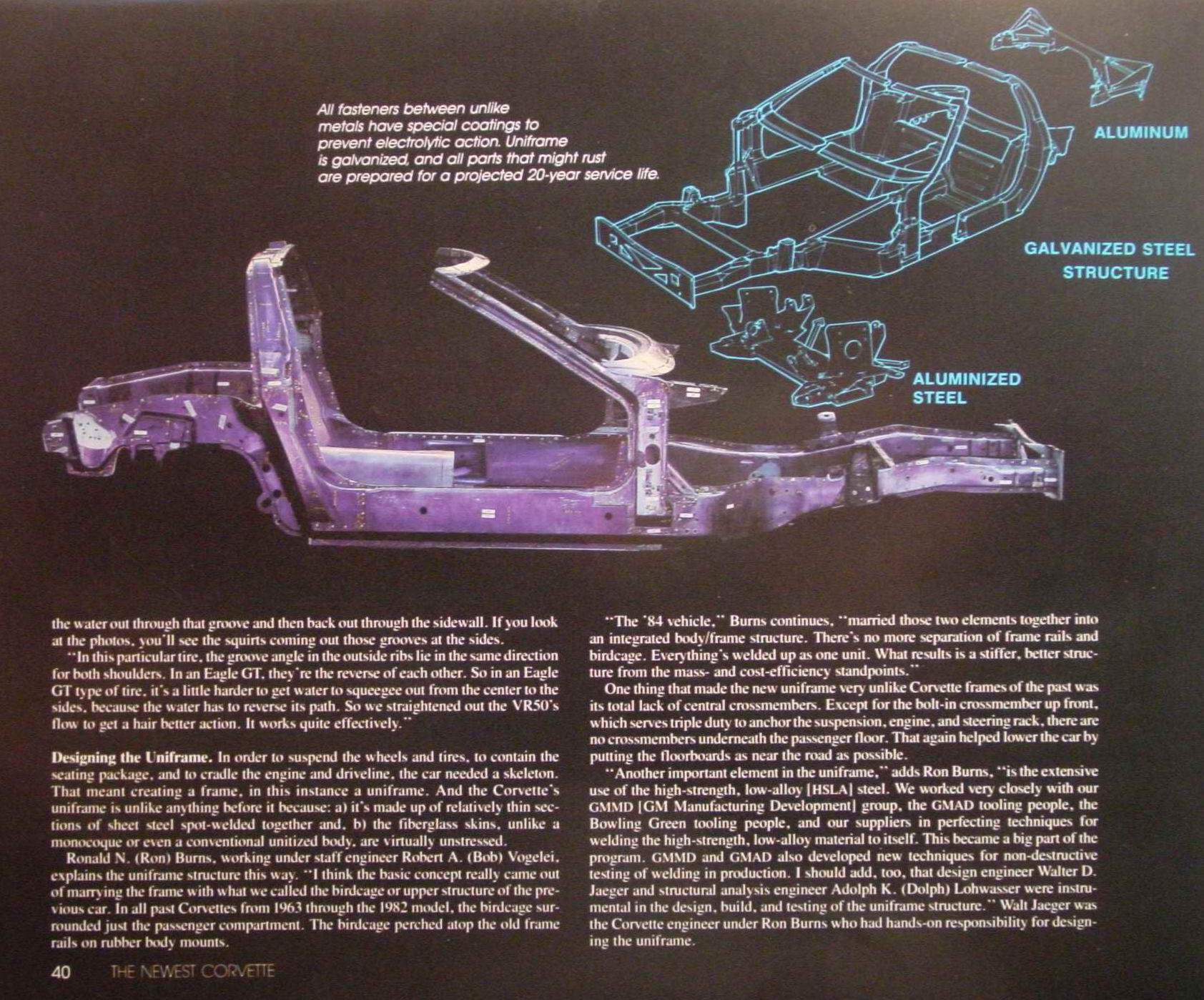
Recently it was stated on this forum, in reference to the over all strength or stiffness of the C4's frame, that "The "C" beam also helps with chassis integrity.", and that's not true. I've seen this same thing posted several times before, so wanted to post to clarify the roles and limitations of the C-beam.
The purpose of the C-beam is two fold; it holds up the azz end of the transmission, and it holds up (or down, depending on operating mode) the nose of the differential. That is ALL it does. What makes this piece unique, and advantageous over other designs in my opinion is that it accomplishes this with out heavy, stamped steel cross members. With out the aluminum C-beam, a heavy and strong steel member would be required to firmly hold the rear diff, which in a ZR-1 can exert up to ~3500 lb-ft of torque on the housing. So the C-beam reduces weight and space requirements to hold up the trans, and rotationally supports the differential housing -relative to the direction of desired wheel acceleration.
What it doesn't do: Add strength to the frame of the car, manage ANY type of torsional or side-bending loads, either for the drive train OR for the frame of the car.
As you can see in the pics below, the C-beam is only strong in one direction; bending on the vertical plane (there is some bending strength on the horizontal plane but not a lot)
In ^that^ pic, if you can imagine having huge hands, picking up the car by holding the front section and the rear assy, I think you can see that twisting it would be incredibly easy. What prevents twisting is this part of the car:
There is the frame and everything that provides the structure. The car (drive train) is a "wet noodle" until the above is lowered down onto the power train and bolted to it. THAT is when the power train achieves strength and stiffness, so to speak. An important note however is that the entire power train is mounted to the above pictured frame with rubber bushings -except for the K member which isn't really part of the power train, it's in the pic for marketing purposes. But the engine is mounted to the K member with rubber. Think of the engine, trans, C beam and rear diff as a single entity, "hung" in the above pictured frame with rubber. The C5^ is the same philosophy and design, only using a torque tube.
So what is the major down fall of this design as compared to the newer C5^? As I said earlier, the C beam isn't designed to, and can not manage torsional loads (torque). The engine/trans unit in a ZR-1 is capable of producing ~1300 lb-ft of torque (385ctqx2.68 1st gear ratio). There is the same amount of "resistant" torque imparted on the differential assy. What prevents the two "groups" from counter-rotating with one another? The frame of the car. The widely spread batwing mounts manage tq imparted on the diff, and the motor mounts manage torque generated by the engine/trans unit.
In the C5^, there is no meaningful torque exerted on the frame of the car. The Torque Tube does the same job as the C-bream, PLUS handles the tq loads between the front and rear segments...in this case tq is MUCH lower b/c the TT is only dealing with engine torque; a maximum=to max engine tq, since there is no gearing to multiply the tq. See pic and compare what you see here to the C beam pic above:
Again, think of the engine/clutch/TT/trans/diff as a single solid unit (that's what it IS), suspended in the frame from rubber bushings. The loads imparted on the frame of this design are mostly only radial in the lateral direction. In other words, the only major loads are those trying to lift the front of the car (through the motor mounts like in a C4) or push it down through the motor mounts (again, same as a C4) during acceleration and deceleration, respectively. Unlike a C4, the motor isn't trying to twist the front of the car in the opposite direction as the rear.
.
Last edited by Tom400CFI; Oct 9, 2022 at 12:28 PM.
Question, if the C beam doesn't provide any 'torquing' rigidity why is it reported that beam plates (zfdoc) help with the rear kicking to the side under hard shifts, etc?
I don't own beam plates so I can't vouch personally for their effectiveness.
So how do you feel about C Beam plates that are supposed to eliminate kick-out on the right side under load? I've installed them to ease installation of the C Beam but I'm not sure I buy into their other claims.
I broke my C beam when I took a right at a intersection in first gear with mild aggressive acceleration and at the same time hits some bumps. Now I'm nervous to get on it around a corner, scared its gonna snap again.
That is odd, but I'm guessing that the beam was going to break adn it is coincidence that it happened during a turn. In theory, the Beam shouldn't "know" or be able to tell when the car is cornering. Other than the "G force" applied to it by the "sway" of the rear of the trans.
Originally Posted by jmgtp
Question, if the C beam doesn't provide any 'torquing' rigidity why is it reported that beam plates (zfdoc) help with the rear kicking to the side under hard shifts, etc?
Originally Posted by cumbercr
So how do you feel about C Beam plates that are supposed to eliminate kick-out on the right side under load? I've installed them to ease installation of the C Beam but I'm not sure I buy into their other claims.
I don't buy into it either. My first thought is that it's the placebo effect like so many other parts that "help" (TB foil comes to mind). BUT, I haven't tried them either, and there could be other forces coming into play during a transient actions like a shift, that I'm not considering at the moment. This doesn't mean that I think the Beam plates don't have merit; I think they do...just not for that reason.
I think the beam plates are a good idea from the stand point of easier service of removing the c-beam. I've done lots of redline and not redline shifts I have yet to really notice the rear end getting squirmy on me.
I think the beam plates are a good idea from the stand point of easier service of removing the c-beam. I've done lots of redline and not redline shifts I have yet to really notice the rear end getting squirmy on me.
Same here. the car can/will lose traction...but mostly it just shoots forward. Not much kick-out in either direction unless there is a reason (cornering or crowned/sloped road surface).
Excellent post! I do agree that the beam plates only help when putting the beam back together. I dont have them since I just made holes above the bolts to put the nuts on easier. There is no rigidity improvement.
I made the statement & I'll stand my ground about it.
If no C beam & the trans had its own cross member + there were some type of upper control arms or pinion snubber for the differential to keep the pinion from running up the ring gear & disappearing into the floor pan the car would probably bend in the middle during a wheel stand launch especially if the targa was removed. Hence the C beam provides lateral stability/integrity.
If solid motor mounts are used & steel batwing bushings with heim joint dog bones etc. are in place in cars that are tracked the engine, trans, batwing, C beam are now a solid structural component. With rubber mounts the system is still a structural component but to a lesser degree dependent on the amount of bushing compliance.
I don't buy into it either. My first thought is that it's the placebo effect like so many other parts that "help" (TB foil comes to mind). BUT, I haven't tried them either, and there could be other forces coming into play during a transient actions like a shift, that I'm not considering at the moment. This doesn't mean that I think the Beam plates don't have merit; I think they do...just not for that reason.
Recently it was stated on this forum, in reference to the over all strength or stiffness of the C4's frame, that "The "C" beam also helps with chassis integrity.", and that's not true. I've seen this same thing posted several times before, so wanted to post to clarify the roles and limitations of the C-beam.
The purpose of the C-beam two fold; it holds up the azz end of the transmission, and it holds up (or down, depending on operating mode) the nose of the differential. That is ALL it does. What makes this piece unique, and advantageous over other designs in my opinion is that it accomplishes this with out heavy, stamped steel cross members. With out the aluminum C-beam, a heavy and strong steel member would be required to firmly hold the rear diff, which in a ZR-1 can exert up to 4500 lb-ft of torque on the housing. So the C-beam reduces weight and space requirements to hold up the trans, and rotationally supports the differential housing -relative to the direction of desired wheel acceleration.
What it doesn't do: Add strength to the frame of the car, manage ANY type of torsional loads, either for the drive train OR for the frame of the car.
As you can see in the pics below, the C-beam is only strong in one direction; bending on the vertical plane (there is some bending strength on the horizontal plane but not a lot)
If you can imagine having huge hands, picking up the car by holding the front section and the rear assy, I think you can see that twisting it would be incredibly easy. What prevents twisting is this part of the car:
There is the frame and everything that provides the structure. The car (drive train) is a "wet noodle" until the above is lowered down onto the power train and bolted to it. THAT is when the power train achieves strength and stiffness, so to speak. An important note however is that the entire power train is mounted to the above pictured frame with rubber bushings -except for the K member which isn't really part of the power train, it's in the pic for marketing purposes. But the engine is mounted to the K member with rubber. Think of the engine, trans, C beam and rear diff as a single entity, "hung" in the above pictured frame with rubber. The C5^ is the same philosophy and design, only using a torque tube.
So what is the major down fall of this design as compared to the newer C5^? As I said earlier, the C beam isn't designed to, and can not manage torsional loads (torque). The engine/trans unit in a ZR-1 is capable of producing ~1300 lb-ft of torque (385ctqx2.68 1st gear ratio). There is the same amount of "resistant" torque imparted on the differential assy. What prevents the two "groups" from counter-rotating with one another? The frame of the car. The widely spread batwing mounts manage tq imparted on the diff, and the motor mounts manage torque generated by the engine/trans unit.
In the C5^, there is no meaningful torque exerted on the frame of the car. The Torque Tube does the same job as the C-bream, PLUS handles the tq loads between the front and rear segments...in this case tq is MUCH lower b/c the TT is only dealing with engine torque; a maximum=to max engine tq, since there is no gearing to multiply the tq. See pic and compare what you see here to the C beam pic above:
Again, think of the engine/clutch/TT/trans/diff as a single solid unit (that's what it IS), suspended in the frame from rubber bushings. The loads imparted on the frame of this design are mostly only radial in the lateral direction. In other words, the only major loads are those trying to lift the front of the car (through the motor mounts like in a C4) or push it down through the motor mounts (again, same as a C4) during acceleration and deceleration, respectively. Unlike a C4, the motor isn't trying to twist the front of the car in the opposite direction as the rear.
If no C beam & the trans had its own cross member + there were some type of upper control arms or pinion snubber for the differential to keep the pinion from running up the ring gear & disappearing into the floor pan the car would probably bend in the middle during a wheel stand launch especially if the targa was removed. Hence the C beam provides lateral stability/integrity.
Your thinking is right, but there is way, WAY more strength in the rocker frame rails than the relatively flimsy C beam could ever provide, both for bending and especially for twisting. Evidence of this is solid rear axle converted cars that eliminate the C-beam; how many have bent in the middle? Just like the C4's frame does have to deal with drive train tq and the C5's doesn't, it's not an issue at all, because the strength comes from the frame of the car...not the c-beam. Yes, the C-beam lowers or moves some loads from the frame (to elsewhere in the frame), but the frame's integrity doesn't depend on, or need that. The C beam's function was to save weight and space. Think of all the parts required w/o the C-beam: You listed them above.
Originally Posted by Churchkey
If solid motor mounts are used & steel batwing bushings with heim joint dog bones etc. are in place in cars that are tracked the engine, trans, batwing, C beam are now a solid structural component. With rubber mounts the system is still a structural component but to a lesser degree dependent on the amount of bushing compliance.
In my first post, I was speaking of stock cars. Once we go down the road of "modding" too many things change for me to address, BUT let's talk solid mounts. It's true that solid mounts will improve the transfer of energy, it's still FAR from a "solid structural component" (at least in the C4). Why? B/c the C-beam has strength in only one direction (mostly). Even with solid mounts, virtually ALL the motor/trans tq is still going to be transferred into the frame of the car b/c the C-beam wasn't designed and can't accommodate those loads.
Day-dream about this; take a C4 rolling chassis (as in pics above). Weld up a "subframe" that ties the batwing to the trailing arms. Rig up a seat and controls and go drive the thing. Where is the "strength"? There is none. The thing will be a wet noddle and very likely will fold in half.
NOW, take a C4 frame, install a solid rear axle w/a tq arm mounted to a fabricated trans x-member, install a 1000hp engine and front suspension and wheels...go drive it. Where is the strength? It's there. Car would be 100% viable and plenty of people have already done this. The real strength is in the frame and the C beam is strong in one direction, designed to reduce space and weight.
Another thing to consider: in all the C4^ cars, if the powertrain assy were intended to be a structural member that enhances the over all strength of the frame, it would have to be solid mounted, and it's not. But if it were and that was the intent, there would be a plethora of other criteria...such as expansion; the majority of the drive train is aluminum (trans, C-beam, Diff) which as we all know, expands at a much greater rate than the steel frame. It also varies in temp MUCH more than the frame; from ambient, to ~200*F? The trans runs in the high 100's, C beam is heated by the exhaust, diff gets warmed by the exhaust and friction...the assy is going to "grow". One reason why the entire powertrain is "hung" buy rubber blobs in a stock car. If it's all solid mounted, where does that growth go? In a C4 it would like bend the C beam some...in a C5^, it would have to bend the mounting ears. Not good and not how "structures" are designed.
GM deliberately mounted the powertrain in the frame in the way that they did, because it's not designed to or attempting to add strength to the frame. The C-beam may remove loads from some areas of the frame (and introduces it elsewhere), but it doesn't attempt to ADD strength. The Frame is where all the meaningful strength is.
I'd like to apologize as I did not intend on "calling you out". But I do appreciate your weighing in on this thread. No matter what, it's all interesting to think/talk about, IMO, no matter our thoughts.
Last edited by Tom400CFI; Sep 2, 2012 at 01:28 PM.
What was stated is that the C beam adds to the integrity of the frame/chassis with no stipulation as to the degree of help. We all know that anything added such as an X brace from a vert or aftermarket links etc. also help to stiffen the poor original design.
From personal observations: Many of us here including myself will not drive a C4 with the targa removed, to much cowl shake which equates to insufficient chassis integrity.
In my friends new at the time early C4 vert the right door could not be opened & the left door had to be slammed to close it if he parked on uneven ground.
We have what GM gave us & work with it as each of us sees fit whether it involves installing a full cage, adding something to the chassis to help it, leaving the targa on or just enjoying the ride for what it is.
Designer Imagines A Corvette That Looks More Like a Corvette Than the Corvette
Slideshow: A Jaguar designer's personal project imagines what a modern front-engined Corvette might look like if Chevrolet revisited the golden age of the Stingray.